By: Miguel Gonzalez (Project Manager), Jeffery De La Cruz (MST), Jorge Hernandez (E&C)
Approved by: Miguel Garcia (Quality Assurance)
Mission Objective
By: Miguel Gonzalez (Project Manager & Manufacture)
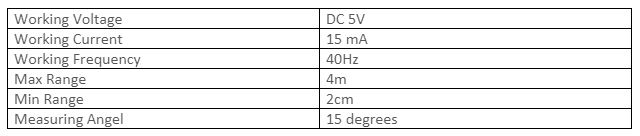
Our goal for this project is to design and manufacture a BiPed Robot. This robot will be slightly similar to the BiPed robot that was created in Spring 2016 and another bipedal robot named FOBO, created by Jonathan Dowdall. Our design will be based on FOBO but will be much smaller in size that implements micro servos for walking and turning. For sensing its surroundings, the robot will utilize ultrasonic and Infrared sensors. Other key differences between the FOBO and our micro version of FOBO are that:
- The head of our robot shall house a 3DoT board, servos controller shield, and a sensor shield.
- The movement of our robot will be conducted via SG90 micro servos that will replace the clunky and oversized Hitec HS-805BB servos.
- The legs of our robot will have a more efficient method to mount and utilize its servos for weight reduction and for longer walking steps.
- Our robot will utilize Bluetooth technology for user to robot communication and movement control
- The robot’s power system will be changed from heavy LIPO batteries to a single Samsung 18650 battery located near the robot’s center of mass.
The mission of Project BiPed is to design the BiPed to navigate a predesigned maze. The BiPed shall be able to navigate the maze with user input from the Arxterra App/Control Panel. The BiPed will be able to memorize the user-defined path and will be able to navigate it autonomously. In addition, the BiPed will acknowledge other robots while traversing the maze and avoid collisions using its sensors. To learn more about the mission objective you can take a look here. For preliminary maze designs and definitions take a look here.
Project: Level 1 Requirements
By: Jeffery De La Cruz (MST Engineer)
Verified By: Miguel Gonzalez (Project Manager)
Will:
L1-1: Micro FOBO will stand on its own without any physical help.
L1-2: Micro FOBO’s electronic components will be easily assembled and disassembled.
L1-3: Micro FOBO will have 2 legs.
L1-4: Micro FOBO will be a toy robot based on the design of the FOBO by Jonathan Dowdall.
L1-6: Micro FOBO will fit within the classroom cabinets shelves. 28”x13”x14.5”
L1-7: Micro FOBO will utilize a 3DoT board or Sparkfun Pro Micro 3.3V/8MHz.
L1-8: Micro FOBO’s part components will be 3D printed using the material carbon fiber PLA.
L1-9: Micro FOBO will not exceed a print time of 7.80 hours. Upon approval of the waiver.
Shall:
L1-10: Micro FOBO shall not exceed a cost of $250 to construct.
L1-11: Micro FOBO shall be 60% or less of the overall size of Jonathan Dowdall’s FOBO
L1-12: Micro FOBO shall detect intersections in the maze.
L1-13: Micro FOBO shall be able to perform static walking.
L1-14: Micro FOBO shall produce 90 degrees turn.
L1-15: Micro FOBO shall be guided through the maze with the use of the Arxterra application.
L1-16: Micro FOBO shall record the path of the maze.
L1-17: The Micro FOBO shall traverse the maze using the recorded path.
L1-18: Micro FOBO shall be able to traverse cloth, paper, and linoleum materials.
L1-19: The Final Biped shall be completed by May 10th, 2018.
Should:
L1-20: Micro FOBO should step over a square rod 1cm tall, 1 cm wide by 10 cm long
L1-21: Micro FOBO should be able to perform dynamic walking
System/Subsystem: Level 2 Requirements
By: Jeffery De La Cruz (MST Engineer)
Verified By: Miguel Gonzalez (Project Manager)
Will:
L2-1: Micro FOBO will be connected via Bluetooth to the app on an android phone.
L2-2: Micro FOBO dimensions of the robot will need to be small enough to fit in a 4in by 4in box for maze purposes.
L2-3: Micro FOBO will use SG90 micro servos.
Shall:
L2-4: Micro FOBO shall use UV/IR sensors to detect intersections.
L2-5: Micro FOBO shall use the color of the maze to establish if it needs to turn. black (0,0,0) green (0,255,0) for line following.
L2-6: Micro FOBO shall use a battery that outputs 3.7V nominal.
L2-7: The user shall use the Arxterra application to move the robot forward, backward, left, and right.
L2-8: Micro FOBO connectors shall be able to connect and reconnect all the wiring in less than 10 min.
L2-9: Micro FOBO wiring shall be nice and clean with the use of terminal blocks, contact pins, 2.0mm PH series JST connectors, and barrel connectors.
L2-10: Micro FOBO shall play a musical tune when the maze is completed.
L2-11: Micro FOBO shall have indicating LEDs to demonstrate either a left or right turn.
L2-12: The Micro FOBO shall record the path of the robot on the 3DoT board or the Sparkfun Pro Micro 3.3V/8MHz to navigate the robot through the maze.
L2-13: Micro FOBO shall use a 3D printed chassis and leg components.
L2-14: Micro FOBO shall measure within 4.5” x 3.25” x 7.25”.
L2-15: Micro FOBO shall weigh no more than the allocated mass of 460g.
L2-16: Micro FOBO shall detect objects 8 inches from it.
Should:
L2-17: Micro FOBO should be able to see other robots to avoid a collision. The robot will stop completely and wait for clearance. (Ultrasonic sensor)
L2-18: Micro FOBO should take a bow at the end of the maze as a victory celebration.
System Block Diagram
By: Jorge Hernandez (E&C Engineer)
Verified By: Miguel Gonzalez (Project Manager)
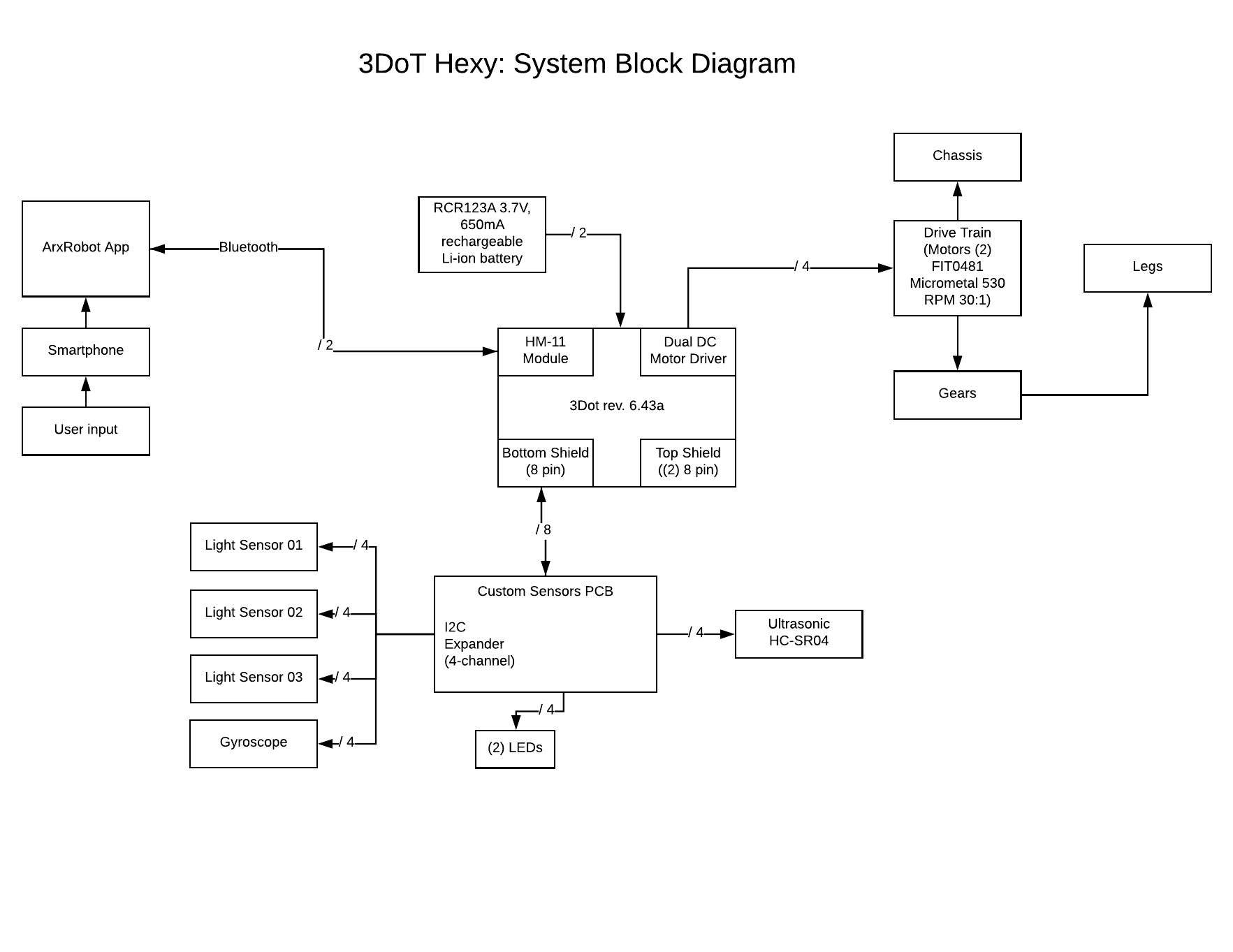
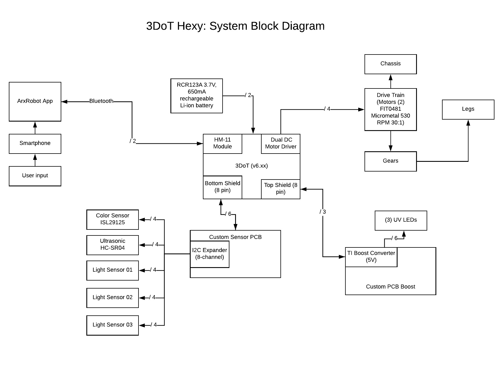
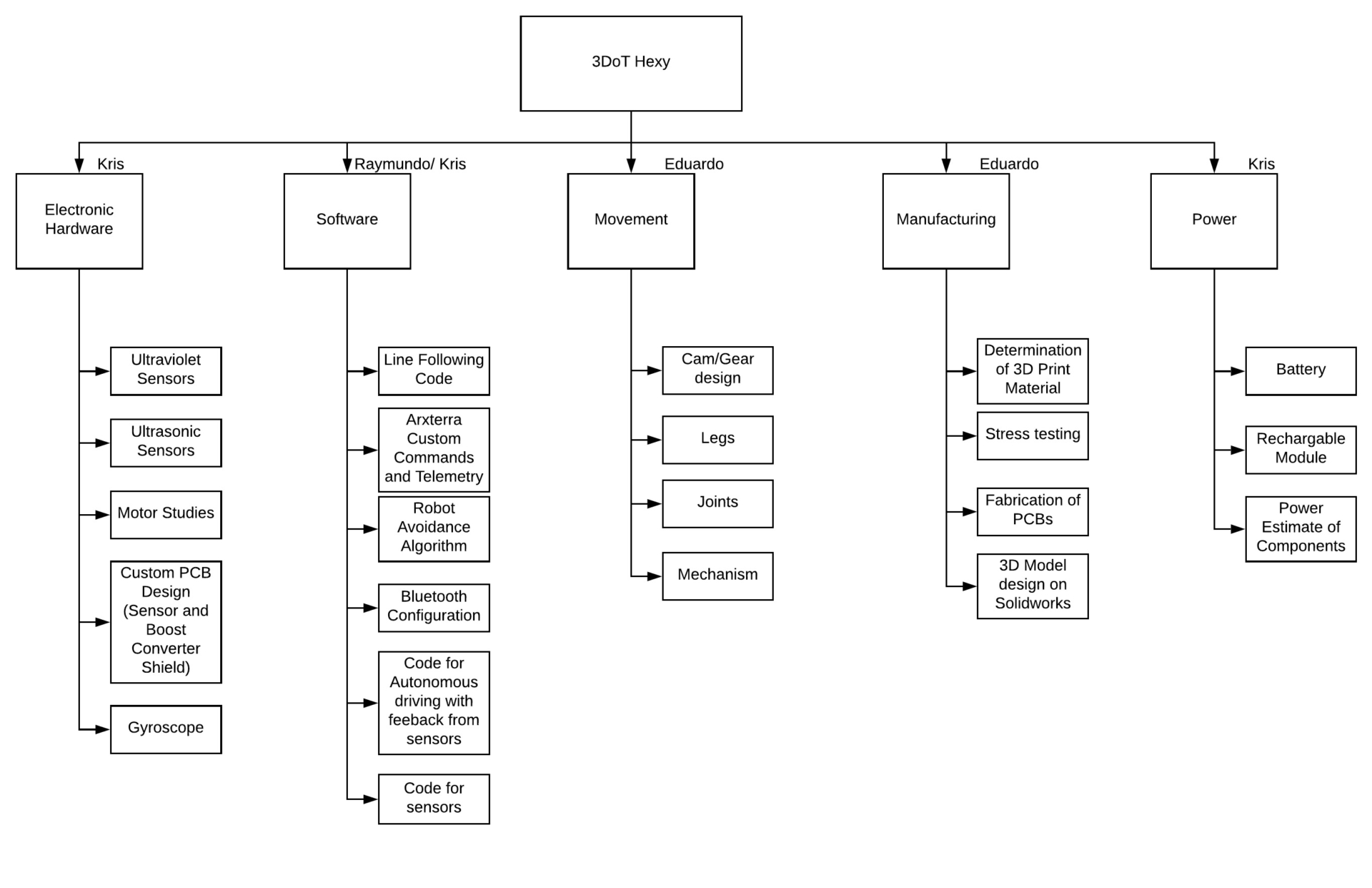
After looking at all the constraints and requirements for the robot our group came up with a system block diagram that could help us visualize how the robot’s components interacted with one another. This diagram made it clear to understand where initial designs should be made and provided great insists to some challenges we would have in the future. For example, we can see the product breakdown structure down below and notice that our robot’s chassis contains more sub-branches than the rest of the diagram sibling branches. This indicates that most of the designing will be involved in the creation of the robot’s main hardware. This would help our manufacturing engineer know that designing of the robot’s chassis should be done as early as possible to prevent set back. Another branch that stands out is the software section. This branch is made up of multiple sections that include Arxterra control, line following, avoidance detection, and turning code. This branch is important as the diagram illustrates that our robot is highly dependent on its software to achieve a successful mission objective.
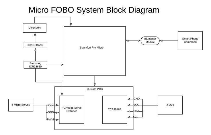
Fig.1 System Block Diagram
Work Breakdown Structure
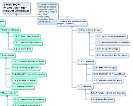
By: Miguel Gonzalez (Project Manager & Manufacture)
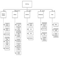
Once we had a clear idea of how the robot would be made we proceed to create a WBS. A work breakdown structure allows us to list and assign tasks/work that needs to be completed for the success of the robot. The tasked listed on the WBS based on the team member’s job description and are directly imported from the tasks created on the Spring 2018 Task Matrix that can be found here. The diagram below is a much easier method of reading the tasked matrix as it clearly shows each team member’s responsibilities.
Our group consists of three members fulfilling the roles of Project Manager, E&C, MST, and Manufacturing Engineer. Since the group has fewer members than the positions available the manufacturing role of the team was given to the Project Manager.
The diagram below shows the workload of the project and how it is distributed among the team. It is based on the job descriptions and shows major tasks that each person is responsible for. We will be taking a look at each team members role more closely to better understand the structure of the team and its workload.
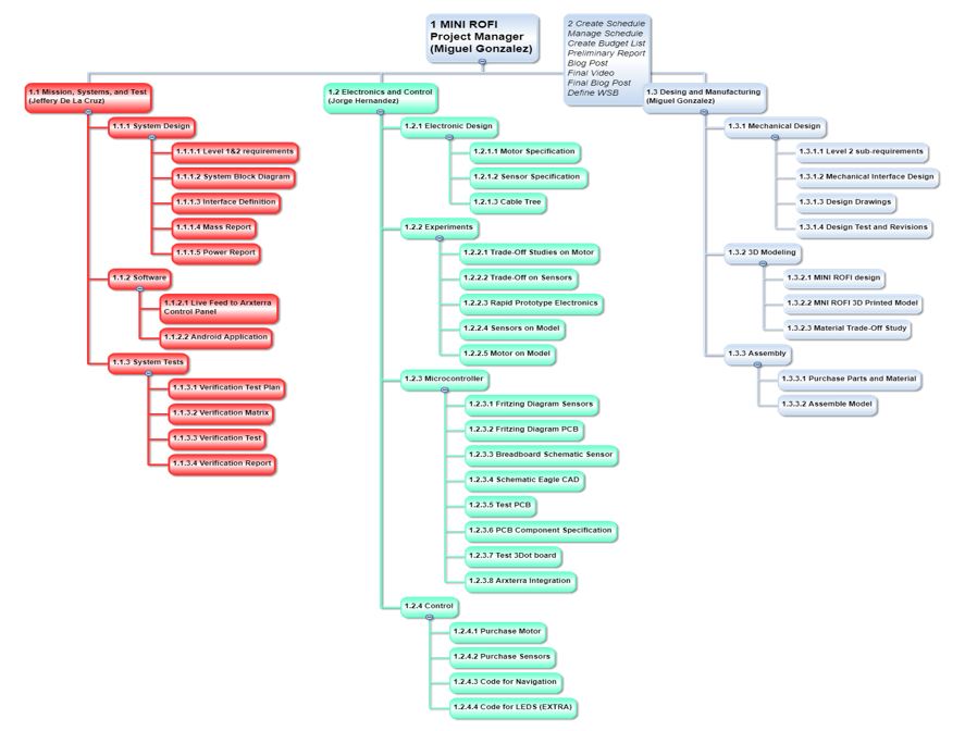
Fig.2 BiPed Work Breakdown Structure
Miguel Gonzalez (Project Manager)
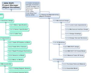
Fig.3 PM and Manufacturing Engineer Tasks (Blue)
At the top of the WBS in blue, we have the project manager section. Note that in our case the project manager is also the manufacturing engineer and thus the tasks for both roles are given to the same person. The second blue icon shows the tasks specific to the project manager which has the project manager responsible for the following tasks:
- Creating and managing schedule
- Creating a budget list
- Creating the preliminary report
- Creating the final blog post
- Creating project video
- Define Work Breakdown Schedule
The manufacturing tasks given to the project manager are listed to the right side of the WBS also in blue. These tasks are broken down into three sections Mechanical Design, 3D Modeling, and Assembly. These sections were created based on which tasks are needed to be done before moving on to the next section. For example, Mechanical Design is a prerequisite for 3D Modeling and Assemble thus it is located on top of the other tasks.
Jeffery De La Cruz (MST)
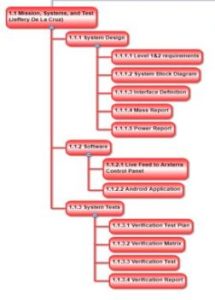
Fig.4 MST Tasks (Red)
Moving on to the left side of the WBS (in red), we have all the tasks assigned to the MST engineer. Once again, these tasks are divided up into three sections System Designs, Software, and System Tests. The system designs include tasks that have a focus on research and trade studies that will end up helping with the software development and system test. Once those tasks are done the MST engineer can proceed with implementing the software with the Arxterra control panel and onto an android application. The final tasks for the MST engineer focus on verifying and testing all sections of the robot to see if they are operational.
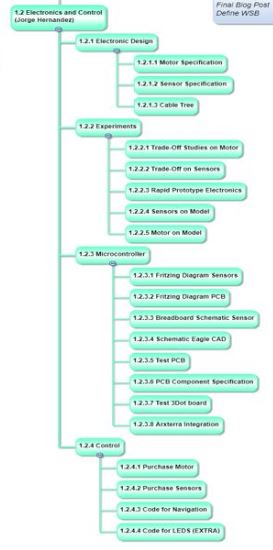
Jorge Hernandez (E&C)
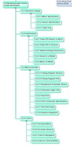
Fig.5 E&C Tasks (Green)
The final branch in the WBS applies to the E&C engineer and his tasks needed for a successful project. The E&C has the greatest responsibility for the success of the robot becoming operational. His roles are divided into 4 categories Electronics Design, Experiments, Microcontroller, and Control. These categories cover a wide range of tasks that need to be realized to proceed with the overall goal of the Biped project.
Product Breakdown Structure
By: Jeffery De La Cruz (MST Engineer)
Verified By: Miguel Gonzalez (Project Manager)
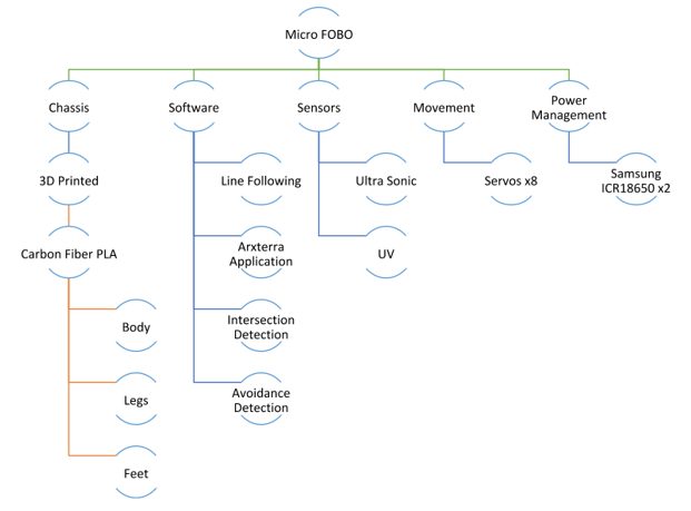
Fig.6 Product Breakdown Structure
Based on System Block
Sensor Suite
- The color sensor will be able to detect colors and its data input range Ex, black (0,0,0) green (0,255,0) for line following.
- Will be able to see intersection sign on the maze and differentiate its color from the path lines.
- Shall be able to see other robots to avoid a collision. The robot will stop completely and wait for a command. (Ultrasonic sensor/IR)
- The robot should have to indicate LEDs to show where the robot plans to make a turn (left or right)
Smartphone App
- Will allow usage of the app to navigate the robot through the maze through forward, back, left, and right commands.
- Will record the path of the robot in 3Dot board to navigate robot without the user controlling it.
- The robot will be connected via Bluetooth to the app on an android phone.
Chassis
- The wiring for the robot shall be nice and clean with the use of terminal blocks, contact pins, 2.0mm PH series JST connectors, and barrel connectors.
- All connectors shall be able to connect and reconnect all the wiring in less than 5 min.
- Dimensions of the robot will need to be small enough to fit in a 6in by 6in box for maze purposes.
Battery
- The robot power management system will use two 1000mAh 2S 20C Lipo Pack rechargeable LIPO batteries.
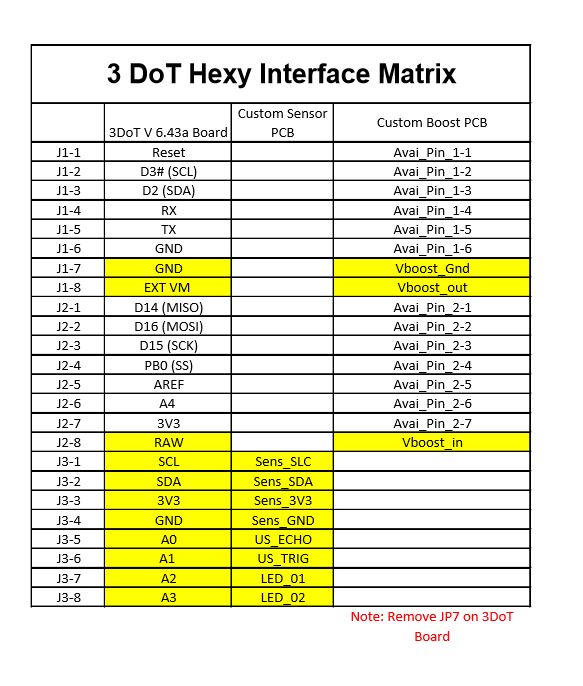
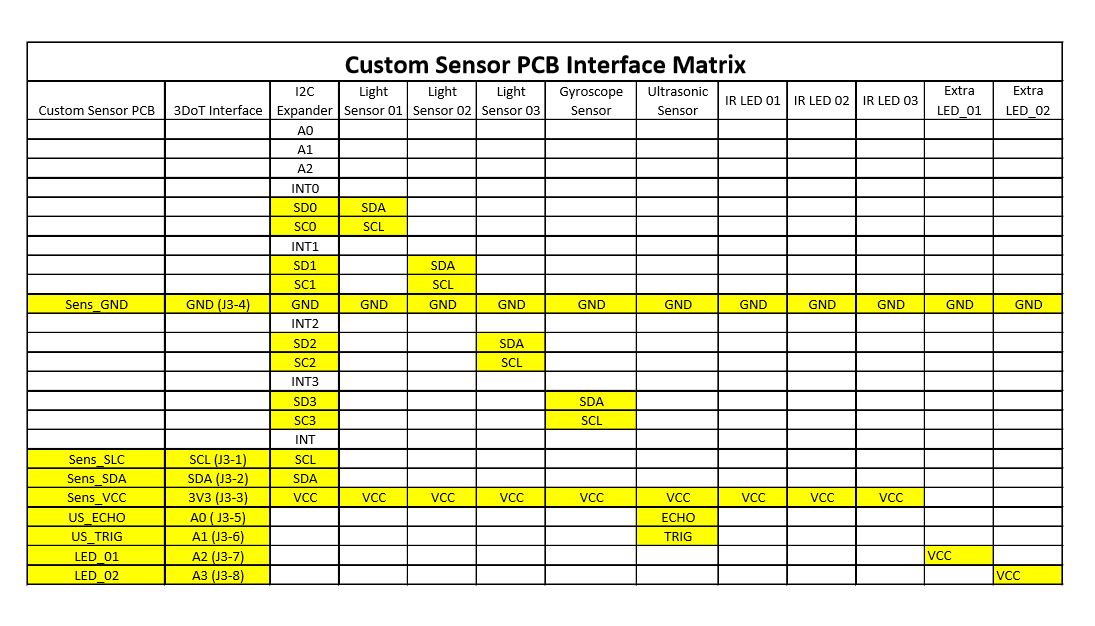
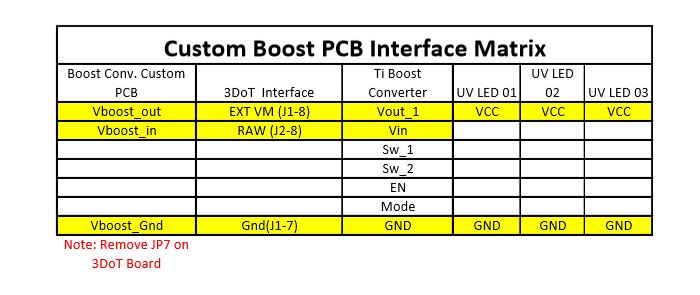
Interface Matrix
By: Jeffery De La Cruz (MST Engineer)
Verified By: Miguel Gonzalez (Project Manager)
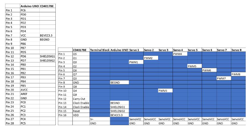
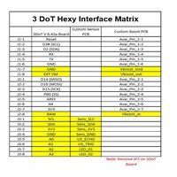
Fig.7 Interface Matrix
The current interface matrix for the prototype Micro FOBO uses the Arduino UNO. A CD4017BE IC was used to control the eight servos. The output of the CD4017BE IC has then connected the Arduino UNO which will the Robot Poser control the movement of the servos so that the Micro FOBO can walk. The interface matrix will be updated once the 3DoT board or the Sparkfun Pro Micro 3.3V/MHz is acquired. This is currently for the prototype of the Micro FOBO. The excel file containing the interface matrix for the prototype Micro FOBO can be found here.
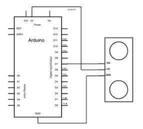
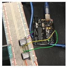
Prototype Fritzing Diagram for Biped
By: Jorge Hernandez (E&C Engineer)
Verified By: Miguel Gonzalez (Project Manager)
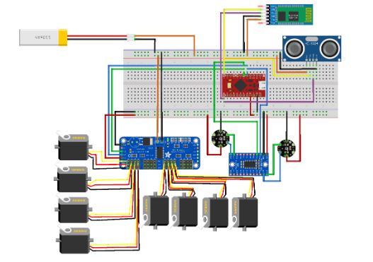
The Fritzing application allows a physical breadboard design to be created digitally. By designing a digital version, the beginning PCB designs can begin. One difficulty with using the free software is that the library does not have all the parts needed for many designs. Using Google, many of the parts required were found with Github.
Here are links to the Fritzing libraries for FOBO:
(If using the Adafruit Servo Driver)
https://github.com/adafruit/Fritzing-Library
(For the Bluetooth Module HC-06 and Accelerometer/Gyroscope MPU-6050)
https://github.com/RafaGS/Fritzing
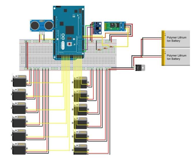
Fig.8 Electronic Fritzing Diagram
There was nothing to change at all as we are using the FOBO’s same hardware build. We decided
to go with 2 Lithium Ion batteries, 12 servos, and ultrasonic as well. The color sensor is being
discussed since we know Spiderbot wants to use UV sensors but will be added to fritz diagram
once we know the final maze descriptions.
References
Spring 2016 ROFI
Spring 2017 Velociraptor
Updated Fritzing
Mechanical Drawings
By: Miguel Gonzalez (Project Manager & Manufacture)
Related Requirements
Level One Requirements
L1-3: Micro FOBO will have 2 legs.
L1-4: Micro FOBO will be a toy robot based on the design of the FOBO by Jonathan Dowdall.
L1-11: Micro FOBO shall be 60% or less of the overall size of Jonathan Dowdall’s FOBO
Level Two Requirements
L2-2: Micro FOBO dimensions will need to be small enough to fit in a 4in by 4in box for maze purposes.
L2-14: Micro FOBO shall measure within 4.5” x 3.25” x 7.25”.
Micro FOBO Design
For some clarification and for better understanding our design of the Micro FOBO, I have created a color-coded assembly of the robot with matching titles indicating the names of each component. Below I discuss the design of these components that make up the Micro FOBO.
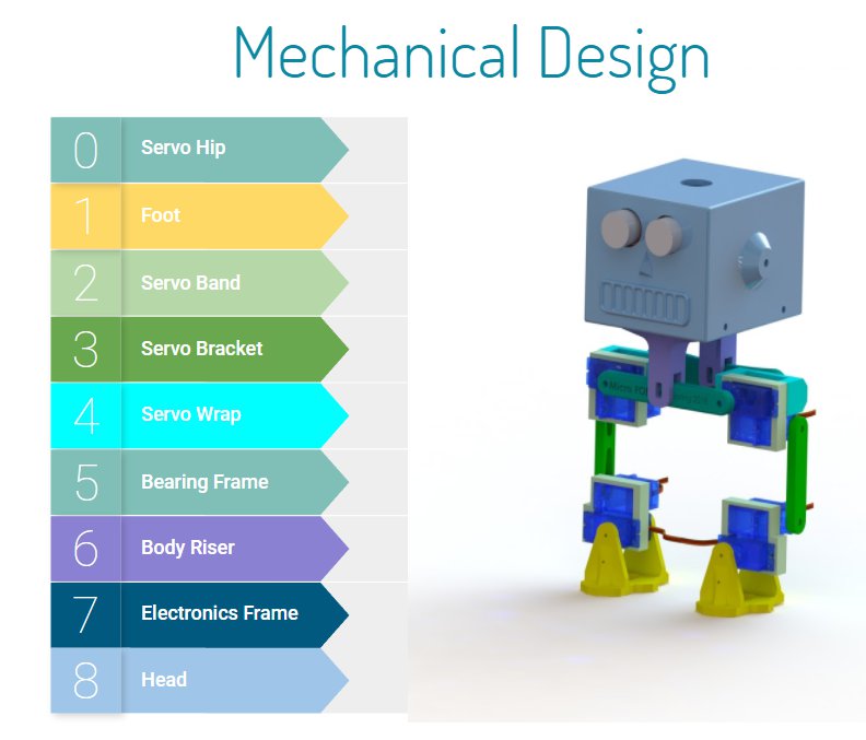
Fig.9 Micro FOBO Colored Parts
As you can see from the image above, the Micro FOBO consist of 9 different parts: Servo Hip, Foot, Servo Band, Servo Bracket, Servo Wrap, Bearing Frame, Body Riser, Electronics Frame, and the Head. Note that Micro FOBO can be made up of multiple copies of the same part component and thus colored coded with the same color. For example, there are four servo bands in Micro FOBO which are shown in light green on the picture. Now that we know which parts make up the robot we can begin looking at the design of each part individually.
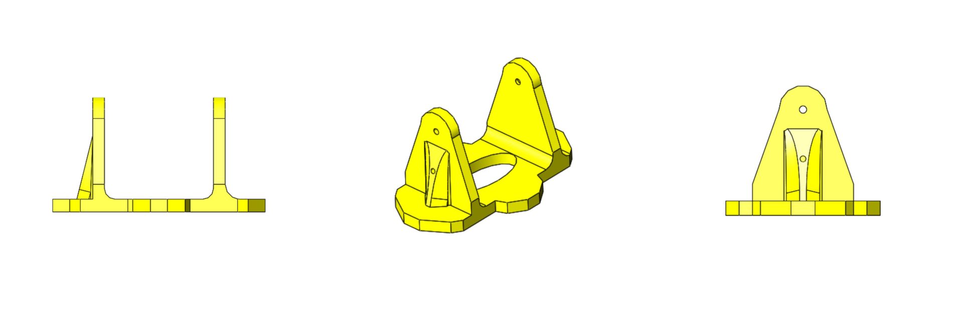
Part 0: Servo Hip
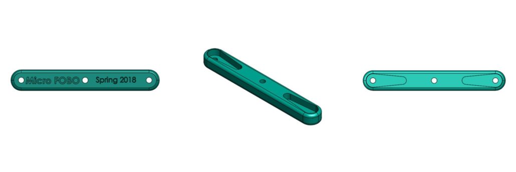
Fig.10 Part 0: Servo Hip
The “Servo Hip” component of the Micro FOBO is responsible for attaching the two upper micro servos which are the hip servos. This bracket connects both servos (right and left legs) together to act as a hip bone that allows the robot to move its legs left to right. The connection to the servos is made via servo horns that are provided by the manufacturer. This part has two allocated trenches that match the dimensions of the servo horns allowing the servos to mount to the part. The horns are then screwed onto the servo hip using M2.5 screws that are 8mm in length.
Drawing File

Fig.11 Part 1: Foot
The “Foot” component is the same for both legs and is a simple shoe like design with wide pads on its sides. The extra material on the sides allows a greater amount of surface to touch the floor allowing the robot to balance easier. Currently, this part is in its simplified state as there is not much detail design put on it. This is because the team plans on mounting UV sensors onto the bottom of the foot where the hole is located. This would allow the sensor to be as close to the ground as possible to maintain an accurate reading. Once we receive the sensor additional design changes will be made to this part. Currently, the part allows the ankle servo, which is the servo closest to the ground, to be mounted onto one side of the foot though servo horn cutouts. The horn cutout is located on the inside wall of the part. The hole then allows an M2.5 X8 screw to secure the servo onto the foot piece.
Drawing File
Part 2: Servo Band

Fig. 12 Part 2: Servo Band
There is a total of four “Servo Bands” located on the Micro FOBO. This part is responsible for grouping two micro servos together which forms a section of a leg. The two servos are pressure fitted into the square cutout and thus this part must be dimensionally precise to prevent servos to come loose. This piece had several revisions to satisfy the dimensional accuracy need to keep the servos secure. The servos were measured with a caliper and the thickness of the servos stickers even had to be considered when designing this piece. Due to leg movement constraints, only one servo can have extra material to be screwed onto the part.
Drawing File
Part 3: Servo Bracket
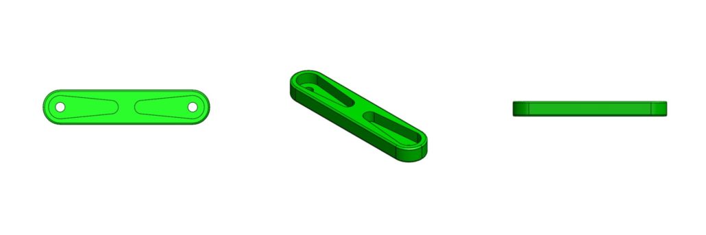
Fig.13 Part 3: Servo Bracket
The ‘Servo Bracket” is a shorter version of part 0: servo hip and serves a similar purpose. This component mounts onto two servos that are located on the servo bands. This allows the second to the top servo to move the lower leg. This piece is located in the middle of the leg and connects the top and lower sections. This piece can be thought as the knee of the robot. Just like the other brackets, there are two cutout trenches that allow servo horns to be mounted and secured through a single screw. This piece can be varied in length to adjust the height of the robot and adjust the walking stride of the robot itself.
Drawing File
Part 4: Servo Wrap
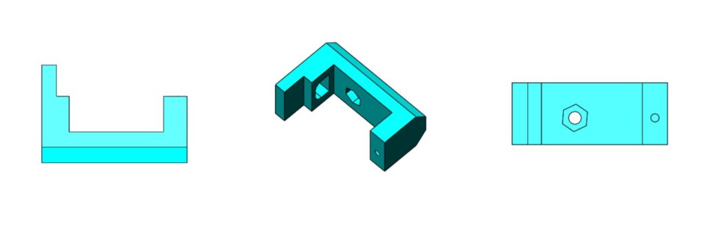
Fig.14 Part 4: Servo Wrap
The “Servo Wrap” is a small piece that attaches the back of the hip servo (top leg servo) to be mounted onto part 5: Bearing Frame. It is connected via an M2 screw that is 18mm in length. The screw goes through the servo, through the servo band, and screws into this piece. A hole on the left side of the wall was added to allow the servo wires to feed through and connect back to the electronics. Notice there is a hexagon trench located near the middle of the part. This trench allows an M3 nut to be placed in that location and lets a screw to secure Part 4 with Part 5. Another key design feature is the chamfer cutout located on the backside of the part. This permits higher degrees of movement from the hip servos by at least 45 degrees more.
Drawing File
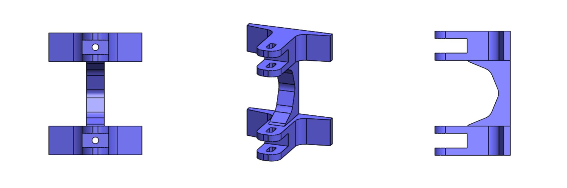
Part 5: Bearing Frame
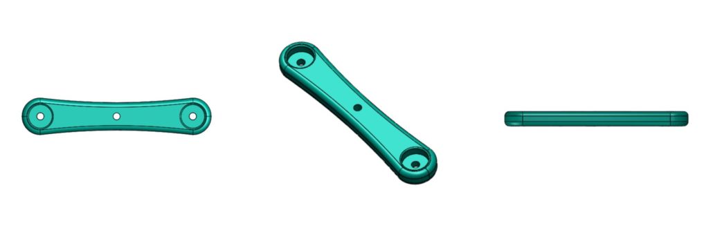
Fig.15 Part 5: Bearing Frame
The “Bearing Frame” is a mirror-like component to part 0 as both pieces work together to provide the connection of legs to body. One of the key differences is that this piece contains two large circular trenches in which a bearing can fit onto. Using a 10mm circular bearing we place it on the part to provide free angular movement to the left and right sides of the pieces. Once the bearings are fitted inside, we can use M3X14 bolts to attach the servo wrap pieces to the left and right side of the Bearing Frame. Since the legs servos are already attached to the servo wrap we effectively attached the two legs to the body of the robot.
Drawing File
Part 6: Body Riser
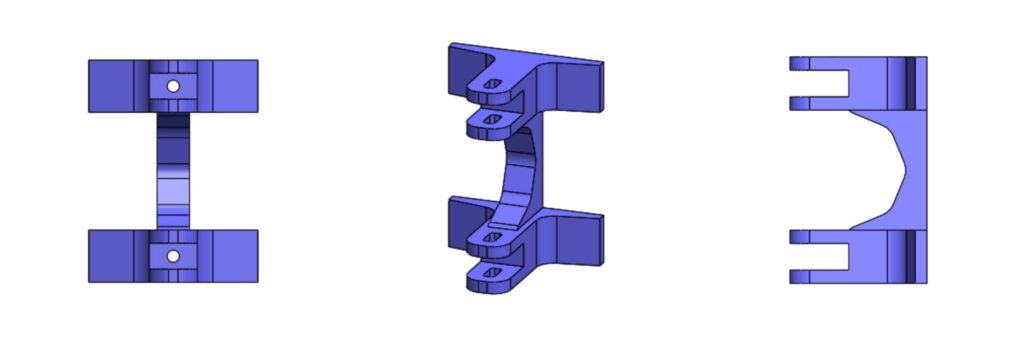
Fig.16 Part 6: Body Riser
Micro FOBO mainly consists of a head and two legs but this part, body riser, can be considered the body of the robot. This component connects the two attached legs with the head. There are two fork-like structures located at the top of the piece that allows part 0 and part 5 to fit in snugly effectively connecting the two legs to this piece. Part 0 and part 6 are secured through a couple of M3 screws with an approximate length of 16 mm. The back side of this component is flat and has two holes for connecting to part 7 which is the electronics frame. The body riser can be increased in height allowing the robot’s head to be located higher above the legs. We can experiment with changing the height to allow shifting the robot’s center of mass higher or lower as needed.
Drawing File
Part 7: Electronics Frame

Fig.17 Part 7: Electronics Frame
The Electronics Frame is a thin component that is responsible for connecting the PCB to the body riser. The PCB will contain four mounting holes which will allow the board to connect to this part. Note that the part contains extruded cubes that correspond to the location of the PCB hole mounts. These extruded cubes also have a hole cut out to fit M3 screws that secure the board in place. Finally, the part can be secured to the head via similar M3 screws on the side of the part and head
Drawing File
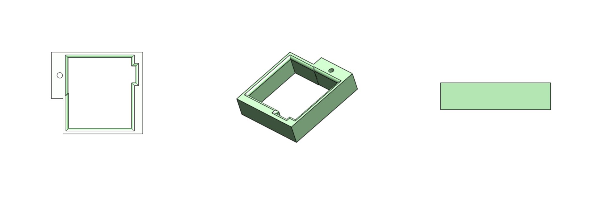
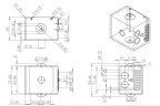
Part 8: Head
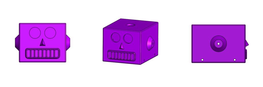
Fig.18 Part 8: Head
One of the first challenges in creating a miniature FOBO we observed was that our robot would need to support large amounts of electronic components that used to be on the regular size FOBO. These electronics would need to be smaller in size or our head design would need to optimize to fit all the electronics. Our first design was based on the prediction that the new electronics would have a smaller footprint and thus the head of the Micro FOBO is much smaller. The exact dimensions can be found on the link below. Once the size of the head was set I began to look at some redesigns that I can implement to change the look and functionality of the robot’s head. That is when I stumbled on an image of a tin toy robot from the 1950s.
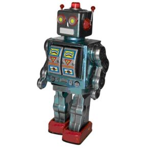
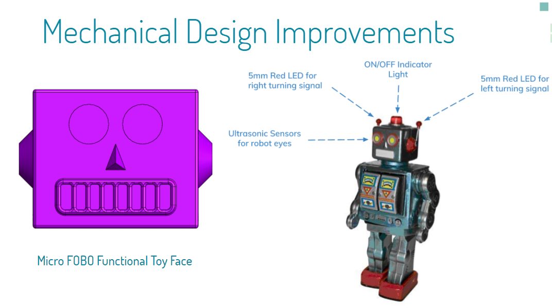
Fig.19 1950’s Tin Toy
As you can see from the image above this robot has a similar head as the FOBO which gave me the idea of emulating the design of the face. The ultrasonic sensor will take place as the robot’s eyes and the mouth and nose features would simply be aesthetics. Another thing that I noticed was that the tin toy contained antennas on the left and right side of the head. One of the redesigns I wanted to incorporate since the beginning was adding turn signals to the robot and the antennas can certainly be used for that. My idea is to have small 5mm red LED’s as the tip of the antennas that would blink indicating when the robot will turn and in what direction. Finally, we see that there is a small red light on top of the robot that can be designed to indicate on/off status of the robot.
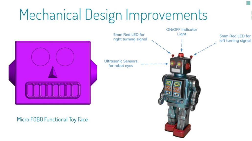
Fig.20 Mechanical Design Improvements
Drawing File Tin Robot Toy
Resource Reports (Power, Mass, Cost)
By: Jeffery De La Cruz (MST Engineer)
Verified By: Miguel Gonzalez (Project Manager)
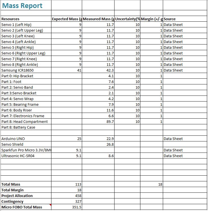
Below are the preliminary resource reports for the mass, power, and cost for Project BiPed. As we continue working on Project BiPed, the resource report will be updated to the actual numbers of each mass, power, and cost.
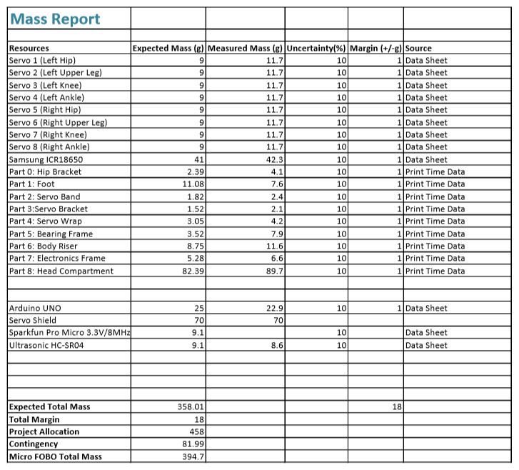
Fig. 21 Mass Report
The total mass of the Micro FOBO is at around 351.5 grams. This mass consists of the following:
Part 0: Hip Bracket x1
Part 1: Foot x2
Part 2: Servo Band x4
Part 3: Servo Bracket x2
Part 4: Servo Wrap x2
Part 5: Bearing Frame x1
Part 6: Body Riser x1
Part 7: Electronics Frame x1
Part 8: Head Compartment x1
Micro Servos x8
Samsung ICR18650 x1
Arduino UNO x1
Servo Shield x1
Ultrasonic HC-SR04 x1
To view the excel file of the mass report, click here.
The mass of the Micro FOBO will change because the material used to print the parts of the Micro FOBO will change from regular PLA to carbon fiber PLA. The Micro FOBO will become just lighter but not by much. The mass of the Arduino UNO and servo shield is included at the moment but will be updated once the 3DoT Board of the Sparkfun Pro Micro 3.3V/8MHz is included. Also, the battery case was not included because the position of the battery is to be determined.
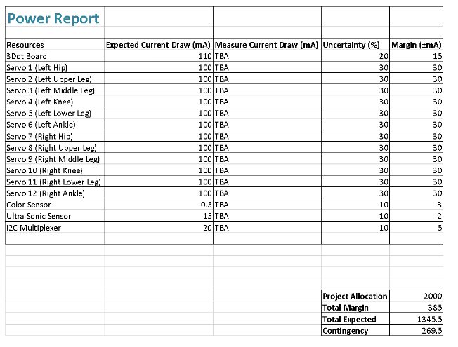
Fig.22 Power Report
Cost Report
By: Miguel Gonzalez (Project Manager & Manufacture)
Related Requirement
L1-10: Micro FOBO shall not exceed a cost of $250 to construct.
Project BiPed is one of this semesters robot production division in which a bipedal robot will be designed, engineered, and produced by the end of the semester. One of the most important tasks of any project is to evaluate and determine the cost of production of said products. In this post, we will be looking at the estimated cost of producing the BiPed robot. These costs will solely rely on physical component cost and any design and research development cost will not be mentioned in this post.
As part of the requirements stated by the customer, a budget was set for each project divisions. This is a loosely budget of $250 in which all material bought can be reimbursed in full. Any additional items and/or services that exceeded this budget will be covered by the team members working on the project. To help reduce costs, the customer has allowed access to his lab stock inventory of electronics, hardware, and materials. Borrowed items will be included in the budget table but the costs of the items will not be included in the total money spent.
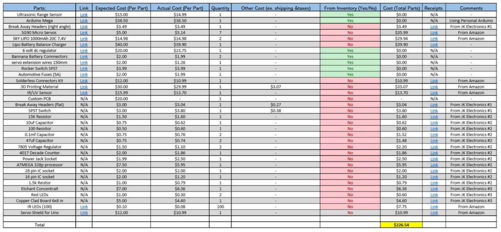
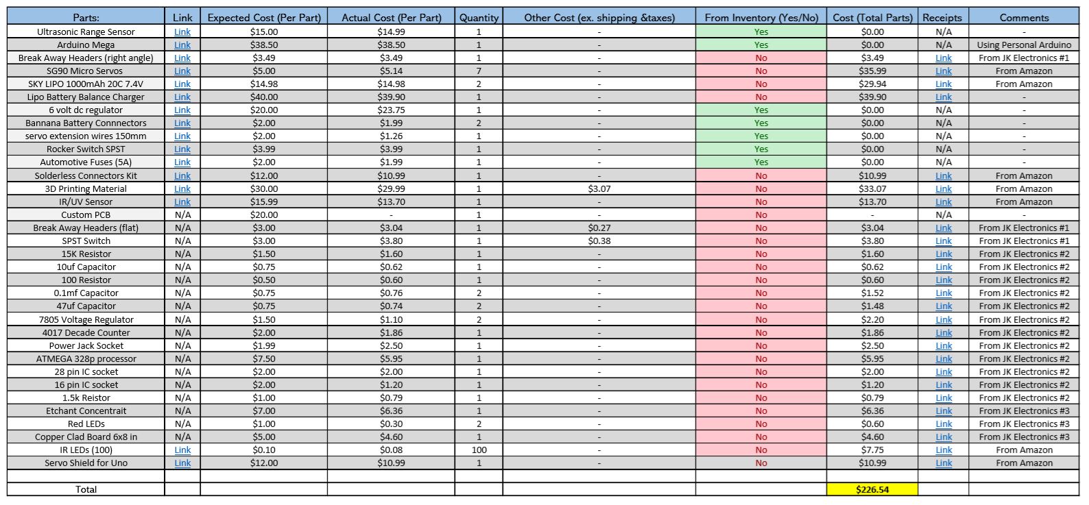
Fig.23 Spring 2018 BiPed Budget Table
Budget Table (for access to links found on the table)
The above table shows the cost of components we have used and purchased as of April 18, 2018. The budget table above is divided into ten separate columns indicating important information about the used and purchased products. In the left column are the names of the parts and items used by the team to produce the biped robot. To the right of the parts column, is a link section that allows viewers to find the same parts we used for this project online. The table is also set up for invoice collection for any items that were purchased these invoices/receipts are linked on the second column to the right of the table. The budget table tries to incorporate all useful information that may be needed for future part purchases, replacement of parts, and for reimbursements.
Overall, we wanted to make sure not to spend any unnecessary money and to reuse as many electrical components and hardware as we could. It is important to note that some additions to the table will be made as the project continues and more items are needed. Multiple hours of reading past blogs as well as research were done to reduce unnecessary consumption of resources and to allocate as much possible reused parts from previous semester projects. Our total expenditures as of April 18, 2018, is a grand total of $226.54 which is under the customer’s project funding of $250.
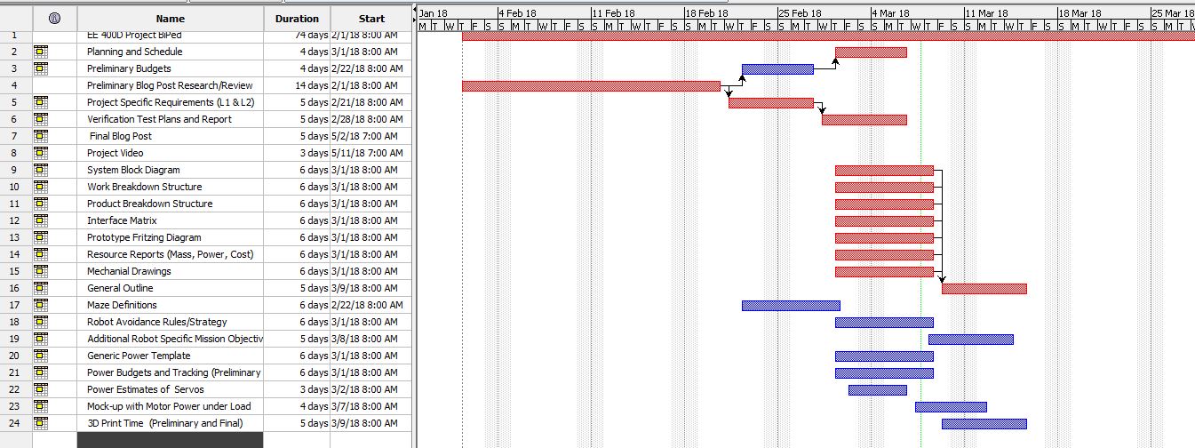
Planning & Schedule
By: Miguel Gonzalez (Project Manager & Manufacture)
This schedule is comprehensive and accounts for all tasks that should be completed by the displayed due dates. Using Project Libre, we can list the tasks needed to have a successful project. By using the Gantt chart feature we can see the tasks in a much more comprehensive chart that clearly demonstrates time frames and work periods. All tasks and due dates listed were imported from our class task matrix.
Overall Goal
Of course, like any project, our goal for BiPed robot is to finish every task on time while meeting our initial level one and level two requirements. To succeed, the following Gantt Chart was created with very precise timelines and due dates for procedural tasks that must be met to succeed in completing the BiPed robot on time. When creating the Gantt Chart, we notice three major tasks that are important to the success of the project. These tasks were the general project plan, finalization of the 3D model, and the final blog post. The deadlines for these tasks are March 15th, April 12, and May 8th in that order. Because the completion of these tasks is important we made sure to leave time after deadlines for adjustment and revisions. It is allowable to miss a deadline for tasks, but a penalty exists that increases as time passes. To prevent loss of points, additional precautions were put in place. As a group, we set the goal to complete these important tasks and blogs one class day in advance to confirm the completion of tasks within the timeframe.
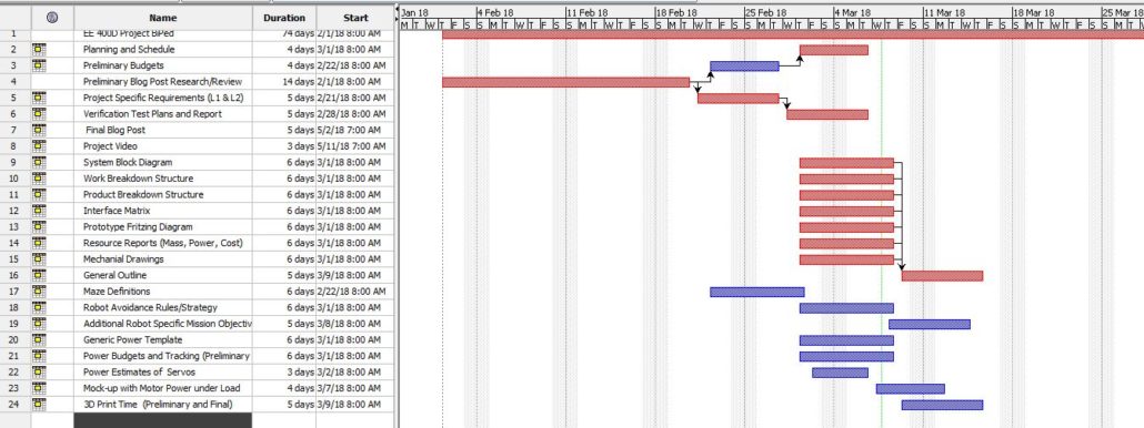
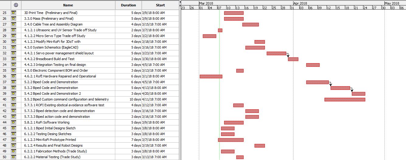
Fig.24 Gantt Chart pt1
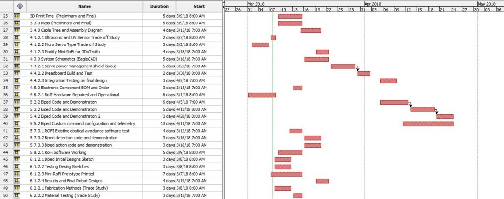
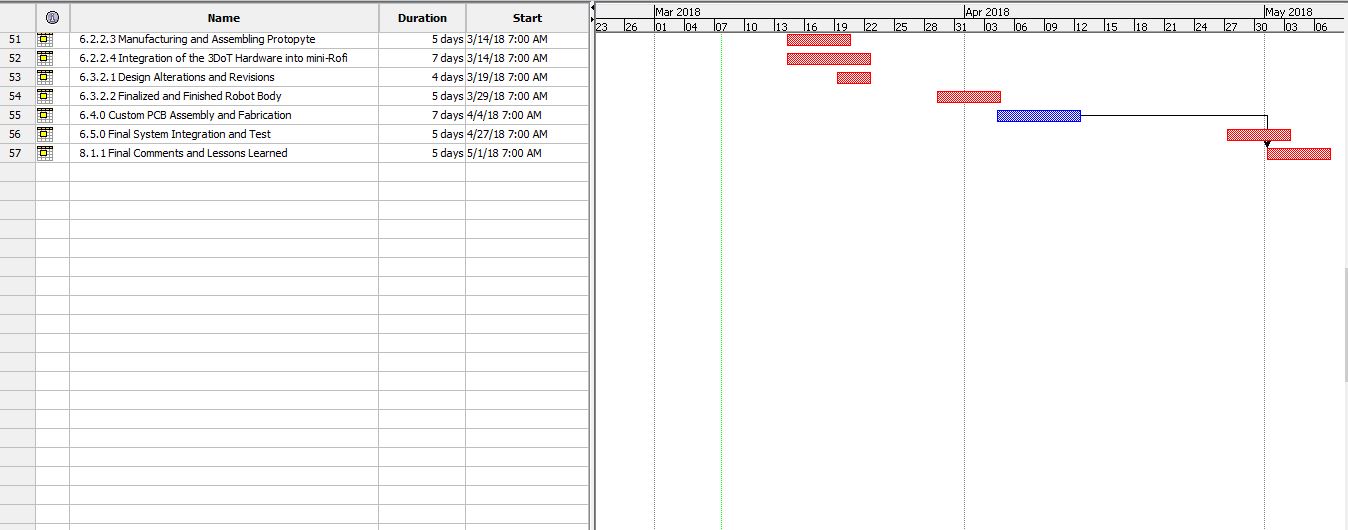
Fig.25 Gantt Chart pt2
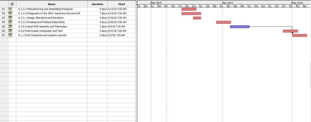
Fig.26 Gantt Chart pt.3
Burndown Chart
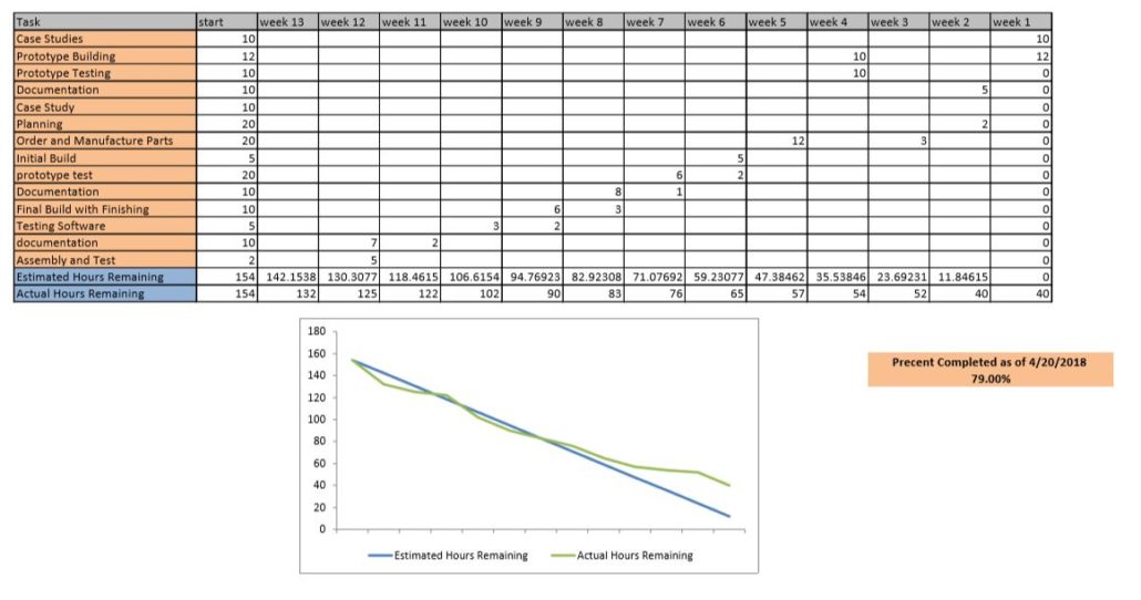
Fig.27 Burndown Chart
At the start of the semester, our team was quick and productive in submitting material and doing research for the project. Initially, the number of tasks was low and amount of time was high thus, we were more productive compared to the actual workload that was given. As the weeks passed our team fell behind as other classes also increased in workload. The increase of work, unfortunately, caused our group to fall behind on assignments that resulted in our group to work overtime during the spring break. This inrush of productivity allowed our team to regain a proper schedule by the end of our spring break.
Now that we are approaching the end of the semester we are tasked to meeting tough deadlines and yet again when looking at the breakdown chart we can see have more stuff to work on compared to the time that we have. At this time our group has developed a mutual consensus that we need to increase our productivity and work together for the success of our robot.
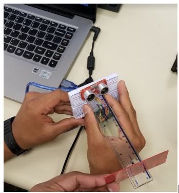
Summary of Experiments done / Rapid Prototyping Completed
By: Miguel Gonzalez (Project Manager & Manufacture)
It has been approximately eight weeks since the start of the semester and most of the first month consisted of mainly research and write-ups. But after the first month, we began experimenting with small components and sections of our BiPed. We started by looking at the legs of our robot as we knew that making the robot walk on two legs was a crucial part of our design. We created a copy of the 2016 Fall ROFI design and just focused on the legs of that robot. This initial design consisted of having 6 servo motors operating the leg and foot. Using the blog post on that robot and using help from projectbiped.com we were quick to get the robot’s leg to move. If you would like to see images and videos of the robot when it’s operating, you can view our drive folder here. In this configuration, the robot’s leg is very robust and can do very intricate movements while maintaining the robots balance. The issue with this design is that nearly 70 percent of all the weight of the robot consists of the legs alone. We knew that if we can decrease the weight on the robot we could have easier walking movements that in theory can speed up its walking speed. Our secondary design for the robot was to reduce the number of servos operating on the legs by only having four servo motors instead of six.
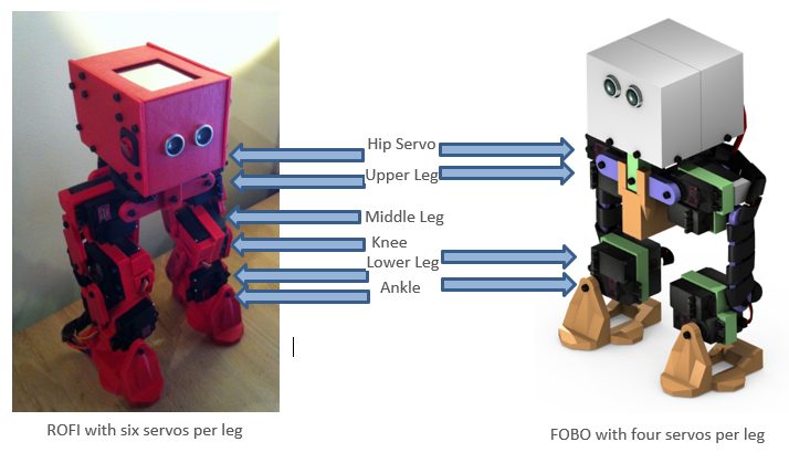
Fig.28 ROFI vs FOBO
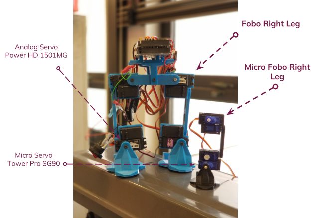
Fig.29 Original Size vs Micro Size
This newer design would remove both the knee servo and middle leg servo on both legs. Theoretically, the newer design should remain functional and provide the ability to take longer strides when walking. It is important to note that the designs for the new leg designs have been modeled and 3D printed but the test will take place on March 17, 2018. This experiment will allow us to verify that the legs can perform walking movement and maintain a higher walking speed than the six-servo design.