Spring 2018 3DoT Hexy: Getting 3DoT David Working

By: Kris Osuna (Electronics & Control Engineer) and Eduardo De La Cruz (Manufacturing Engineer)

Verified by: Eduardo De La Cruz (Project Manager and Manufacturing Engineer)

Approved by: Miguel Garcia (Quality Assurance)

Table of Contents

Introduction

Since we will be basing our design of Spring 2016’s 3DoT David, it is important that we get a good idea of how 3DoT Davids mechanism functions, as well as of how this mechanism will be interfacing with the 3DoT board and all attached peripherals.  Additionally, getting 3DoT David working will enable us to find areas that can be improved upon and may be applied as solutions in the development of our prototype. We will divide this blog post into two sections:  1. What was done by the manufacturing department and 2. What was done by E&C department.

Related Requirements

Level 2 Requirement

The robot will use a cam system identical to that of 3DoT David to drive the movement of the legs while navigating through the maze.

Manufacturing

By: Eduardo De La Cruz

Minor Repairs

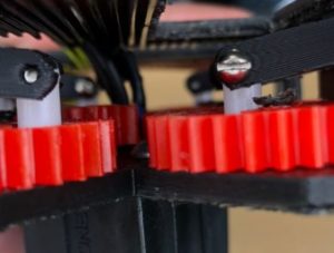
Replaced Driving Gears

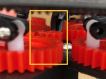
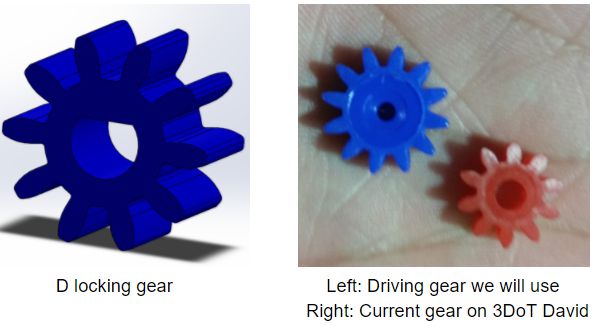
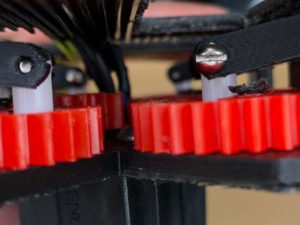
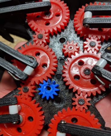
Figure 1: Added blue gears with D shaped bore 

The previous driving gears (gears tied to motor shafts)  where not turning the cam system. Therefore, a solution that the manufacturing department came up with was using gears with a smaller bore diameter and creating a D lock bore to prevent the gear from slipping from the motor shaft.  As seen above by the blue gear. 


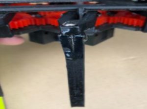
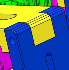
Replaced a gear shaft with a screw

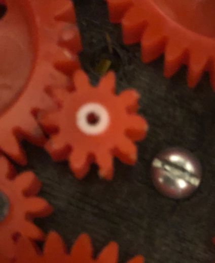
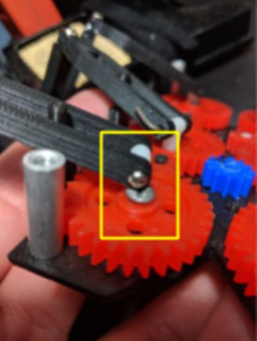
Figure 2: Added flat head screw as a replacement gear holder 

The current gear shafts are 3D printed and are very thin and fragile. A good replacement for this is a 3 mm screw with a hex nut holding it in place. To prevent the thread of the screw from messing up the gear bore, we sanded down the thread.


Added grease Figure 3: Red “N Tacky Grease 

The gears were having a hard time turning and would often lock. An attempt to fix this issue was to add Lucas Red “N” Tacky grease between the gears. Doing this actually improved cam system performance.


Conclusion

  • Need rubber tips or other material for leg tips, to prevent slipping when walking.
  • Needs better gear capture system. Current system is permanent (melting plastic gear shafts) which defies the current requirement of assembly and disassembly.

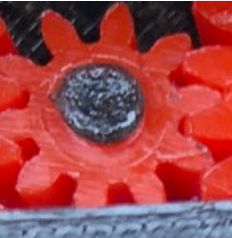
Figure 4: Melted Gear shafts 

  • Gear shafts are very fragile and can easily break. (Should pursue alternative solution than 3D printing gear shafts).  


  • Need to isolate wires from cam system. Wires susceptible to getting caught in gears Figure 5: Exposed Wires in cam 


  • Driving Gears often slip from motor shaft. Due to white insert not keeping motor shaft stiff enough. 
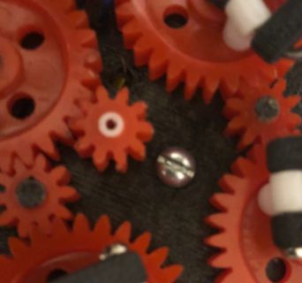
Figure 6: Current driving gears in 3DoT David 


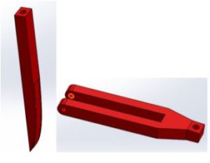
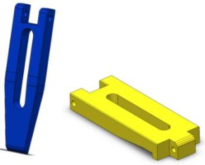
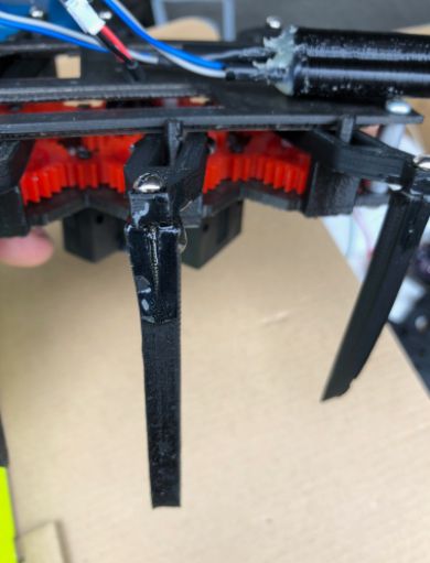
  • Femur-to-tibia joint design not very reliable. 
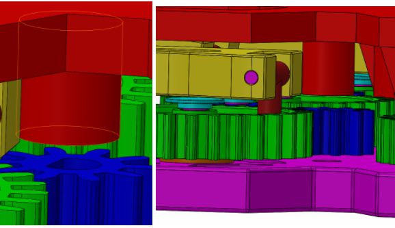
Figure 7: 3DoT David’s leg joints 


  • To reduce friction between gear shafts and gear bore, it would be interesting to pursue alternative methods to make the gears rotate with less friction, such as using bearings and bushings.

Electronics & Control

By: Kris Osuna

Since the purpose of 3DoT David was laser tag, we were unable to put to good use the custom PCB that was designed by the team. Along with this issue there was also the issue of not having a 3DoT board to interface with. As a result, the Arduino Leonardo microcontroller board was used. The Leonardo was used because it is based on the ATmega32u4, which the 3DoT board uses as well. The Arduino Leonardo technical specifications can be found under references


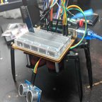
E&C attached the hardware that is used in the lab sequence robot to see if it could walk forward, in reverse, and turn around. The ultrasonic sensor was also placed on the board as well to test for obstacle detection. The bluetooth HC-06 was placed on the board to check for connectivity.


E&C tested operation of 3DoT David lab sequences 1 and 2. We were able to get 3DoT David to walk straight, turn right, turn left, detect obstacles and be controlled via a cellphone with bluetooth. The software can be found under links.


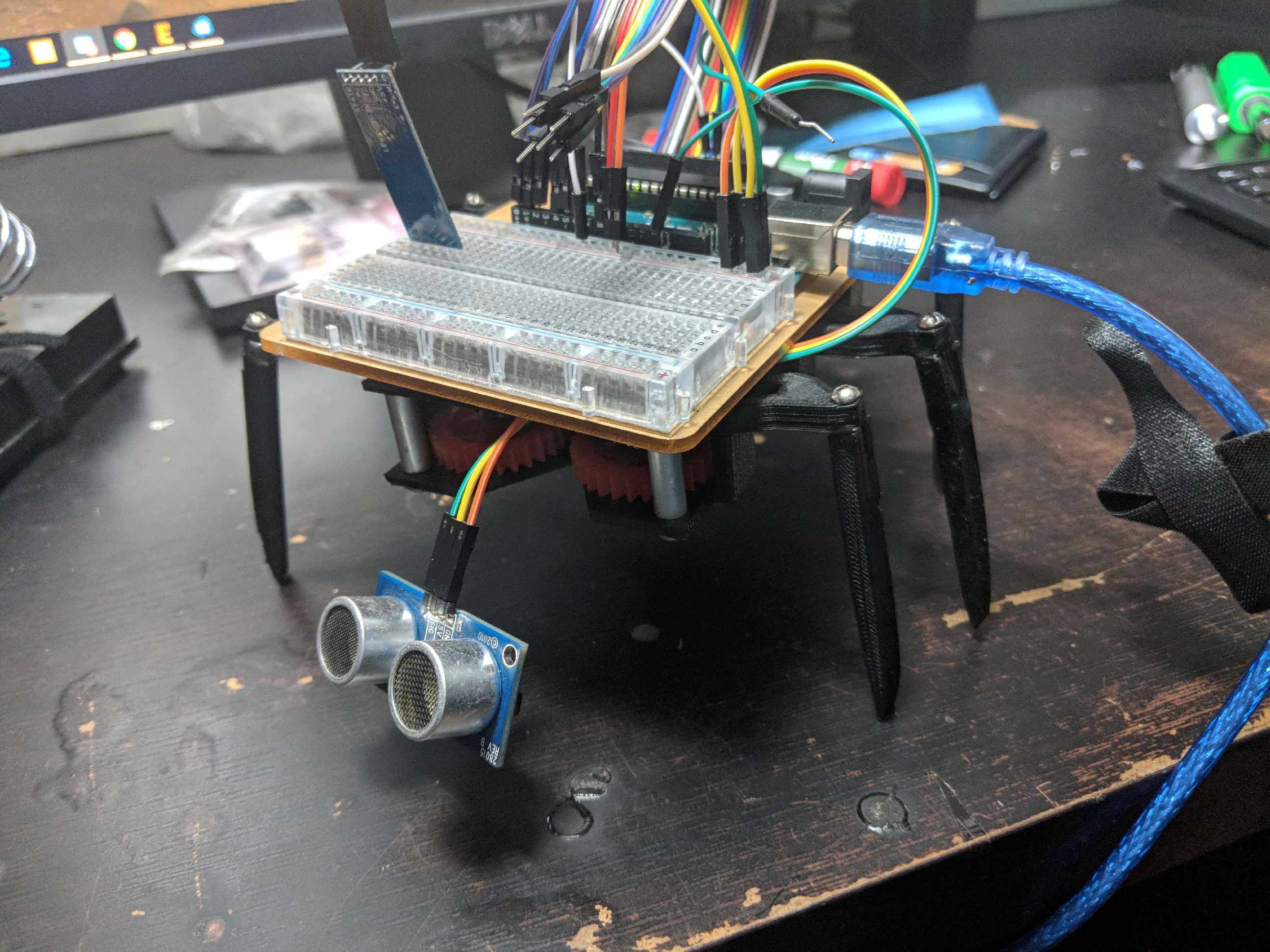
Figure 8: 3DoT David with all hardware from the lab sequence robot 

Conclusion 

The sensors we have purchased work and can be implemented on a microcontroller using an ATmega32u4. The schematic and PCB can be made with the knowledge that all the sensors can work together. Wire management is going to be an issue because the UV sensors, LEDs, and ultrasonic sensors will have to be attached to wires. Manufacturing will be notified of the wire situation to try to find a way to hide the wires. The motor wires are too short and access to the wires is difficult due to being attached to the top plate. Manufacturing will be notified of this problem.

The ultrasound drops the distance reading to 0.0 inches causing 3DoT David to run the same task twice. A condition needs to be put to ignore when the reading drops to 0.0. The Bluetooth commands were not sent through the arxterra website but through a Bluetooth app. This may be due to our Bluetooth not having BLE support. A new Bluetooth module with BLE support was purchased
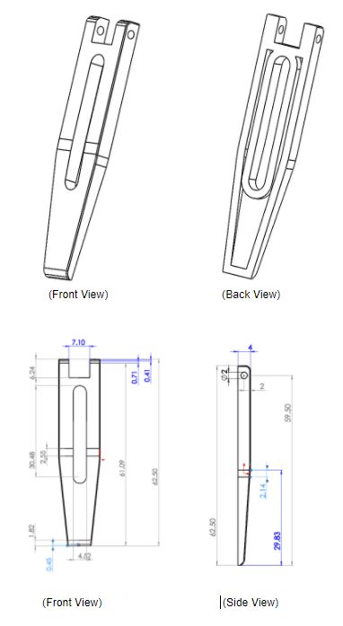
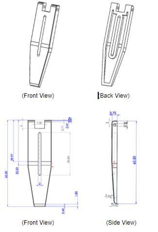
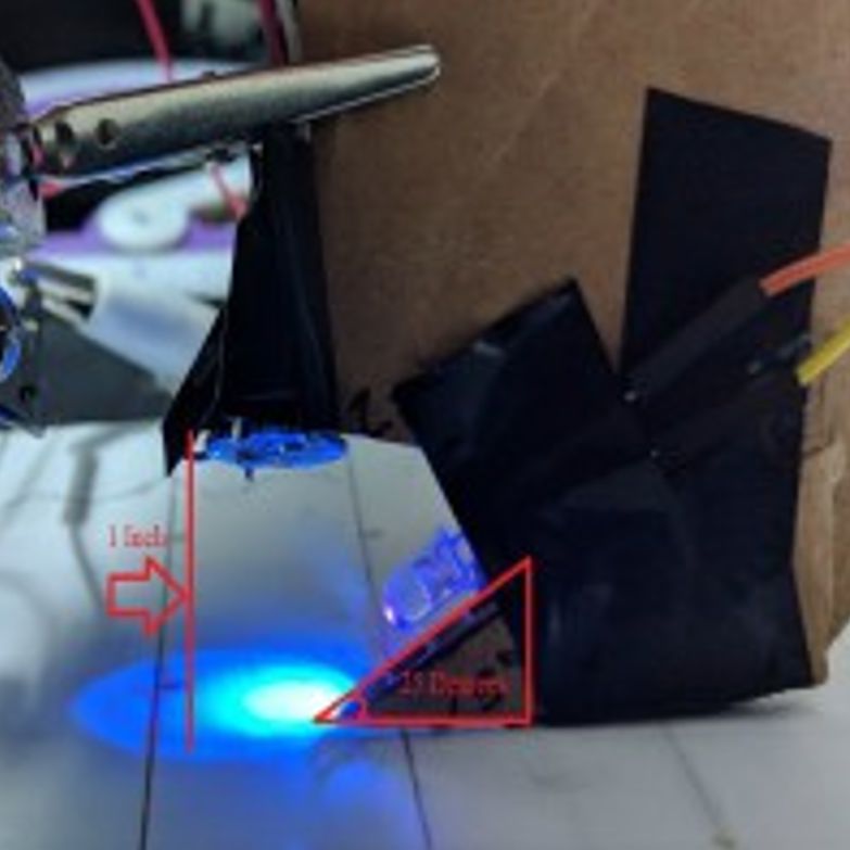
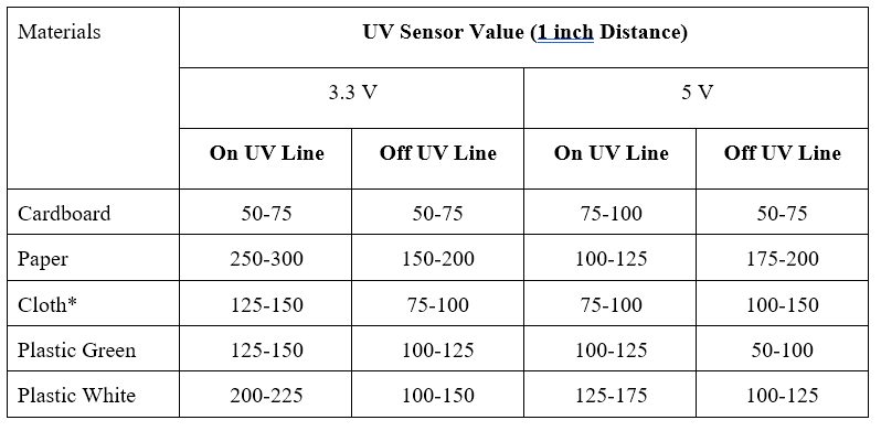
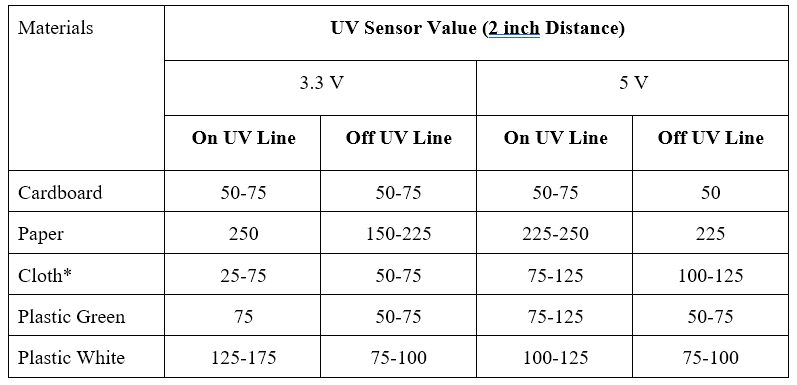
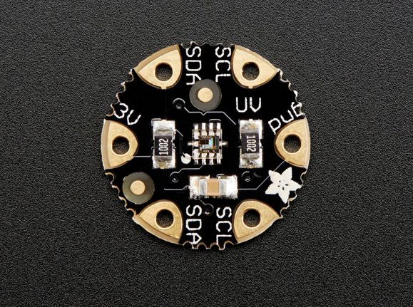
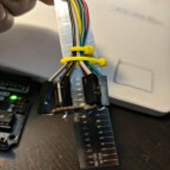
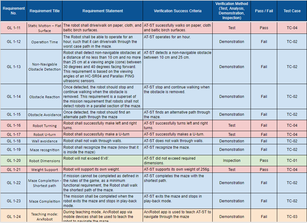
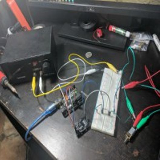
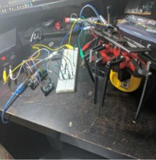
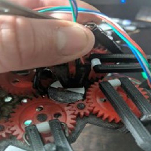
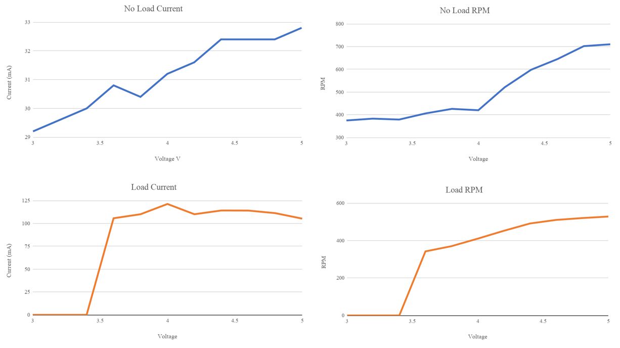
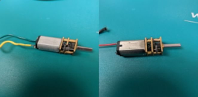
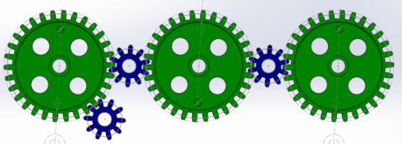
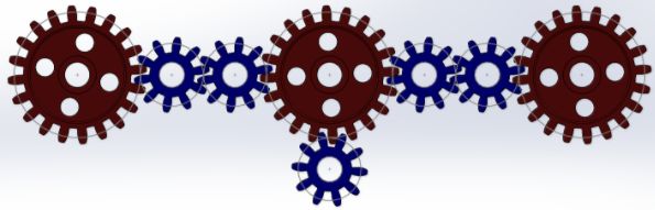
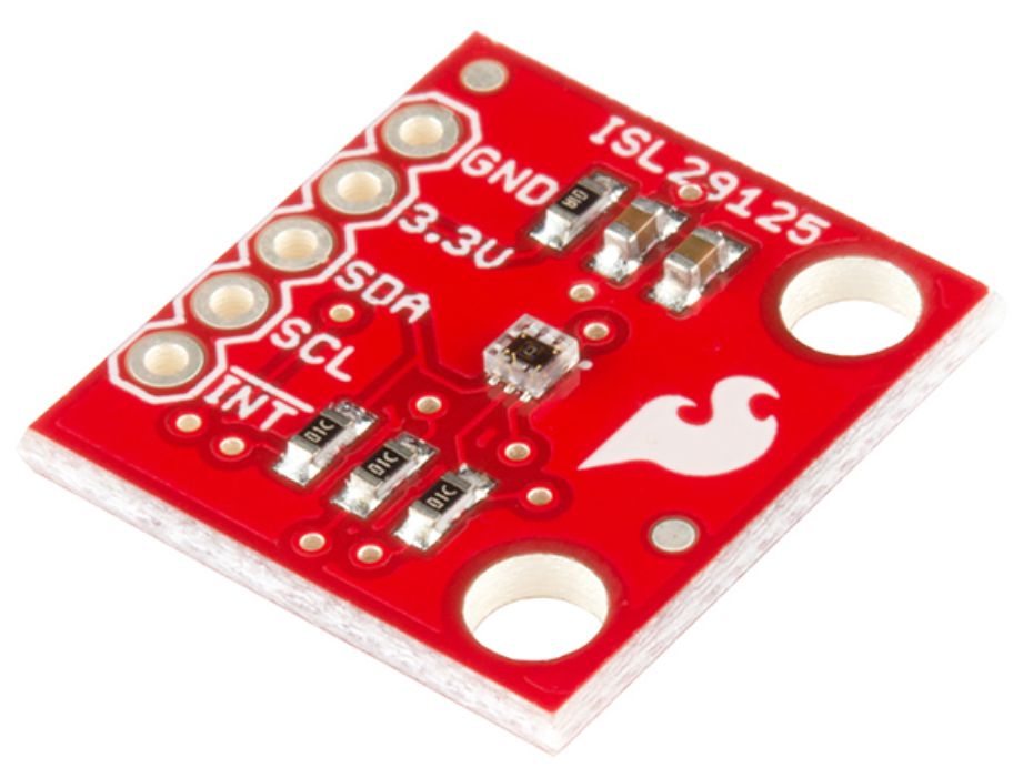
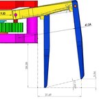
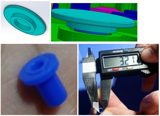
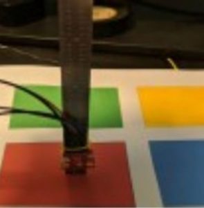
Resources

  1. https://store.arduino.cc/usa/arduino-leonardo-with-headers
  2. 3DoT David Working Code

Spring 2018 3DoT Hexy: Mechanical Drawings (Preliminary/Final)

By: Eduardo De La Cruz (Project Manager and Manufacturing Engineer)

Approved by: Miguel Garcia (Quality Assurance)

Table of Contents

Introduction

Below are the sketches for our 3DoT Hexy design. Sketches are susceptible to change. All changes will be logged in this blog post in future iterations. The first iteration will be considered our preliminary design which we label as 3DoT Hexy Mk-01. Future revisions will be labeled as iteration “n”:  3DoT Hexy Mk-0n. Note this blog post does not contain reasoning or explanation for why things look the way they are, for that you should read  Spring 2018 3DoT Hexy: 3D Model. This blog post just contains the dimensions of all components that will be 3D printed.

3DoT Hexy Mk-02 (Final Design) – (April 28, 2018)

Chassis

Bottom Panel 

Figure 1: Bottom Plate Dimensions

Top Panel 

Figure 2: Top Plate Dimensions 

Femurs

3 Types of Femurs 

Figure 3: Three Types of Femurs 


Middle Femur Dimensions 

Figure 4: Middle Femur Dimensions

Outer Femurs Dimensions

Figure 5: Front Femur Dimensions 

Note: The back leg will have the same measurements with extrude-cut on opposite side.

Figure 6: Side View of femurs split in half showing Leg lifting ramp

Tibias

Figure 7: Tibia Dimensions

Femur-to-Gear Joints

Figure 8: Femur-to-Gear Joint Dimensions

Sensors Enclosure

Figure 9: Sensor Enclosure 

Figure 10: Front and Back View Dimensions 

Figure 11: Top and Bottom View Dimensions 


Figure 12: Side View Dimensions 


Figure 13: Front Split in half view  

Hardware Enclosure

Figure 14: Hardware Enclosure 

Figure 15: Side View Dimensions 

Figure 16: Top View Dimensions 

Figure 17: Split in Half View 

Wire Tube

Figure 18: Wire Tube Dimensions 

3DoT Hexy Mk-01 (Prototype) – (March 15, 2018)


Chassis

Bottom Panel

Figure 19: Bottom plate dimensions 

Top Panel

Figure 20: Top plate dimensions 

Femurs

3 Types of Femurs 

Middle leg                       Outer Legs

Figure 21: Femur Dimensions

Note: The back leg will have the same measurements with extrude-cut on opposite side.  


For all 3 femurs

Figure 22: Section view of leg lifting ramp in femurs


Tibias

4 Outer Tibia

Figure 23: Outer Tibia Dimensions 

2 Inner Tibia

Figure 24: Inner Tibia Dimensions 

T-Joints (Gear-to-Femur Joints)

The T-Joints will connect the gears to the femur using 2.5 mm screws

Figure 25: Dimensions of T-joints 

Spring 2018 3DoT Hexy: Project Planning and Scheduling

By: Eduardo De La Cruz (Project Manager and Manufacturing Engineer)

Approved by: Miguel Garcia (Quality Assurance)

Table of Contents

Introduction

The purpose of this post is to compile the project schedule from start to finish for all task that need to be finished by each division. The schedule will practically mirror the time frames and due dates priorly established in the task matrix. The goal is to provide a visual reference of how far or close one is from reaching their deadlines for a given task. We will begin by first taking into account the time spent hiring, planning, and learning about the engineering method, then we will be breaking down the time frame it will take each division to complete their task, and lastly we will compile all this information into a project schedule using excel’s Gantt project planner.

Final Project Schedule (May 15, 2018)

Figure 1: Final Schedule 

Note: Task Labeled in red are task we never got too. Purple are task completed in time. Dark yellow are task completed past the due date. Light purple and light yellow are task that where never completed.

Figure 2: Final Burndown 

Blue = Current Progress, Orange = Desired Progress

From the burndown above, we can see that we ended up being 10 task behind.  Most of these task were related to hardware testing and software.

Links to:

Final Schedule:

Planner Final2.0

Final Burndown:

burndown

Preliminary Design Project Schedule (March 15, 2018)

Figure 1 : Project planner generated using excel’s Gantt project planner)

Dark purple represents our progress, light purple represents what needs to be done. If we exceed the due date the bar will turn orange. Orange lets us know how many days it was late.

Task for each division are color coded and their is a legend at the top explaining each color.

Note: Division members may take on task from other divisions if they see that they have the time available in their existing schedules to aid other divisions in getting their task done.


To get a closer look at the specific task in the above project planner, look at the excel spread sheet located in Resources.

Stage 1: Hiring & Picking a Project, Learning the Engineering Method, and Developing a Task Matrix

Week 1: Hiring & Picking a Project

    During this week students are introduced to the EE400D robot company, to all job positions available, and to the 6 projects that can be created. Students submit resumes and cover letters applying for a specific roles, form teams, and pick a project to tackle.

Week 2 – 3: Learning the Engineering Method

During this week students are introduced to a series of presentations that cover the engineering method. This method is a systematic approach used to reach a desired solution to a problem. Students will learn the six steps: developing ideas, concepts, planning, designing, development, and launching. Students will present a presentation on creativity development at anytime during these weeks. During this time we also develop project mission and level 1 requirements.  

Week 4 – 5: Developing a Task Matrix

Students will read existing blog post from previous semesters, scavenge for what can be reused and develop their own task matrix. The task matrix will require extensive research on what needs to be done by each division to make the project happen. The task matrix requires that students provide for each task: existing references, define what is its predecessor and what it is linked to, who will the task be assigned to, estimated time to complete, and the due date.

Stage 2: Division Specific Task

    From week 6 and onwards, each division will focus on completing task that are specific to their job description and that should already be defined in the task matrix.

Project Manager

Week 6

Preliminary Budget, Maze Definition

Week 7

Additional Robot Specific Mission Objectives, Planning & Scheduling, Work Breakdown structure.

Week 8

Preliminary Design Review Blog Post.

Week 9 – 15

Work on keeping everyone on schedule, work on Project Video, regularly update professor about progress, inform team members about changes, upload blog post.

Week 16

Final Blog Post, lessons learned.

Week 17

Project Video.

Mission, System, & Testing

Week 6

Project Specific Lvl. 1 & Lvl. 2 requirements.

Week 7

Verification Test Plan and Report, System Block Diagram, Product Breakdown Structure, Interface Matrix, Resource Report (Mass, Power, & Cost) , Robot Avoidance rules (Update), UV sensors.

Week 8

3D print times (preliminary), Mass (Preliminary), Preliminary Design Review Blog Post.

Week 9

cable tree and assembly diagram

Week 10 – 14

Work with E&C in implementing cable tree, system wiring, PCB layout, updating mass, power, and cost report, and creating the arxterra custom commands and telemetry on the App and Arduino.

Week 15

Final System Integration and Test.

Week 16

Final Verification.

Week 17

Execute mission

Electronics & Control

Week 6

Decision on Motor type selection.

Week 7

Prototype Fritzing Diagram, Power Estimate of Components, UV sensors study, RGB color sensors.

Week 8

Preliminary Design Review Blog Post, getting 3DoT David working.

Week 9

System Schematics (Eagle CAD), Sensor shield layout.

Week 10

Breadboard build and test.

Week 11

Integration Testing on final design, Electronic Component BOM and Order, Spiderbot line following code and demonstration.

Week 12

Robot avoidance general detailed algorithm, Spiderbot turning code and demonstration.  

Week 13

whichway code and demonstration, custom PCB Assembly and Fabrication

Week 14

Implementing robot avoidance code, Interfacing with 3DoT David or our model.

Week 15

Final Arduino Code, Final system Integration and testing.

Week 16

Last minute touch ups.   

Week 17

Execute mission

Manufacturing

Week 6

Research and obtain a reference model (Spring 2016:3DoT david design) from which to model your movement mechanism (not a task)   

Week 7

Mechanical Drawing, Decision on movement mechanism to implement, Determining gear design

Week 8

Improving 3DoT David Design, Preliminary sketch, Preliminary Design Review Blog Post  

Week 9

3D solidworks model

Week 10

stress testing  

Week 11

Decision on materials and fabrication methods, Manufacturing Prototype.

Week 12 – 13

Revisions, fabrication and assembly of PCB.    

Week 14

Final 3D Model.  

Week 15 – 17  

Aid in other task, last minute revisions on design (if any).

Preliminary Burndown (March 15, 2018)

The graph shows how task will be distributed over the course of the semester. The goal is to finish all task before execution of the mission.

Figure 2: Preliminary Burndown

Blue = Current Progress, Orange = Desired Progress

As off week 8, we have completed about half of the task defined in the task matrix. So far, we have submitted most if not all preliminary task documentations, and a few trade studies done by each division engineer showing their progress. For more details on what is due each week based on the above burndown read, “Spring 2018 3DoT Hexy: Project Planning and Scheduling”.

Resources

  1. https//drive.google.com/drive/folders/1XX5b3j3zwPvR-v6-B63a0Ad5g8Auu3_Y
  2. https://www.arxterra.com/wp-content/uploads/2018/04/Planner-Final2.0.xlsx