Gear Studies

Written by Railan Oviedo (Manufacturing)

Objective

For the Pete-Bot’s (P-Bot) method of movement, our project has implemented a
planetary gear system that incorporates the incline gear as the wheel and 3 planetary gears. The top planetary gear will be the driving gear that is connected to the GM6 motor, while the other two planetary gears will have ball bearings inserted into them—effectively making their presence their solely for the purpose of properly spacing the incline gear. In order to ensure the whole structure stays together, washers will be placed to prevent them from touching the chassis, and a triangular gear holder will be utilized to prevent the system from popping off the chassis.

Preliminary

For a planetary gear system to work, specific parameters must be made in order to ensure the gears can smoothly spin together. The equations to ensure this are as follows:

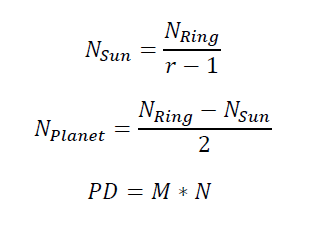
Equations (1) to (3) to determine the number of teeth for the gears and pitch diameter

“N” represents the number of teeth for the incline gear ring, the planetary gears, and the sun gear. As stated in the introduction, the sun gear will not actually be implemented, but it is still necessary for designing purposes. The variable “r” is for the ratio of revolutions between the sun gear and the incline gear.

The Pitch Diameter “PD” is the effective diameter of the gears, and it is determined by multiplying the number of teeth by the gear module “M.” The modules must be the same for all the gears in the system in order for them to operate smoothly.

Test 1

The initial “r” value chosen for the system was 3, so the sun gear would spin 3 times for every spin of the incline gear. The modules have been set to 1, so the number of teeth also determines the pitch diameter in millimeters. For the first trial, the incline gear was chosen to have 40 teeth – thus resulting in a 40 mm pitch diameter – with an outer diameter of 45 mm. From the equations, the other parameters were found as the following:

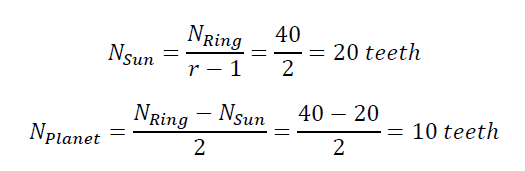
Equations (4) & (5) that show the number of teeth calculated

With this, SolidWorks was used in order to generate a simulation for the gears.

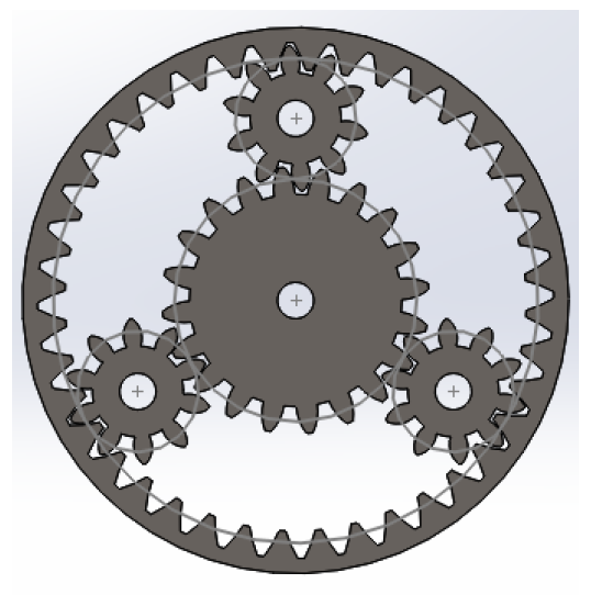
Image One – Initial Gear System

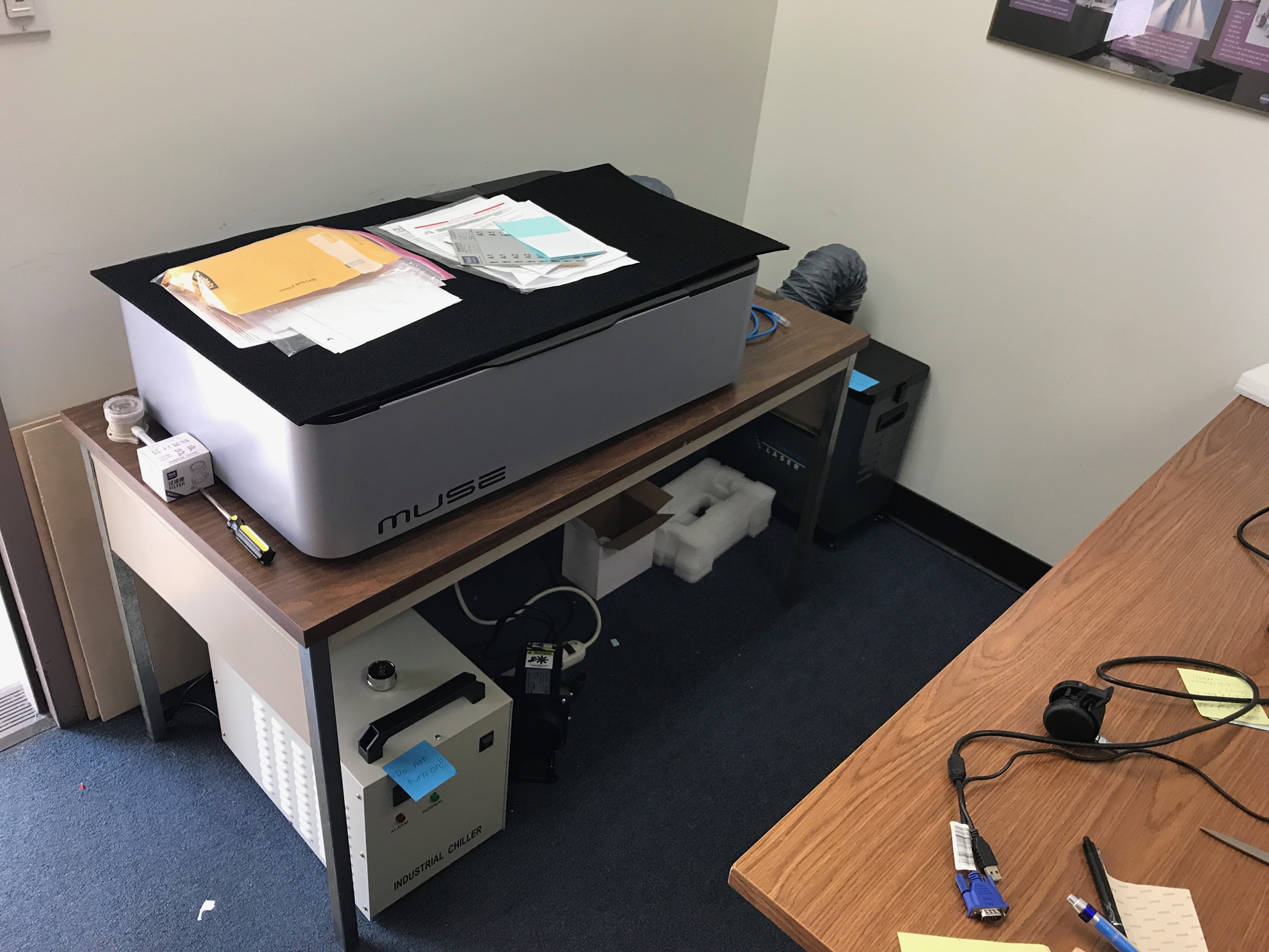
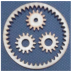
Because of the ball bearings, the lower planetary gears will have an increased inner diamater of 1/4 of an inch. This system was laser cut in order to rapid prototype with the P-Bot chassis.

Video Link

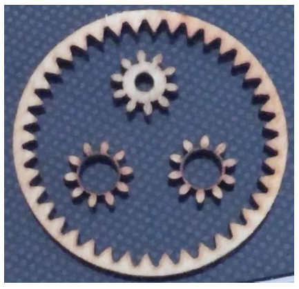
Image Two – Initial Wooden Gears

Gear Holder

The gear holder was made to fit the shape of the first gear system. The design is shown in the picture below:

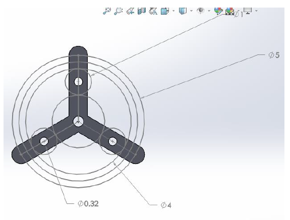
Image Three – Gear Holder

The measurement numbers are given in centimeters. The 4 cm diameter circle represents the pitch diameter of the incline gear, and the 5 cm diameter circle reqpresents the total diameter of the wheel including the tire treads.

Test 2

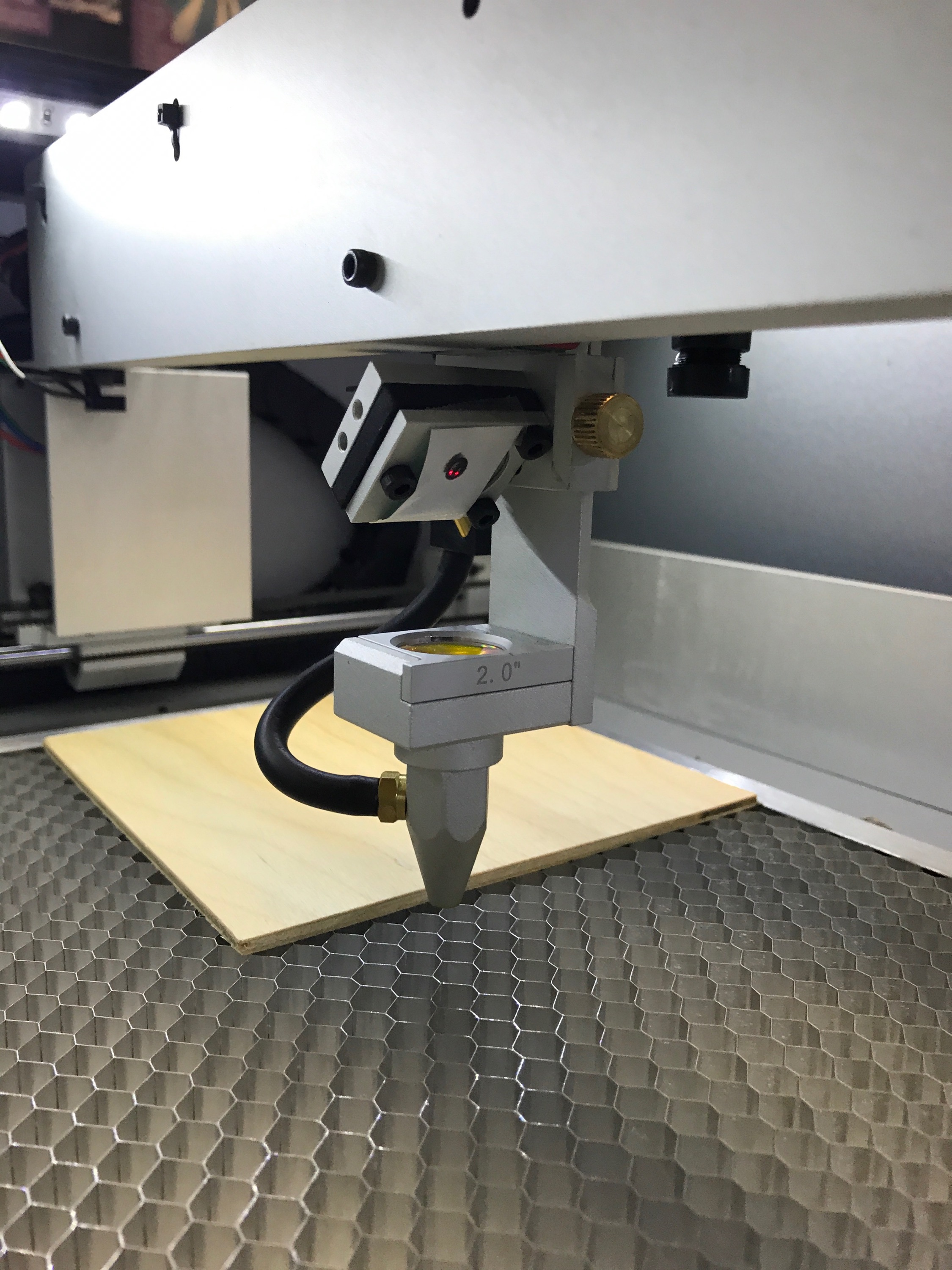
After testing how the ring actually functions on the chassis, it was seen that the planetary gears for the ball bearings are incredibly flimsy. Furthermore, the wheel is not large enough to surpass the bottom of the chasis, as shown in the picture below:

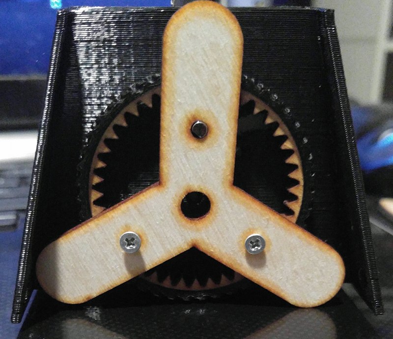
Image Four – Rapid Prototype Implementation of Incline Gear

Due to this, a new system that utilizes a 42-teeth incline gear with “r” equal to 4 was used in order to increase the diameter of the wheel. From the equations, the other gears’ teeth were found as:

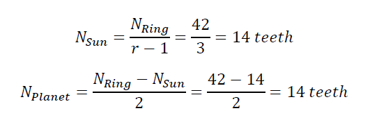
Equations (6) & (7) show the new number of teeth determined for the new gear system

Since the planetary gears will now have a wider pitch diameter, this should eliminate the issue of their stability for the ball bearings. Using this, another SolidWorks model was made, and these were also laser cut for rapid prototyping.

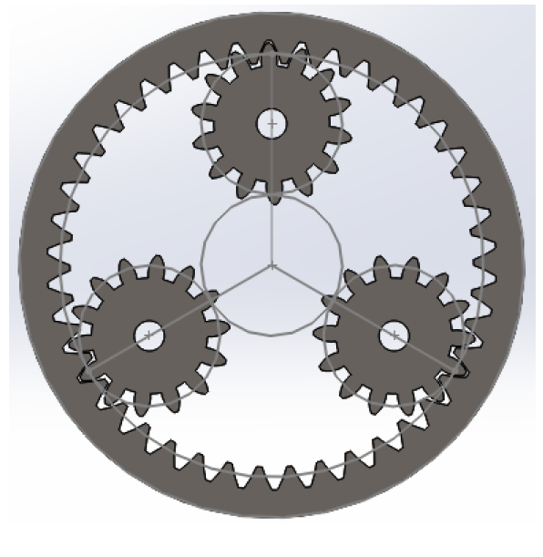
Image Five – Second Gear System

Image Six – Second Set of Wooden Gears

Results

After trying the alignment pattern of the gears for Test 2, it was found that the incline gear ring would not touch the driving planetary gear due to the fact that the incline gear becomes slightly raised when it is placed on the ground.

However, when attempting to use the 14 teeth gears in tandem with the alignment for Test 1 (Refer to Image 1), it was discovered that the gears were very close to being in the perfect spots for the whole system to function properly. Minor tweaks would need to be made on this alignment in order to get the positioning correct.

Test 3

The third and final test was to adjust the alignment from Image 1, and to then use the 14 teeth gears in place of the actual gears that should be used for it (i.e. 10 teeth planetary gears, and 20 teeth sun gear).

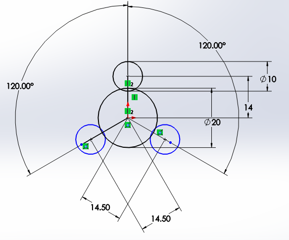
Image Seven – SolidWords Model for Test 3 (in mm.)

The original distance between a planetary gear and the sun gear was 15mm. This distance is reduced in the hopes of having the incline gear ring fit. To test whether this would work, the alignment pattern was cut out onto wood via a laser cutter.

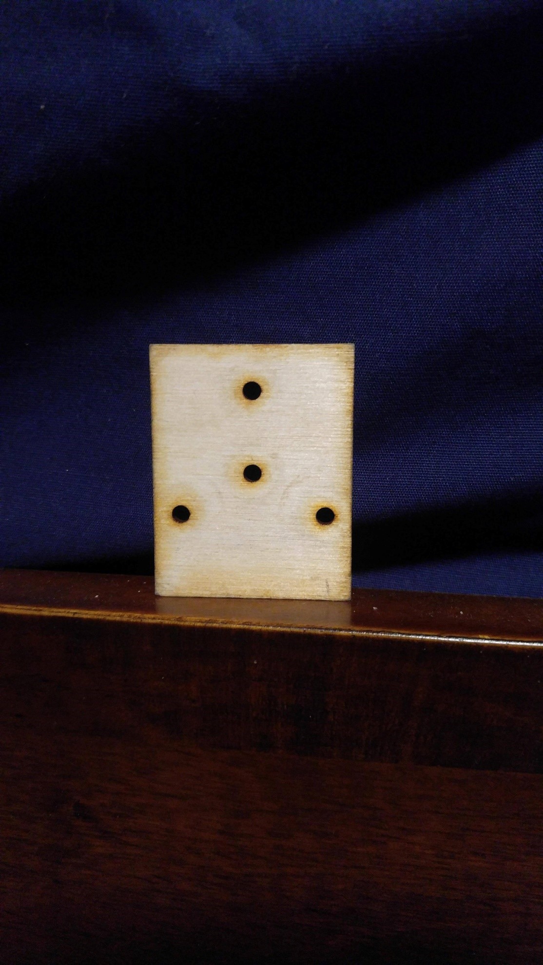
Image Eight – Test 3 Alignment Cut-Out on Wood

The gear holder was also altered to fit this new alignment. The sides were made thinner so it is possible to see the gears behind it, and a slit was added to one side in order to indicate which side connected to the driving planetary gear. This side was also made slightly longer than the others in order to accommodate the fact that the incline gear slightly rises when it is on the ground.

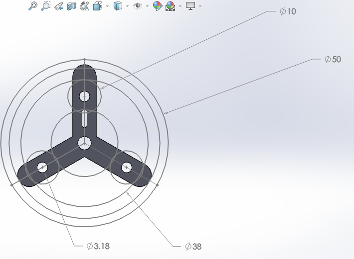
Image Nine – Gear Holder for Test 3 (in mm.)

After laser cutting out the gear holder, the alignment pattern was tested and confirmed to work extremely well. Small washers were put in place between the wooden plate and the gears, and between the gears and the gear holder. These washers were small enough so that they only come into contact with the bearings inserted into the gears, thus resulting in a very small amount of friction when trying to spin the incline gear. The assembled pattern and a reference video are given below:

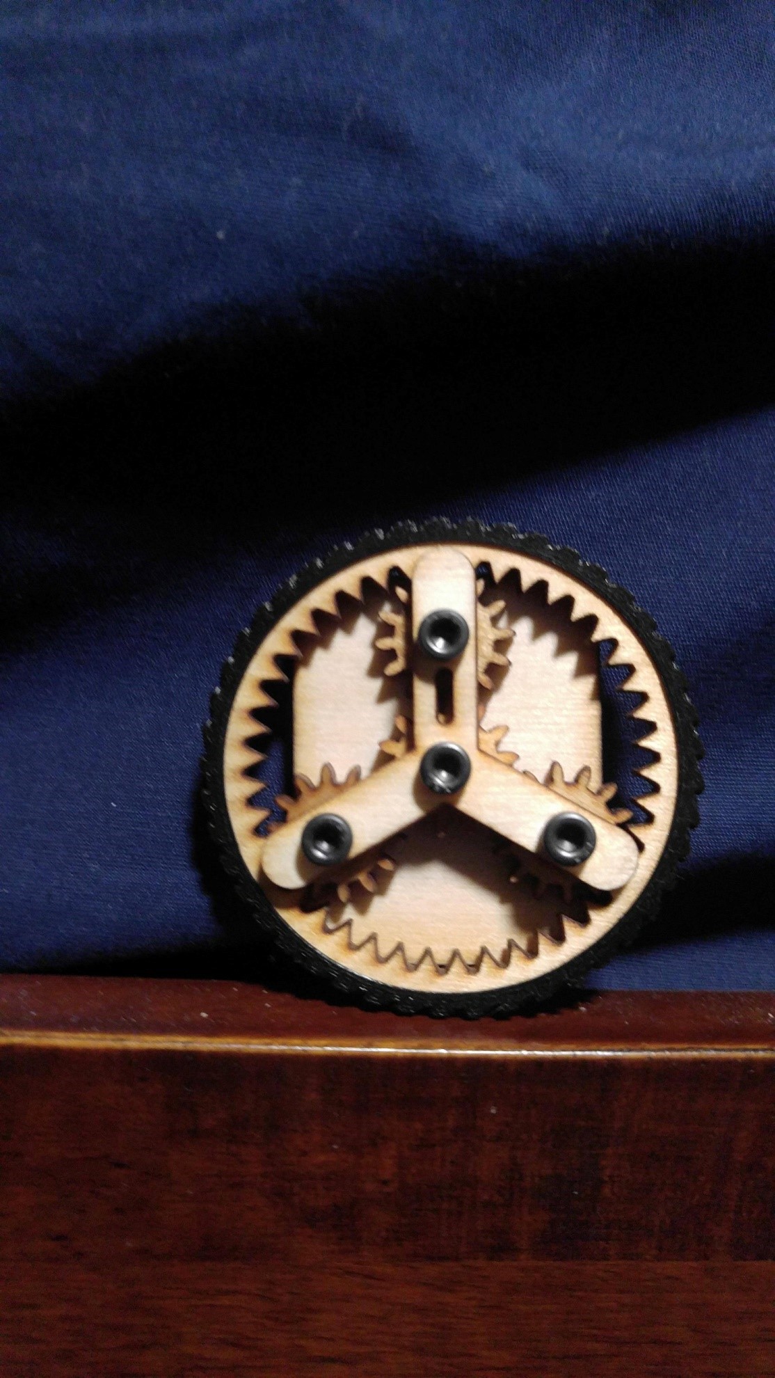
Image Ten – Test 3 Alignment Assembled with Gears

Video Link

D-Gear

Although the alignment was set, it now became necessary to change the driving planetary gear so that it fits the shape of the new GM6 motor shaft, which has a D-shaped profile. The model for this gear is given below:

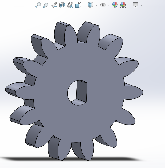
Image Eleven – D-Gear

With the alignment set and the D-Gear created, it was then implemented onto the chassis itself, and can be seen as:

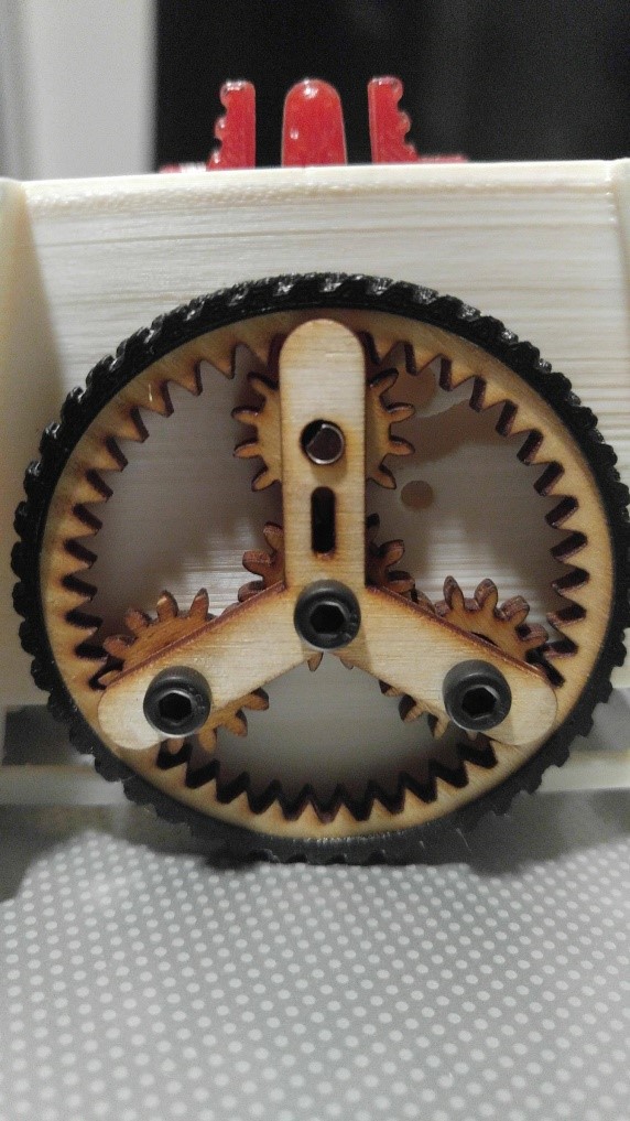
Image Twelve – Assembled Planetary Gear System

References

[1] Reference One

ModWheels 3DoT v 5.03 Integration and Test

By: Lucas Gutierrez (Project Manager) & Matt Shellhammer (Electronics & Control Engineer)

12/12/2017

As of Tuesday, December 12th, 2017, ModWheels does not have an operational v. 5.03 3DoT.  ModWheels was given a v. 5.03 on Monday, December 11th, 2017 without a Bluetooth module (HM-11) or a battery holder.  After soldering the HM-11 and battery holder, a test was done and motors and peripheral subsystems encoders could not be powered simultaneously.  Due to this, along with the HM-11 being inoperable, ModWheels decided to revert back to the SparkFun ProMicro microcontroller for continued prototyping until 3DoT issues have been resolved.

11/19/2017

To fulfill the customer’s request, ModWheels will incorporate the 3DoT as its choice for a micro-controller.  As of 11/15/2017, the most recent EE 400D class, the 3DoT v 5.03 was available for in-class testing.  When the 3DoT v 5.03 becomes available for long term usage, a more thorough blog post will cover its the testing and integration with respect to the ModWheels project.

ModWheels Custom Command and Telemetry

By: Lucas Gutierrez (Project Manager)


Discussion

An important aspect in fulfilling ModWheel’s mission requirements is integration with the Arxterra platform, both with the phone application and web based application.  To tailor and customize the user experience of the Arxterra applications to the ModWheels project, a few custom commands and telemetry will be incorporated. ModWheels would have implemented a 4 state custom command on the Arxterra GUI.  These states would have been RC (user controlled), Memory (Navigate with user), Replay (autonomous navigation), and Phase 2 (avoiding robots). RC mode would allow the user to control the ModWheels toy robot with the given slider options (motor). Memory would be a navigation of the maze with the user guiding the robot to the end of the maze. Replay would be the autonomous navigation of the maze based off Memory mode. Phase 2 would deal with avoiding robots in the maze. A new slider widget should be requested to allow for direct control of the servo on the ModWheel toy robot. The issues that arose revolving the 3DoT board made it difficult to test Arxterra on our toy robot.  Future teams that do decide to adopt this project should collaborate with Jeff Gomes when dealing with the Arxterra GUI.  Custom gadgets can be implemented that could make controlling the toy robot easier.

Custom Commands

RC Mode

Inside the maze

D-pad will be used to call predefined turn subroutines.

Outside of the maze

D-pad

Forward: Increase speed from current speed to 255.

Left: Move servo to left when pressed and move back to center when button is released.

Right: Move servo to right when pressed and move back to center when button is released.

Back: Decrease motor speed from current speed to 0.

Autonomous Mode

Make predefined turns based on recorded data.

Telemetry

  • Battery level indicator.
  • Robot orientation (when using web based application).
  • Direction (when using web based application).
  • Current room (when using web based application).

PeteBot Requirements

(Written by Elizabeth Nguyen (Project Manager) & Melwin Pakpahan (Missions, Systems, & Test)

Table of Contents

Objective

The requirements for the PeteBot (3DoT Chassis) are defined at two levels and provide the team with direction and to determine what shall be accomplished. Verification and validation are also outlined.

Current Status:

At this time, not all requirements have been confirmed and are pending approval. Some of the requirements listed below are different from the requirements listed in the PDD.

Level One Requirements

Program Requirements

  1. PeteBot shall be completed by Wednesday, December 13, 2017.
    1. This requirement coincides with the last day of class.
    2. This is the projected demonstration date for all toy robots.
  2. PeteBot shall cost no more than $200 as projected by the customer.
  3. PeteBot will be a toy robot.
    1. This requirement is defined through the customer expectations.

Project Requirements

  1. PeteBot shall use the PBX11 which is an alternative microcontroller to the 3DoT Board that utilizes the SAMB11 chip instead of the ATMega32U4 chip.
    1. In case the PBX11 board is inoperable, the 3DoT Board shall be used in its place.
  2. PeteBot shall navigate through a maze with remote control through the ArxRobot App or the Arxterra Control (based on Project and Mission Objectives).
  3. PeteBot shall be no larger than 4 x 3.5 x 3 inches.
    1. These measurements were taken at the widest dimensions of the chassis since it tapers at the bottom.
  4. PeteBot shall be able to memorize a path through the maze that is taught by the user (based on Project and Mission Objectives).
  5. PeteBot shall be able to autonomously travel down the path that was memorized (based on Project and Mission Objectives).
  6. PeteBot should be able to navigate the maze and avoid collisions when multiple robots are in the maze.
    1. The Rules of the Maze for the avoidance algorithm have been defined.
    2. Line following will be implemented if the motoer encoders are funtional.
  7. PeteBot shall have a chassis that is 3D printed.
    1. This is derived from a customer expectation.
  8. The total 3D print time of PeteBot’s chassis shall not exceed 2 hours (based on Project and Mission Objectives).
  9. The main body (chassis) of PeteBot shall be of one solid piece.
  10. PeteBot shall be assembled per the guidelines of Disassembly and Reassembly.
  11. The PeteBot Paper Shell shall resemble the CSULB mascot, Prospector Pete.
    1. This is a customer expectation.
  12. The PeteBot shall be able to perform all functions as programmed by the Arxterra app.
    1. This includes custom commands.

Level Two Requirements

System Requirements

  1. PeteBot shall operate for no less than 20 minutes using a fully charged battery.
  2. PeteBot shall attain an operating speed no slower than 3 centimeters per second.
    1. This speed is referenced from Mission Duration.
  3. PeteBot shall utilize the Generic Color Sensor Shield for line-following.
  4. The PBX11 board shall fulfill the requirement to be a custom PCB.

Subsystem Requirements

  1. PeteBot shall be powered by a RCR123A Lithium Polymer battery.
  2. PeteBot shall use a planetary gear system.
  3. The Generic Color Sensor Shield shall be located at the front of the PeteBot.
  4. PeteBot shall have a castor wheel under the Generic Color Sensor Shield to support the mobile phone.
  5. PeteBot shall utilize two GM6 brushed DC motors with an extended D-shaped shaft.
  6. PeteBot shall utilize two shaft encoders for line following.

Generic Color Sensor Requirements

Written by Charles Banuelos (Manufacturing and Design;Division Manager)

& Muhannad Al Mohamed (Electronic & Control Division Manager)

Worked on by Charles Banuelos (Manufacturing and Design;Division Manager) & Muhannad Al Mohamed (Electronic & Control Division Manager)


The Color Sensor Shield shall provide measurements from two color sensors with different I2C addresses.

The Color Sensor Shield shall be compatible with any Fall 2017 400D robot. (Specifically to avoid the caster wheel of PBot )

The Color Sensor Shield will use a generic 90 degree pin header to interface with the microcontroller.

The Color Sensor Shield shall use parts of 0603 (imperial) package size or larger.

The Color Sensor Shield will be compatible with any version 5.03 3Dot board.

The Color Sensor Shield will be 55 mm in length.

The distance from the outer edge of a color sensor IC to the other outer edge of the second IC will be 40.249 mm.

The White LEDs will be 2.76 mm away from each color sensor IC edge to edge.

The Color Sensor Shield will be 10.85 mm in width.

Generic Color Sensor Board Dimensions


Training on Arxterra 3DoT App RC Mode

Written By: Muhannad Al Mohamed (E&C DM)

Table of Contents

Objective

The Arxterra 3DoT App training had a goal of teaching E&C and MST members how to use their phones to communicate with their projects through Remote Control Mode. The ArxRobot Application has two different modes of communication with the Robot’s Microcontroller. The Remote Control Mode (covered in this training) and the Community mode (Covered in the next training session). The user, through the ArxRobot App, should be able to send commands to the microcontroller either through predefined commands or custom made ones.

Introduction

The communication in the RC mode is done wirelessly through Bluetooth with an easy pairing process at the initialization of the RC mode. Commands are sent to the microcontroller as packets that consist of bytes that have specific identifiers to indicates whether the command is a command or telemetry. The packets contain data bytes that can be processed by the pre-coded microcontroller.

User’s Interface

The user interface in the RC mode is user-friendly. The default setting shows the controls of two motors in a strip type command. The strip can be changed to a D-pad looking control. Custom commands can be set to show on the user’s interface when enabled.

During the training session, members were taught how to use the user interface to control motors by giving specific input, moving motors at the same time, and steering trim to maintain desired speeds.

ArxRobot App’s Settings

The commands used in the app can be changed in the settings of the app. To access the predefined and custom commands users needed to be in Developer Mode.

The Phone Configuration window in the setting enables the user to choose the way to connect to 3DoT board, show phone’s battery percentage on Control Panel, and flip Camera’s position.

The predefined commands are commands and telemetry functions defined by the Robot3DoTBoard and saved in the app as default commands to operate a Mar’s Rover. These commands, if needed, can be used by the user by enabling each command in the Robot Capabilities configuration.

The Custom Command & Telemetry Configuration window allows the user to create new commands to be sent the 3DoT Board and receive Telemetry from it.


Custom Commands & Telemetry

Options for commands and telemetry is created by adding an option and giving it a specific address from (0x40) to (0x5F). Each option should be chosen to be either for commands to be sent to the 3DoT or Telemetry to be sent by the 3DoT. Commands can be controlled by the ArxRobot App; however, not all telemetry options are shown on the app. Each option should be enabled to show in either RC mode or Community Mode.


There are 7 options the user can choose while creating a custom command:

1- Boolean:

This option enables the user to send a byte in the data packet to the 3DoT board with a value of either (0x00) or (0x01). In the user’s interface, it can be seen as a switch that can be changed. The user can choose a default value of either of the previous options. This option can be used to turn an LED on and off for example.

2- Select:

This option enables the user to have multiple outputs to switch to. It is similar to the Boolean switch; however, it can have as many options the user wants to switch into. It sends a 1 byte of data parameter with the packet that is sent to 3DoT board; however, the values sent can be modified by the user. The select option shows in the user’s interface as radio buttons.

3- Byte:

This option can be used to send a byte in the data packet but with a wide range that can be changed by the user. It has a default range from -127 to 128 where the user can control which value sent by moving a strip in the user’s interface. These values can be changed by the user in the Byte settings to the desired range but it would still be a byte range. The steps between each value can be modified as well. This option can be used to move a servo motor for example.

4- Unsigned Byte:

This option is similar to the Byte command. The only difference would be the default range that starts from 0 up to 255.

5- Short:

This option is also similar to the Byte/Unsigned Byte; however, this option sends two bytes in data packet. Because it sends two bytes, the short command has a wider range than Byte/Unsigned Byte. The default value of this options ranges from -32768 to 32767.

6- Unsigned Byte:

This option is similar to the short option; however, the default range for it goes from 0 to 65535.

7- Header/Separator:

This option does not send any data in packets sent to the 3DoT; however, it is used to make the interface more user-friendly. titles to commands can be given using this option and it can be used to as separator if it was used without writing anything to it.

Training document

Arxterra RC Mode training document can found at this link.

Optimizing RC Mode in Projects

Update: 12/5/2017

Room Showing Telemetry Command

By creating custom commands and telemetry, engineers can create commands that can enable them to control their projects through the maze. For example, the path taken by a robot can be sent back to the phone connected to the MCU using telemetry options to show which room the robot is in on the phone’s display using RC mode. By optimizing the translated code from EE346/EE444 written by Mark Huffman (Goliath Project Manager) and Matt Shellhammer (ModWheels E&C Engineer), the variable “room” value can be sent as telemetry to the ArxRobot app. In the ArxRobot app, a telemetry Select command should be created and called room where it shows the byte value on the phone.

Creating Telemetry command called Room

Selec command Room

Assigned options to show the room type as implemented from the maze

Room type is shown in RC mode interface

Phase Selecting Command

The same process can be implemented to apply choosing the phase each robot is taking. In her blog Mission Definition, Elizabeth Nguyen (Pete-Bot Project Manager) explained how there are four planned phases each project can take:

  • Phase 1: Record
  • Phase 2a: individual playback
  • phase 2b: 4 Robots, 1 maze
  • Phase 2c: Individual playback, predefined

This custom command can be applied by also creating a select command with the four options where the user can switch easily between phases.

Phase selection in RC Mode

Recording Phase

Whenever Phase 1: Record is selected, the robot should start saving its path in the EEPROM. The EEPROM library can be very useful to record data when the system shuts down, which is essential in keeping data. The process of saving the path the robot is taking is explained in Write to EEPROM blog written by Matt Shellhammer (ModWheels E&C Engineer).

ModWheels Power Budget

By: Andrew Yi (Mission, Systems, & Test Engineer)
Approved By: Lucas Gutierrez (Project Manager)

Introduction

The 3DoT Board is comprised of key components that each draw current from the battery.  The boost receives input from the battery directly, and in turn provides power to the LDO. The power report has been updated per the Division Manager and modified to each individual project.
Figure 1: Power Budget
Figure 2: Power Budget
The test report for the GM-6 motors can be seen here:
The test report for the servo can be seen here:
2 color sensors and 2 shaft encoders are being used on our toy robot and the totals have been placed in the spreadsheet.  The motors and the servo will be pulling most of the current from our system, but the tests show us that they won’t impact the project’s power.
Figure 3: Power Budget
Figure 4: Power Budget
The margins for the LDO, Boost, and battery allow for a large margin for additional components.  Power Budget 4.png shows the estimated battery run time of our toy robot.  With current components, the ModWheels robot has the power capabilities to accomplish the mission.

Calibration Of The Muse Laser Cutter

Written By: Lucas Gutierrez (Project Manager for ModWheels) & Charles Banuelos (Design & Manufacturing Division Manager)

Worked On By: Charles Banuelos (Design & Manufacturing Division Manager) & Lucas Gutierrez (Project Manager for ModWheels)

Calibration of The Muse Laser Cutter

After configuring the laser cutter for power-up, calibration of the Muse laser cutter can begin.  Instructions on how to configure the laser cutter for power-up can be found in the post below.

If properly configuring the laser cutter for power-up has not been performed yet, follow instructions on how to verify received components and additional materials needed for optimized use, which can be found in the post below.

Steps on how to calibrate the Muse laser cutter can be found through the Muse Laser Calibration Guide video, as well as the Muse Laser Cutter manual.  Links for each can be found below.

Muse Laser Cutter Manual

This calibration consists of aligning each of the three mirrors to match the guide red guide laser to the power laser (used for cutting).  Below is a summary of the steps performed to calibrate the Muse Laser Cutter.

  1. Power on the Muse laser cutter and allow initial power on calibration to finish
  2. Place a small enough piece of thermal paper to cover mirror 1 (upper left corner of the laser bed)
  3. Fire a test laser pulse (controlled by the touch-screen)
  4. Check burn patter (made by the test laser pulse) against the red guide laser dot
  5. If off, adjust red guide laser to the burn patter using the included allen wrench (guide laser located towards the back of the laser bed)
  6. Once adjusted, remove thermal paper and place new piece of thermal paper onto the second mirror
  7. Move laser arm to the farthest positive (+) y direction (towards the back of the laser bed)
  8. Repeat steps 3-4
  9. If off, adjust the first mirror so that the red guide laser matches up with the burn pattern (skip this step if they match)
  10. Move laser arm to the farthest negative (-) y direction (towards the front of the laser bed)
  11. Repeat steps 3-4
  12. If the two burns do not match up, repeat step 9 (skip this step if they match)
  13. Once adjusted, remove thermal paper and place new piece of thermal paper onto the third mirror
  14. Move laser arm to the farthest negative (-) x direction (towards the left of the laser bed)
  15. Repeat steps 3-4
  16. If off, adjust second mirror so that the red guide laser matches up with the burn pattern (skip this step if they match)
  17. Move laser arm to the farthest positive (+) x direction (towards the right of the laser bed)
  18. Repeat steps 3-4
  19. If the two burns do not match up, repeat step 16  (skip this step if they match)
  20. Once adjusted, remove thermal paper and place new piece of thermal paper onto the lens on the laser arm
  21. Repeat steps 3-4
  22. If off, adjust third mirror so that the red guide laser matches up with the burn pattern (skip this step if they match)

That concludes the initial calibration of the Muse laser cutter.


Fall 2017:

Calibration Method

After an initial configuration of the system, on Friday (11/03/2017) at 1 pm, a calibration of the laser cutter was completed.

This calibration consisted of aligning each of the three mirrors to match the guide red guide laser to the power laser (used for cutting).

The calibration was done by placing thermal paper onto the first mirror, firing a test burn, then confirming or realigning the red guide laser to the burn spot. This process was repeated for the extremes of the placement of the laser on the relative axis. This was performed on each mirror and was confirmed by a test cut.

Configuring Laser Cutter for Power Up

Written By: Lucas Gutierrez (Project Manager for ModWheels) & Charles Banuelos (Design & Manufacturing Division Manager)

Worked On By: Charles Banuelos (Design & Manufacturing Division Manager) & Lucas Gutierrez (Project Manager for ModWheels)

Table of Contents

Introduction

After verification of components, assembly of the laser cutter can begin.  For instructions on verifying received components and additional materials needed for optimized use, please refer to “Muse Laser cutter Parts Verification & Additional Purchase of Materials” blog post linked below.

Configuring Subsystems

To connect the subsystems to the laser cutter, we referred to the Muse Quickstart Guide, Muse Laser Cutting Manual, and Muse Unbox & Setup Video.  To configure the water cooler, we referred to the water cooler manual. Links can be found below, which is followed by a summary of the configuration that was performed.

Muse Quickstart Guide

Muse Laser Cutter Manual

CW-3000 Water Cooler Manual

Air Filter

After verifying all air filter parts have been received and have no damage, assembly can begin.  Connect the included power cable into the slot assigned to Exhaust Fan Power Outlet located on the back of the Muse laser cutter.  Then connect the ducting from Exhaust Flange (located on the back of the Muse laser cutter) to the intake of air filter using the included ducting clamps.

Air Pump

After verifying all air pump parts have been received and have no damage, assembly can begin. Connect the attached power cable into the slot assigned to Air Compressor Power Outlet located on the back of the Muse laser cutter. Then connect the air hose from Air Inlet (located on the back of the Muse laser cutter) to the output of air pump using the included air nozzle adapter.

Water Cooler

After verifying all water cooler parts have been received and have no damage, assembly can begin. Before connecting power to the water cooler, an initial rinse of the water tank helps to ensure no contaminants are within the water loop.  To rinse the internal water storage tank, unscrew the top water tank cap and partially fill the tank with a cup of distilled water.  Rotate and gently shake the water cooler to make sure the entire tank has been internally rinsed.  In a safe and proper area, unscrew the water drain outlet (located on the bottom backside of the water cooler). Once all the water has been drained, replace the water drain outlet. Once the rinse is completed, fill the internal water storage tank until the specified fill line (see user manual).  After screwing on the top water tank cap, connect the included power cable into a power strip. Then connect the water hose from Water Inlet (located on the back of the Muse laser cutter) to the Water Outlet of water cooler using the 1/2″ hose clamps to ensure a proper fit.  Separately connect the water hose from Water Outlet (located on the back of the Muse laser cutter) to the Water Inlet of water cooler using the 1/2″ hose clamps to ensure a proper fit.

Initial System and Subsystems Power-up

Once all parts have been correctly assembled, plug in the Muse laser cutter with the included power cable into a power strip.  To start the power-up process, power on the water cooler and ensure no water leaks from the water cooler and the Muse laser cutter.  Then, turn on the Muse laser cutter by moving the power switch (located on the back of the Muse laser cutter). After the Muse power-on calibration is complete, use the touch-screen to navigate to the settings of the laser cutter.  Once in the settings menu, select the laser tab. Once in the laser tab within the settings menu, enable the air pump and exhaust fan.  Verify that the air pump is working and that the air filter is powered on properly.  This concludes the initial system and subsystems power-up.


Fall 2017:

Introduction

After an verification of components, on Friday (11/03/2017) at 10 am, an initial configuration of the subsystems and the laser cutter was done.

Configuring Subsystems

Air Filter

After materials verification, we connected the power to the laser’s dedicated power source for the air filter. Later, the ducting for the air filter was installed on the air filter itself and the laser cutter’s exhaust port.

Air Pump

After materials verification, we connected the power to the laser’s dedicated power source for the air pump. Later, the air hose for the air pump was installed on the air pump itself and the laser cutter’s air pump intake. After testing, it was confirmed that there will be no need for noise dampening during the laser cutter’s operation.

Water Cooler

After materials verification, we connected the power to and external surge protector, which also provides power for the laser cutter itself. After a rinse of the internal water storage tank, the internal water storage was filled up with distilled water.  To insure no contaminant were introduced to the laser cutter, a closed loop filtering was performed on the water cooler.

Later, the water hose for the water cooler was installed on the water cooler itself and the laser cutter’s water cooler intake and outtake, with the use of additional clamps.

Configuring the Laser Cutter

After initial subsystem configuration, the laser cutter was powered on to verify that all subsystems were function properly.

Figure : Assembled Muse Laser Cutter

Encoder Trade-Off Study

By: Matt Shellhammer (Electronics & Control Engineer)

With collaboration by: Zach Oyog (Electronics & Control Engineer of Sojourner) 

Approved by: Lucas Gutierrez (Project Manager)

Table of Contents

Introduction

In the effort to find an effective set of encoders to use on the ModWheels cars and to strengthen the synergy between ModWheels and Sojourner a trade-off study was performed. This trade study was aimed to find an encoder that could satisfy the desired functionality while drawing low current and power minimize the effect on the power budget.

Discussion

In this study two encoder types were investigated in this study, optical encoders and Hall Effect encoders. Optical encoders are designed to transmit an infrared light and reflect light off the rotating encoder wheel and then receive that reflected light with a phototransistor and that then creates an analog signal. This also can be applied to a wheel that has a spinning disk attached to the shaft of the motor allowing for light to reflect back as the shaft rotates. Hall Effect encoders use multipole magnets attached to the shaft of the encoder and one or more Hall Effect sensors (a thin piece of rectangular p-type semiconductor). As the shaft rotates the Hall Effect sensors, through induction, convert the magnetic field into a voltage that can be read by the microcontroller. [1]

For the ModWheels car a different type of Hall Effect encoder was studied since the Sojourner project is using a micro metal gearmotor as opposed to the extended shaft GM6 motors that ModWheels will be using.

Specifications

Magnetic Encoder Pair Kit for Mini Plastic Gearmotors, 12 CPR, 2.7-18V [2]

Size: 20 mm X 16.5 mm

Weight: 2.4 g

Minimum operating voltage: 2.7 V

Maximum operating voltage: 18 V

Counts per revolution: 12 (6-pole magnetic disc with 2 channels)

Output: Digital


Optical Encoder Pair Kit for Micro Metal Gearmotors, 3.3V [3]

Size: 9.6 mm X 11.6 mm

Weight: 0.7 g

Voltage: 3.3 V

Average input current: 24 mA

Counts per revolution: 12 (3-tooth wheel) / 20 (5-tooth wheel)

Output: Analog

Conclusion

For ModWheels the more desirable encoder would be the Magnetic Encoder Pair Kit for Mini Plastic Gearmotors because these encoders are made specifically for the extended shaft GM6 gearmotors. Additionally, after discussing with Sojourner the two projects came to the conclusion to go with the respective Hall Effect encoders for the respective motors in an attempt to maximize project synergy.

References

[1] http://www.electronics-tutorials.ws/electromagnetism/hall-effect.html

[2] https://www.pololu.com/product/1523

[3] https://www.pololu.com/product/2591