Spring 2016 Velociraptor: PCB layout

By: Mingyu Seo (Manufacturing & Design)

PCB Design:

For our design, we’ve started off by planning where our PCB is going to be mounted. Rather than placing it on top or inside the body frame, we’ve come up with mounting the PCB underneath the body to cover wires connecting all the components together. So, we have decided to mount the Arduino Micro as well as the accelerometer in order to minimize the number of wires connecting to the PCB. We decided to wire the Bluetooth toward the tail and the accelerometer on top to make sure it’ll be able to detect obstacles ahead.

Problems:

  1. The voltage regulator may cause too much heat.
  2. Minimum space to place all components
  3. Sensors mounted directly to the board must either be mounted so that they hang off the edge of the PCB, or the packages must be edited to include the physical shape of the device to avoid overlap of components.

Solutions:

  1. we will be using thru-hole heatsink method rather than PCB copper heatsink. Also by placing the voltage regulator to the corner, we will be using TO-220 Heatsink. 
  2. Due to very little space provided for PCB layout, we will have to make sure to place the power supply as far away from the Bluetooth, accelerometer, and ultrasonic sensors as possible.
  3. we have a 5.12cm x 4.8 cm PCB layout, which must incorporate Arduino Micro, Accelerometer, Bluetooth, ultrasonic sensor, 8 Servos. By placing all the sensors on one side, we will be able to mount the accelerometer off the edge of the PCB, and connect Bluetooth and ultrasonic sensor with a wire.


PCB Layout:

PCB layout FINAL 2

Finalized PCB layout

PCB layout FINAL

Finalized PCB layout Wiring


Spring 2016 Velociraptor: Material Trade-Off-Study Update

Requirements needed to fulfill:

  • Project Level 1 Requirement:
  1. According to the given course that the robot is to complete, the Velociraptor shall travel on multiple surfaces. Refer to course analysis for more detail.
  2. The Velociraptor shall be able to statically walk on all surfaces of the course
  3. The Velociraptor shall be able to dynamically walk on flat surfaces of the course.
  4. The Robot shall statically travel up a 6.5-degree incline according to the course analysis
  • Project Level 2 Requirement:

6. To maintain balance while performing static walking, a head and tail shall be implemented to the chassis of the           Velociraptor to even out the shifted weight when standing on one leg and           thus meet the Project Level 1, requirement

8. In order for the Velociraptor to travel on two different surfaces, the material that will be placed on the feet shall           have a coefficient of friction of more than 1.0 in accordance to the                      Course Analysis as to refrain from slipping,               and thus meet Project Level 1, requirement 3.

Actual experiments will be done to verify the feasibility of the design using our 2nd prototype.

Experiments:

  1. Material Trade – Off- Study:

a) First Experiment included the feasibility of using 3D filament Polylatic Acid (PLA) for our final robot. When we started building our 2nd prototype, including the head and tail, we’ve decided to distribute the weight of the body by placing the batteries toward the head and tail to put less strain on the servos. By using this design, we will be able to minimize weight of the chassis of the robot and use the weight of the head and tail to shift center of mass.

prototype

But putting more weight toward the head and tail, caused the bottom piece of the body that connects the head to start cracking which made us do a material trade-off-study to determine the right material for our robot.


material1

Trial using PLA filament


material2

Trial using Aluminum


The printing the bottom piece using the 3D filament weighed 13 grams compared to Aluminum piece which weighed 19 grams. This not only shows the feasibility of using Aluminum for our bottom piece to maximize the weight on the head and tail, verifying project level 2 requirement 6 to implement head and tail on the chassis to shift the center of mass to balance when it’s performing static walking.


b) The second experiment was conducted in order to verify the 3D filament PLA is feasible perform static and dynamic walking on various surfaces without slipping.

Level 1 requirement 6 states the robot should perform static walking on a 6.5 degree incline, so we’ve created inclines using various degrees to determine if the robot was able to balance and refrain from slipping at a minimum of 6.5 degrees. For our experiment, we started off by creating a slope from 4.5 degrees to 13.7 degrees and tested to determine the degree the robot starts slipping.  In order to create a similar static friction of the course, we have implemented a carpet on the incline. For experimental measurement, we’ve used a protractor to measure the angle of the slope, and for the theoretical measurement, we’ve used the length and height to calculate the slope:

inlcine

Both feet on Ground:

friction test chart 1

The chart above shows the acceptability of the 3D model, when we assembled the robot, it was able to stand with both foot on the ground up to 15.7 degrees without slipping or falling.

Figure 3b

Placed sideways on a 8.7 degrees incline, successfully balancing and refraining from slipping.

Figure 3a

Robot placed on a 8.7 degrees incline without slipping or falling.


One foot on Ground:


friction test chart 2

When the robot is performing static walk on incline, we’ve tested if it was able to balance on one foot without falling or slipping. As shown above, the experiment showed the robot was able to balance on one foot up to 9.7 degrees incline.

OLU 3a

By shifting the weight of head and tail toward the shifting leg, the robot is able to stand on one foot as if it’s performing static walk. It’s able to stand on a 8.7 degrees incline without slipping nor falling.


Conclusion

Using a thicker material for the bottom piece will not only increase printing time, but also create less space for our components to fit. But by using Aluminum for the bottom piece of the body to hold the head and tail, not only will it be able to hold up to 483 grams but also we will be able to keep enough space in the middle to mount the PCB. The test to verify the material used to refrain the robot from slipping have been successful. The robot was able to stand on both feet and on one foot up to 9.7 degrees without slipping. When the robot has to stand on an incline of more than 10 degrees, we will have to reconfigure the robot’s ideal standing position to slightly lean forward in order to make sure the center of mass stays in the middle of the robot’s body.

Spring 2016 RoFi: Mechanical Design Rev.2

Christopher Andelin (Project Manager)

Mario Ramirez (Systems Engineer)

Qui Du (Manufacturing Engineer)

Andrew Laqui (Electronics and Controls Engineer)

Henry Ruff (Electronics and Controls Engineer)

Table of Contents

RoFi 3D Modeling

Qui Du (Manufacturing Engineer)

Disclaimer: RoFi’s head components may change due to the in completion of the PCB layout. In this design, I remodeled RoFi’ legs, head and feet; finally, I will assemble them all in SolidWorks.

Introduction

Over the past few weeks, my team has been using the Arduino Mega board instead of the custom PCB with the Atmega chip, therefore, I designed RoFi’s head based on the Arduino Mega board. Since we will not be using the Arduino Mega, I will design the custom PCB to have the same dimensions as the Arduino Mega so that it will fit in RoFi’s head.

I will briefly cover how I designed the new head, feet and RoFi in SolidWorks.

Hardware Design

Head Top Cover Design

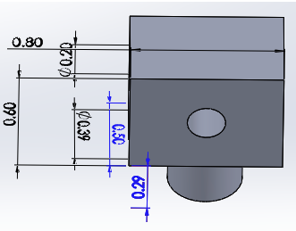
In order to secure the Arduino Mega, I modeled the screw holes position off of the Arduino Mega datasheet. In SolidWorks, I modeled the Head Top Cover by drawing centerlines and by using the Smart Dimension feature.

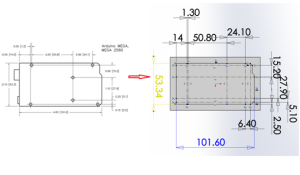
Figure 1: Screw Hole Position

Next, I determined the screw hole diameter and depth.

According to the Arduino datasheet, “all Arduino mounting holes are 3.2mm in diameter. They will accommodate M3-0.5”; I decided to use the M3- 0.5 screw for the Arduino Mega on the Head Top Cover.

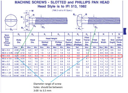
Below, I provided information on the M3-0.5 screw type.

Source: http://www.spaenaur.com/pdf/sectionR/R11.pdf

Figure 2: M3-0.5 Screw

The datasheet says the diameter of the screw hole should be in the range of 3 (Ds) to 3.5mm (DA); I chose 3.02mm diameter for the screw holes in the Head Top Cover.

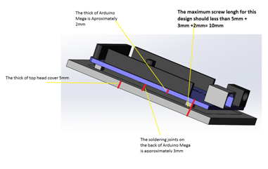
To determined the depths of the screw holes, I adding the width Top Head Cover and the Arduino Mega.

Figure 3: Screw Hole Depth

The best screw that is available for my design is the M3-0.5 with a length of 8mm.

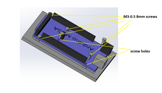
The equation I used  to determine screw hole depth is (screw hole depth on the Top Cover) = (screw length) – (the width of Arduino Mega) => 6mm = 8mm – 2mm.

Figure 4: Finished Head Cover


Head Back Cover Design

I made two holes on the Head Back Cover of RoFi’s head for the power and USB port.

I used the reference dimention feature
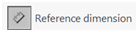
Smart Dimension feature in SolidWorks to show the dimensions of the holes.

Note: Because we are working in 3D, to measure the distance of two lines, I made sure the two lines were placed in parallel and in the same plane.  In the figure below, I added two centerlines as the two reference lines which are parallel and in the same plane which relates to the power and USB cord.

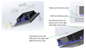
Figure 5: Power and USB Port Hole

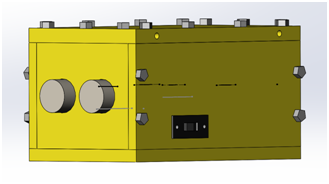
To make it easier for me to determine the size of the back cover, I included the ultrasonic sensor.

Figure 6: Visualize Dimensions

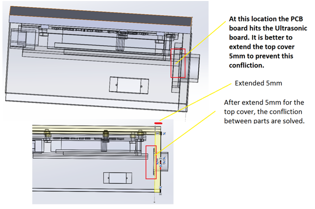
I strategically placed the ultrasonic sensor and the Arduino Mega so that they fit comfortably in RoFi’s head. The thickness of the ultrasonic sensor is approximately 2mm and could easily hide in the head front cover; therefore the space for ultrasonic sensor is not necessary 22mm. In this design, I made the size for the Head Front Cover to be 59.34x51mm.

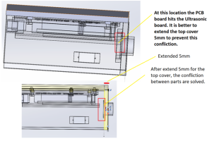
Figure 7: Assembly Analysis

Power Switch Design

Below is the design for the power switch and the location of the switch relative to RoFi’s head.

image8

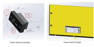
Figure 8: Power Switch

image9

Figure 9: Power Switch Location

RoFi’s Hat Design

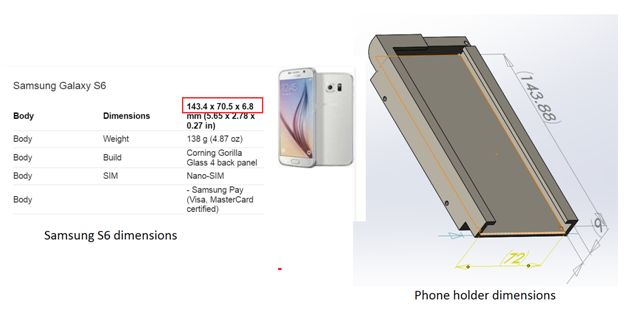
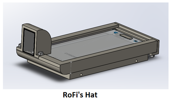
RoFi’s hat is used to hold the Android phone and is larger than RoFi’s head. The advantage of RoFi’s hat is that it allows the designer to only redesign the hat to fit a new phone without having to redesign the whole head.

image10

Figure 10: RoFi’s Hat

In Figure 10 you’ll notice that I designed the hat to be larger than the phone because I want to avoid friction that might scratch the phone.

Periscope Holder Design

Figure 11 indicates the position of the camera relative to the hat.

image11

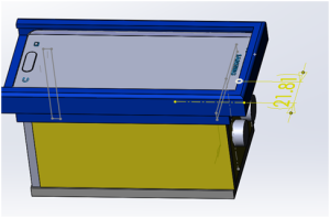
Figure 11: Camera Location

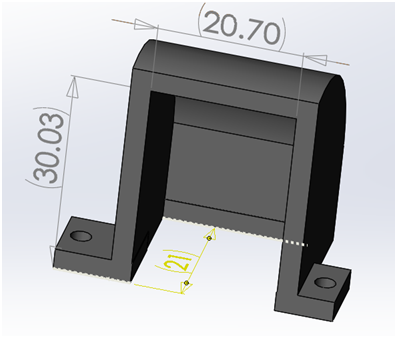
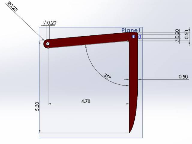
Figure 12 shows the dimensions of the periscope.

image12

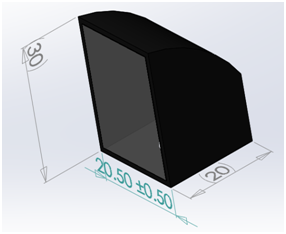
Figure 12: Periscope Dimensions

Figure 13 is the periscope holder that encases the periscope.

image13

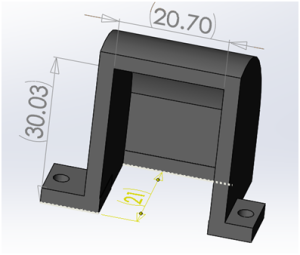
Figure 13: Periscope Holder

Finally, I placed the periscope in a location that allows for proper viewing.

Figure 14 shows RoFi’ hat including the periscope holder.
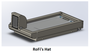
image14

Figure 14: Hat

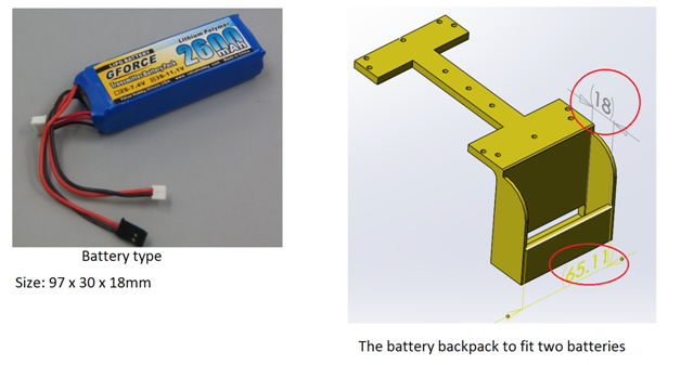
Battery backpack design

I used the same techniques for designing the periscope to design the battery backpack and body riser.

image15

Figure 15: Battery Backpack and Body Riser

Head Overview

Figure 15 shows the final product of RoFi’ head containing all the components.

image16

Figure 16: Head Overview

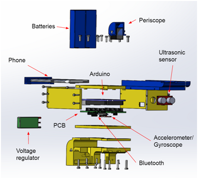
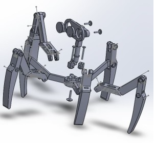
Figure 17 shows the exploded head view with all the components.

image17

Figure 17: Exploded Head View

Leg Design

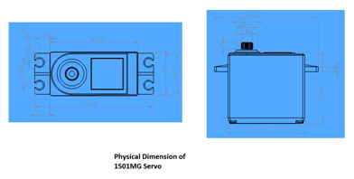
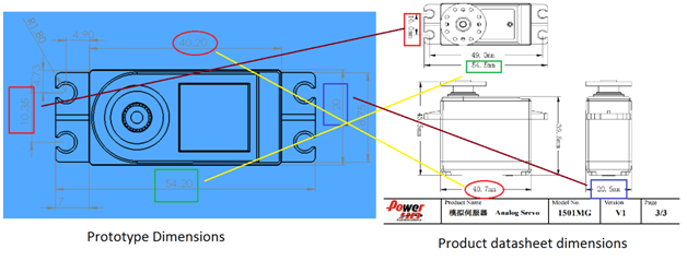
To design RoFi’s legs I imported the 1501MG servo into SolidWorks from the manufactures website. I found there was a prototype of the 1501MG servo on grabcad.com which is available for download. I downloaded the servo and took measurements in SolidWorks and compared it with the measurement of the datasheet.

1501MG servo prototype measurements in SolidWorks:

image18

Figure 18: 1501MG SolidWork Dimensions

image19

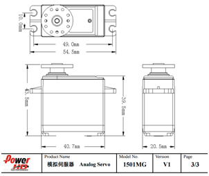
Figure 19: Datasheet Dimensions

Figure 20 compares the prototype dimensions with the product datasheet dimensions.

image20

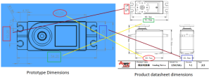
Figure 20: Servo Dimension Comparison

Figure 20 indicates there is a 0.3 – 0.5mm difference between the product datasheet and the prototype. I chose to use the product datasheet dimensions because it is slightly larger and can accommodate the smaller servos if needed.

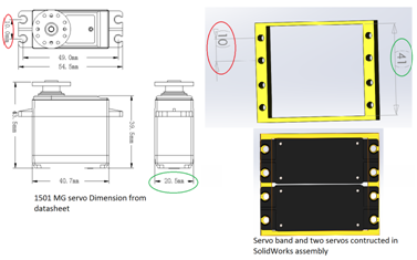
Figure 21 shows the servo band which secures the servos in place.

image21

Figure 21: Servo Band

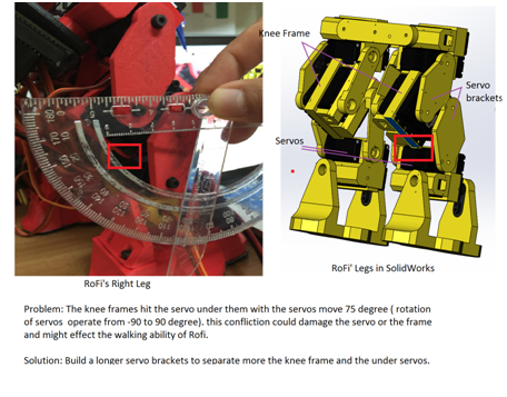
I used a protractor and ruler to measure the printed parts, and I corrected any flaws in my SolidWorks model.

image22

Figure 22: Knee Measurement

image23

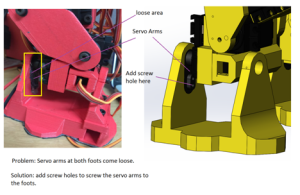
Figure 23: Corrected Loose Servo Arm

Foot design

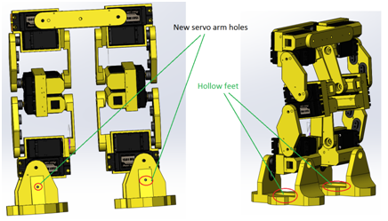
To minimize the mass of RoFi’s feet, I made holes in the bottom of the feet. Figure 24 shows the final product of the new foot design.
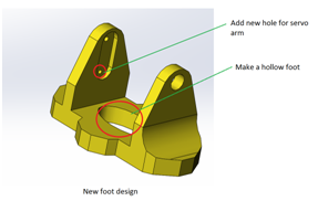
image24

Figure 24: Foot

Leg Overview

Figure 25 shows the complete view of RoFi’s legs with new feet.

image25

Figure 25: Legs

Leg diagram

Figure 26 shows the leg diagram.

image26

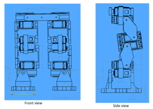
Figure 26: Leg Diagram

Completed Design

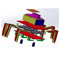
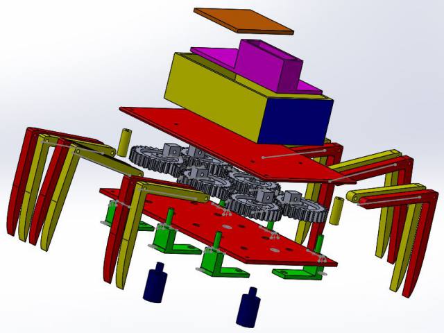
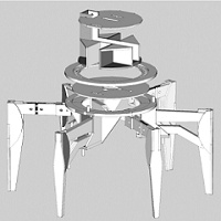
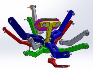
Figure 27 shows the completed design of RoFi.

image27

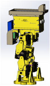
Figure 27: Completed Design

Sources for part dimension verification:

Atmega ADK: https://www.arduino.cc/en/Main/ArduinoBoardMegaADK

Samsung s6: http://www.gsmarena.com/samsung_galaxy_s6-6849.php

Batteries: http://www.valuehobby.com/gforce-2600mah-tx.html

Servo 1501mg prototype downloads from:

https://grabcad.com/library/power-hd-1501mg-rc-servo-1

Spring 2016: 3DoT David Board Troubleshooting

BY: Christopher Hirunthanakorn (Missions, Systems and Test Engineer)

Introduction:

After receiving the assembled 3DoT board that my project manager (Omar) and manufacturing engineer (Andrew) put together, tests were performed to make sure the board was functional. The basic firmware was uploaded by the assembly team, so that step was skipped. More information for uploading firmware to the 3DoT board can be found in Tae’s post for the 3DoT Goliath.

Related Requirements:

  • The 3DoT David shall be a robot that demonstrates the capability of the new 3DoT micro-controller for DIY hobbyists.\

3DoT David Board Troubleshooting

There were four tests to check the functionality of the 3DoT board, which are listed below.

  1. 3DoT board can be turned on and off by using the switch.
  2. Arxterra App can connect to the 3DoT board via bluetooth.
  3. Two motors can be controlled by the 3DoT board.
  4. The battery can be recharged when a micro usb cable is connected as indicated by the LED.

After performing all of the tests, it was found that there was an issue with the motors. When a motor was connected to the motor A connection, it would operate normally. However, that same motor would not work for the motor B connection even though the code was driving both motor connections at the same speed.. It should be noted that this issue was also found on the 3DoT board that the 3DoT Goliath assembled.

image

In order to address this issue, Tae, Nick, and I met up to troubleshoot the problem. The following code in order to test both motor connections at the same time.
code

The following test procedure was used to find the source of the problem.

Test Procedure:

  1. Take out the battery before testing using a multimeter
  2. Set the multimeter to measure resistance setting in the 100k ohm range
    1. Check for shorts on the TB6612FNG Dual Motor Driver Chip
    2. The measured impedance of any two pins should be much higher than the 100k ohm.
    3. If a value of 0 resistance or close is displayed, then there is a short.
  3. Plug the battery back in and turn on the 3DoT board.
  4. Measure the voltage across the motor terminals to make sure the correct voltages are outputted.
  5. Measure the voltage across the Atmega 32u4 pins that are connected to the TB6612FNG Dual Motor Driver Chip to make sure the correct voltages are outputted. Those pins are PB5, PB6, PC6, PD7, PF5, PF6, and PF7.
  6. Record results

The results of our test are as follows:

  1. There were no shorts on the TB6612FNG Dual Motor Driver Chip.
  2. We measured the expected 5 Volts at the motor A connection but no voltage was detected at the motor B connection.
  3. We measured 3.3 Volts for the motor A connections from the Atmega 32u4 pins but we measured 2.67 Volts for the motor B connections. We were unable to find out what was causing the motor B connections to have a different voltage than the expected 3.3 Volts.

Nick tried unsoldering and resoldering the dual motor driver chip but that had no effect on this problem. He told us that the possible causes of this issue could have been from the shipment of the parts, electrostatic discharge, heat, during assembly, etc. Because no solution was found, we informed Professor Hill about this issue and returned the 3DoT boards to be analyzed and repaired. We are currently using a Sparkfun Pro Micro as a replacement for demonstrations and testing.

Conclusion:

This experience showed the importance of testing all components that are purchased or received to make sure they are functioning properly. It also highlighted the importance of troubleshooting and establishing a procedure for testing and recording results.

Update: The 3DoT Board has been fixed and is fully functional.

Sources:

  1. Spring 2016: 3DoT Firmware upload to 3DoT Board

Spring 2016: 3DoT David Simulation and New Design Parts

BY: Andrew Saprid ( Manufacturing Engineer)

Introduction:

Since the first prototype made in solidworks was difficult to 3D print, the parts had to be redesigned. They have to be as flat as possible to make it easier for the 3D print the parts.

Related requirements:

Level 2 system requirement follows:

  • The 3DoT Spider shall incorporate 3D printed parts for the legs, body, or head. This follows from the level 1 requirement dictating the limit on 3D printing times.

Table of Contents

3DoT David Model exploded view and simulation

Exploded View

David_exploded_view1Simulation

A simulation is shown to clearly define the movement system in different views: 

Full view NewdesignFullview Corner viewNewDesignSideView

Top viewNewDesignTopView

New Design Parts

Chassis

The new design is made in solidworks.These are the top and bottom plates. The top and bottom plate will be assembled together as a chassis for 3Dot David Spider. The dimensions for these plates are 12 centimeters in length and 7 centimeters in width with an extrusion of 0.2 centimeters for each plate. For the bottom plate, holes are 0.39 centimeters. They are made to fit the gears as they rotate on the surface of the plate. Small holes, dimensioned at 0.2 centimeters in diameter,  on each plate connect them together. For the top plate, 0.2 centimeters holes are made in the middle to connect the PCB box on top of the plate.

Chasis

Gears

Gears are bought in Amazon.The large gear has 30 teeth, and measures to be 3 cm. The small gear has 10 teeth, and measures to be 1 cm. 6 large gears and 4 small gears will be used to make the gear train. Calculations are done to obtain the gear ratio.

Refer to Gear train blog post for details (Spring 2016: 3DoT David Gear Train)

GearsLegs

Femur and the tibia are combined as one leg part. The length of the femur is 4.78 centimeters. The length of the tibia is 5.3 centimeters. The hole on the femur is 0.25 centimeters in diameter. The hole will connect the joint as shown on the right. Two legs will have the same dimensions as it connects to joint. The space between the two legs will have 0.5 centimeter cushion.

Leg_study1     gearmotion2

Joint

The joint measures to be 0.8 centimeters in length and 0.6 centimeters in width with an extrusion of 0.5 centimeters. The hole in the box is 0.20 centimeters. The cylinder connected to the box is 0.29 centimeters in length with a diameter of 0.39 centimeters.

Screen Shot 2016-04-11 at 12.06.02 PM

Plank, Solidworks modeled gear, and leg studies

This part is called the plank that will be attached to the bottom of the bottom plate. The reason for the plank is to make the leg, connected to the gear,  lift up in an angle as the gear rotates in a full 360 degree rotation. In the 3 centimeter gear, the radius 0.76 centimeters. The gear is modeled to simulate the gear train in Solidworks.

Refer to leg study blog post for calculations ( Spring 2016: 3DoT David Leg Movement Angle Study)

Plank       Screen Shot 2016-04-11 at 12.08.41 PM


In the middle gear of the gear train, the leg is lifted because of the plank. The lift is about 13.30 degrees according to the leg study. This is the position that it will start for the middle gear.

gearmotion

The position that the corner gear of the gear train will start at is 5 degrees as the leg rests on top of the plank, where the cylinder stops the leg from going anywhere else.

gearmotion2


Gear view

A better view is shown from the top as it shows the gear train and the position of all the legs. 12 legs will be used, and 2 legs will act as one part with the same dimensions.


Gear_view

Conclusion:

The previous design was difficult and complex to build similar to the Hexbug Spider. The new design is made to simplify the CAM Movement system of the HexBug Spider, which will be applied to the legs connected to the gears, as the two motors (located on the bottom plate) will rotate both sides of the gears in a full 360 degree rotation. The two motors will attach to the 1 cm small gears.


Spring 2016: 3DoT Spider-Bot Mechanism Research

BY: Omar Mouline ( Project Manager)

Introduction

The 3Dot David project mechanical requirement was to build a small size spider bot that can walk using two motors. When the project was assigned to us, We were given The hex bug 1 in the picture below  as a prototype. Screen Shot 2016-04-09 at 2.15.27 PM

Related requirements

  1. The 3DoT David shall be a low cost project with a total cost that does not exceed $79.95, which includes the cost for manufacturing, PCB, battery, and other components.

Table of Contents

Research different mechanisms of spider bots

After conducting some research on other types of mechanisms, the first design that attracted my attention was a toy named  “Combat Creature”. The Combat Creature is a discontinued toy that i believed was cooler that the hex bug to build.

Combat creature

Screen Shot 2016-04-09 at 3.25.07 PM 
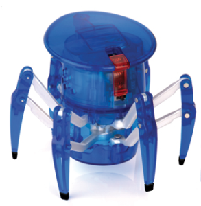
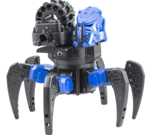
A 3 part video Youtube video of disassembling the toy was found explaining the mechanism and showing the different parts of the robot: Part 1Part 2, and Part 3.

Jerry Mantzel mechanism

Screen Shot 2016-04-09 at 3.29.37 PM

Jerry Mantzel project was to build a Giant Version  of the Combat Creature. Inspired by the combat creature, he adjusted the design of the toy to make a Rapid Prototype as shown in Video.  Adjustments were made To have an easy prototype to 3D print as shown in this  Video.

Hex Bug 1 Mechanism

Screen Shot 2016-04-09 at 3.57.35 PM

This prototype is the design that was assigned for our project. The picture on top show the exploded view of the cam based mechanism of the spider bot.

Hex Bug 2 Mechanism

11oych Gear_view Side_view-1

This design is the new design we are using for our project. It is less complex, gave us less printing time, All the parts can be 3d printed, and reduce the cost of manufacturing.

Joe Clan Mechanism

steamspiderOn this design the Spider Bot move side ways. I found a lot of information in this Page. The Professor provided me with more links for this model:

Two motors controlled transparent Joe Clan

Leg Movement Mechanism

Phone Controlled based Mechanical Joe Clan Spider

Legs movement

Theo Jansen Mechanism

Strandbeest--Full-Walking-AnimationStrandbeest-Walking-Animation

Links That explain more the mechanism of this Spider Bot:

Details on Theo Jansen mechanism

Adam Savage’s One Day Builds

A Theo Jansen´s mechanism

Theo Jansen style robot leg

Walking machine in the middle of construction

Baling Wire Walker

Conclusion

After looking on all of these design, we started working on the Hex Bug mechanism 1 and on process of designing it on solid works we quickly started running to problems. Trying to solve all the problems the main issue we had is the 3D printing quality for the small joints and some other parts. for that small design we needed precision in order to get the result we want specially for an important part like the joint. We then decided in the tenth week as a team too change the design to the Hex bug mechanism 2 which is less complex. Gladly, we were able to make and achieve all the requirements.


Spring 2016: 3DoT David Printing Time

BY: Andrew Saprid ( Manufacturing Engineer)

Introduction:

Calculations were done by adding the quantity to the table and adding the total amount of printing time for each part. The calculations for all the parts are then added and highlighted on each of the three tables for the total print time of all the parts.

Related requirements:

  • As part of our level 2 requirements, 3D printing time shall not exceed the 6 hour limit. Each part will not exceed the 2 hour limit of printing. Three tables are shown in the figure below to compare scenarios, if all the parts are to be 3D printed.

All parts printed

If the parts are all printed, it takes 7.78 hours, which exceeds the 6 hour limit of printing.

12 legs to be printed takes 132 minutes to print. Each leg to print takes 11 minutes.

4 connectors takes 8 minutes. Each connector to print takes 2 minutes.

6 joints to be printed takes 6 minutes. Each joint to print is 2 minutes.

6 planks to be printed takes 8 minutes

Each part did not exceed the 2 hour limit print time.

exceedlimitBottom plate and Top plate excluded

By excluding the top and bottom plates to be laser cutted, it takes about 4.49 hours, which goes below the 6 hour limit of printing.
hr4.49Excluding the PCB box and cover

By excluding the PCB box and PCB box cover, it takes about 5.5 hours, which also goes below the 6 hour limit of printing. The PCB Box and the cover makes the PCB invisible to the eye, which does not affect the level 1 requirements, and saves printing time.

hr5.5Conclusion
The best results are excluding the top and bottom plate to be laser cutted, or excluding the PCB box and PCB box cover. The best scenario would be to exclude the PCB box a
nd cover. The rest of the parts will be 3D printed, which takes about 5.5 hours.

Sources:

Thanks to Min, the manufacturing engineer from the Velociraptor Team for printing all the parts, the results are in for the 3D printing time.

Spring 2016: 3DoT Spider-Bot Cam Simulation

BY: Andrew Saprid ( manufacturing engineer)

Introduction

The initial design assumed that the CAM movement system would be used. Therefore, research on the CAM system and this CAM simulation were performed.

Requirements

Level 2 system requirement states:

  • The 3DoT David shall use two micro motors for the movement system of the robot.

Table of Contents

CAM movement system model

All parts are assembled and connected with the top base and bottom base. The difficulties of making the CAM simulation included many mating in assembly that crashed the solidworks software many times. To prevent the solidworks software from crashing, mates may have to be suppressed so that resources may not be used as much in the software. A lot of parts will be 3d printed, and may exceed the 6 hour limit.

fullview

Here is the CAM and follower simulation of the 3Dot David model. By moving the CAM connected to the follower, three legs will move up, while the other three legs will move down:

CAM

Looking closely to simulate of the CAM movements system of the Hexbug Spider, steps are broken down to analyze and observe each part. The follower (yellow) is connected to the CAM (orange). By moving the follower, it will rotate just as the CAM rotates. The top femur (blue) is connected to the bottom femur (green).  It’s support (red) will be connected to the bottom base. The bottom femur support (gray) will be connected to the top base.

CAM_SimulationBLog
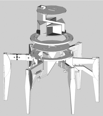
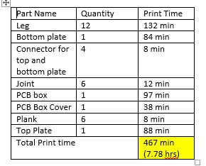
Hex bug design parts

Follower, CAM, and CAM cover

The follower (yellow) is connected to the CAM (orange). The CAM cover (purple) holds the CAM and follower in place.

CAM_Follower

Top femur

Top femur (blue) is connected to the joint(gray).

topview

Joint

Joint (gray) is then connected to the bottom femur (green). This will make the joint free to rotate, and the top femur (blue) to go up and down.

joint

Tibia

The tibias (gray) are then connected to the femurs.CAM_SimulationBLog1

Bottom Femur Support and Top Base

The bottom femur support (gray) is the connected to the top base (yellow).

Screen Shot 2016-04-11 at 10.36.29 AM

Bottom Femur Support and Top Base

The bottom femur support (gray) is the connected to the top base (yellow).

Screen Shot 2016-04-11 at 10.38.03 AM

Slot bolt and the slot hole on the top femur

The slot bolt (gray) will restrict the top femur (blue) from going out. When moving the follower, the top femur will move, dependent on the slot hole.

slotconnection slothole

Conclusion: CAM movement system model

All parts are assembled and connected with the top base and bottom base. The difficulties of making the CAM simulation, it included many mating in assembly that crashed the solidworks software many times. To prevent the solidworks software from crashing, mates may have to be suppressed so that resources may not be used as much in the software. A lot of parts will be 3d printed, and may exceed the 6 hour limit.

Spring 2016: 3DoT David Gear Train

BY: Andrew Saprid ( manufacturing engineer)

Introduction:

The mechanical system for the 3Dot David is the gear train. Gears have teeth, which are designed to make the gear train rotate 360 degrees possible. The motor will operate around 5 volts, and it will be connected to the small gear as it drives the large gear. With the gear train setup, the 3Dot David will be able to move across the lyceum floor.

Related requirements

Level 2 system requirement follows:

  • The 3DoT David shall use two micro motors for the movement system of the robot.


Motor calculations:

The motor previously used at 50,000 RPM was not the right value because it was unrealistic for the spider to run at that pace, which could easily break components inside of it. In order for the legs to move at a slow steady pace, the motor using will give 360 RPM at 5 volts as the legs will run at a pace of 2 cycles per second.

The team will use the motor at 360 RPM to drive the small to large gears.
120 RPM / 60 sec = 2 cycles per second for the large gear The gear train is 120 RPM


gear_ratio_updated3

Conclusion

The team will use the motor at 360 RPM to drive the small to large gears.

120 RPM / 60 sec = 2 cycles per second for the large gear

Source:

http://www.engr.ncsu.edu/mes/media/pdf/gears

Spring 2016: 3DoT David Leg Movement Angle Study

BY: Andrew Saprid ( manufacturing engineer)

Introduction:

The leg must be lifted in order for the spider to walk. Supplying 5 volts will be efficient enough to lift the leg, and rotating 360 degrees continuously.

Related Requirements:

Level 2 system requirement states:

The 3DoT David shall use two micro motors for the movement system of the robot.

Leg Study

Calculations are done to find out the angle and the leg lifted off the ground. The calculated  circumference of the 3 cm gear came up to be 4.78 cm. The initial lift of the leg is to be 5 degrees. by using sine to find x, it came to be .42 cm. The final lift is 13.3 degrees. The same method is done which came to be 1.1cm. Subtracting .42cm to 1.1cm, came up to be 0.68 cm off the ground.


           Initial lift: 5 degrees                                                            Final Lift: 13.30 degrees

Screen Shot 2016-04-10 at 3.30.39 PMScreen Shot 2016-04-10 at 3.31.50 PM


The calculations are as follow:

Circumference of the 3 cm gear

C = 2πr  = 2π(0.76) = 4.78 cm

Given 5 degrees for the initial lift

sin(5) = x/4.78

4.78 x sin(5) = .42 cm  

Final lift is 13.30 deg

4.78 x sin(13.30) = 1.1cm

1.1cm – .42cm

= 0.68 cm off the ground