FALL 2015 MicroBiPed Preliminary Design Documentation
MISSION OBJECTIVE
Fall 2015 MicroBiPed (μBiPed) is inspired by the BiPed designed by Jonathan Dowdall of Project BiPed. The objective for this year’s project is to use the BiPed & μBiPed designs to prototype a toy robot that resembles a Velociraptor. To push the objective towards prototyping a toy requires a large emphasis on cost. Although the mission is yet to be determined, the μBiPed must be controlled and be able to communicate with the Arxterra™ Android application.
REQUIREMENTS & VERIFICATION
Level 1 – Program Requirements
- According to the CSULB Fall 2014 Academic Calendar, the μBiPed robot shall be tested by December 10, 2015; the date of the last day of 400 D.
- According to 2014-2015 ARXTERRA µBiPed’s parts list, the project shall cost no more than $400.00.
- Verification:
http://arxterra.com/final-documentation-microbiped/
- Verification:
- To push the objective of the μBiPed towards the remote control toy industry, the lifetime & playtime shall be constrained to the mental development of a child 7-12 years old.
- Verification:
https://www.cpsc.gov//PageFiles/113962/adg.pdf
- Verification:
Level 1 – Project Requirements
- In accordance with the project name, the μBiPed shall travel on 2 legs.
- Verification:
https://en.wikipedia.org/wiki/Bipedalism#Bipedal_robots
- Verification:
- To be considered a miniaturized BiPed robot, the μBiPed shall range between 0.6 (120mm) ± 10% of Rofi’s dimensions according to the ratio of an MG92B μservo to Rofi’s servo.
- In accordance with the obstacle course, the μBiPed shall walk up an incline that starts initially at 8° and then decreases to a 6° slope in relation to level ground.
- In accordance with the obstacle course, the μBiPed must walk over or on an object at about a 45° angle and a height of 2 cm.
- Verification:
The μBiPed will walk over an object of about 2cm ± 1cm. The 1 cm is for margin of error. This will be measured by a ruler.
- Verification:
- In accordance with the obstacle course, the μBiPed shall walk on surfaces of varying friction coefficients:
- Carpet: 1.0 static [1]
Verification:
http://www.sciencedirect.com/science/article/pii/S187770581000367X - Linoleum: 0.5 static [2]
Verification:
http://www.sciencedirect.com/science/article/pii/S187770581000367X - Rubber: 1.0 static [3]
Verification:
http://www.sciencedirect.com/science/article/pii/S187770581000367X
- Carpet: 1.0 static [1]
- In accordance with customer specifications, the μBiPed shall communicate on Bluetooth -to an Android phone app.
Verification:
https://www.arxterra.com/final-documentation-microbiped/ - In accordance with customer specifications, the μBiPed shall have a payload that outputs a toy-like behavior.
- Verification:
The current proposal for a payload is to use a cheap sensor that can react to certain changes in the environment.
- Verification:
- To follow toy safety regulations, the μBiPed shall comply with the federal toy safety standard, ASTM F963-11.
Verification:
http://www.cpsc.gov/en/Business–Manufacturing/Business-Education/Toy-Safety
For information on how these requirements will be verified, please see the Level 1 Requirements post.
Level 2 – System Requirements
- According to CSULB 2015 Fall Finals Schedule, all subsystems shall stay within the time phasing to complete project μBiPed (by the due date of 12/10/15) and thus meet Level 1, requirement 1.
- Verification:
The current task in the project schedule is planning. Along with the remaining tasks, (manufacturing, software integration, testing, and project video) the schedule will determine the allotted time for each phase of the project.
- Verification:
- To have a realizable budget, the chassis shall be manufactured directly at CSULB and thus meet Level 1, requirement 2.
- Verification:
3D printers and CNC machines are available at the behest of their respective departments.
- Verification:
- To create a toy built for the attention span of a child between the ages of 7-12 years old, the μBiPed shall last 7-15 minutes and meet Level 1 requirement 3.
- Verification:
To incorporate the mission objective of building a toy, the 4 AA batteries must be able to maintain system operations regarding the loads of chassis and 6 servos.
- Verification:
- To facilitate all the algorithmic functions of a walking BiPed, the Arduino MICRO with an ATmega 32u4 Microcontroller will be used to meet Level 1, requirement 4.
- Verification:
With the reduced amount of servos, the amount of PWM pins required are also reduced. Therefore the Arduino MICRO is the better choice in comparison to the Arduino UNO.
- Verification:
- To maintain balance (while retaining core features of a BiPed), installment of a head & tail will be incorporated to the chassis to adjust the center of balance and thus meet Level 1, requirement 4.
- Verification:
The reduced freedom of movement also means less ways to balance while moving. To compensate, alternative appendages can be attached to maintain the center of balance while moving.
- Verification:
- To reduce the dimensions of the BiPed, the μBiPed shall use a two-servo to one-leg system to eliminate bulkiness and meet Level 1, requirement 5.
- Verification:
The previous semesters utilized 6 servos per leg to increase the articulation, but increased the bulk, weight, and the height. A more mechanical approach will be used to control the legs to imitate a velociraptor model.
- Verification:
- For the μBiPed to detect and adapt to inclines, a gyroscope shall be used to preserve chassis balance and meet Level 1, requirements 6 & 7.
- Verification:
Level 1, requirement 6 & 7 indicates that the BiPed shall move up and down inclines. To adapt to such scenarios, the μBiped must be able to keep the body balanced by adapting to its relative center of gravity.
- Verification:
- In regards to bluetooth communication with the Arxterra app, an IGT-3200 wireless adapter will be used to meet Level 1, requirement 9.
- Verification:
To be controlled by an Android app, the machine must have a wireless adapter to enable wireless communication.
- Verification:
- To adapt to different friction coefficients due to varying surfaces, an interchangeable shoe system will be used should the course terrain be changed..Level 1, requirement 8.
- Verification:
This requirement is for flexibility in case linoleum tiles and carpet are no longer the terrain.
- Verification:
- To produce a toy that complies with remote control safety regulations, the μBiped must be designed for the ages of 7-12 years old and thus meets Level 1, requirement 11.
- Verification:
To create a remote controlled toy, the μBiPed must comply with US Consumer Product Safety Commission for age determination guidelines.
- Verification:
- The μBiPed must avoid walls at a distance of (TBD). Determined by the mission profile. The distance may be determined based off of the constraints of the parts used to determine distance, or the customer may indicate distance.
- Verification:
Will have the μBiPed walk towards an object, i.e. a wall, and see if the μBiPed will stop or try and change path. The distance will be measured with a tape measure.
- Verification:
DESIGN INNOVATION
Paul Oo (Project Manager)
Balanced Walking
Due to previous BiPeds using higher amount of servos for better articulation, the project has shifted towards having large legs/feet and heavy/bulky design. This year’s μBiPed design will be pushed towards prototyping a toy (specifically TITRUS III). This objective shall be the reference for system and subsystem designs.
Step 1. Brainstorm
- Finalized Balancing Attributes:
- Type of Legs – Velociraptor (reverse joint)
- Head – Purely payload (sensor)
- Tail – Oppose head movement
- Feet – Multipurpose (shoes)
Step 2. Lateral Thinking
- Finalized Forced Relationship:
- Rubberband – Head and tail in opposing directions
- Top – Gyro detects chassis orientation
Step 3. Solution
- Design Conclusion
To produce a toy-like design, the listed attributes must remain simple. By considering the design innovations of TITRUS III, the μBiPed will base its attributes on the concept of minimalism. Furthermore, the addition of shoes (for different terrains) will give customers incentive to invest into the product’s future developments.
ELECTRONIC SYSTEM DESIGN
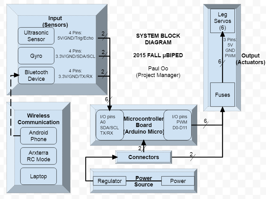
System Block Diagram:
This block diagram explains the system architecture of the μBiPed in regards to its connections. The μBiPed can be broken down into three main subsystems: inputs, outputs, and microcontroller. The inputs consists of an ultrasonic sensor (HC-SR04™), a gyroscope (TBD), and a bluetooth system (HC-06™). The outputs consists of 6 servo motors (MG92B). Finally, the microcontroller board consists of a battery and the Arduino Micro (ATmega 32u4).
Interface Definitions:
- Ultrasonic Sensor (HC-SR04TM) – LED EYES
- The ultrasonic sensor will connect to 4 pins on the microcontroller for 5V power, ground, triggering, and echoing. It will be used to detect obstacles in the way of the robot and prevent the µBiPed from hitting the object.
- The reason for using an ultrasonic sensor is to possibly add a transducer to the sensor. Addition of the transducer will reduce the ultrasonic frequencies to a level that humans can hear. This audible sound is a toy feature.
- Gyroscope (ITG-3200) – ORIENTATION
- The gyroscope will be attached to the SDA and SCL pins on the microcontroller. It will be used to detect the orientation of the µBiPed to allow the microcontroller to make balance-based corrections.
- The reason for using a gyroscope, rather than an accelerometer, is due to the multiples degrees of movement the legs will have to resemble a hip-based leg.
- Bluetooth Device (HC-06TM) – COMMUNICATION
- This Bluetooth device will be a slave to the microcontroller. It will be attached to the RX and TX pins of the microcontroller. The HC-06TM will be used to communicate to an Android phone and receive commands from the Arxterra™ application.
- The reason for using a bluetooth system is based on customer specifications.
- Microcontroller Board (Arduino Micro – ATmega 32u4) – Control
- The microprocessor must be cost efficient, small, and be able to use Dowdall’s code for the Arduino IDE.
- Requirements of the microprocessor:
- Dynamic memory or SRAM: 4.7 KB
- Flash memory: 14 KB
- Meeting these requirements are imperative for the μBiPed group because the variable initialization does not take up the most dynamic memory (only about 17% of the dynamic memory is used by the global variables). Map() function requires the most dynamic memory.
- Requirements of the microprocessor:
- The microprocessor must be cost efficient, small, and be able to use Dowdall’s code for the Arduino IDE.
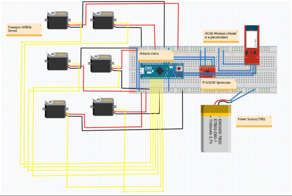
Fritzing Diagram
Michael Balagtas (Manufacturing)
Trade off studies
Railly Mateo (Computer Systems)
Servo comparison
| Servo | Price (1unit) | Torque | Speed | Weight | Dimensions |
| MG90S | $4.35 | 4.8V = 1.8kg/cm6.0V = 2.2kg/cm | 4.8V = 0.10sec/60deg6.0V = 0.08sec/60deg | 13.4 g | 22.8 x 12.2 x 28.5mm |
| MG92B | $7.00 | 4.8V = 3.1kg/cm6.0V = 3.5kg/cm | 4.8V = 0.15sec/60deg6.0V = 0.11sec/60deg | 13.8 g | 22.0 x 12.0 x 31.0mm |
| SG90 | $4.31 | 4.8V = 1.0kg/cm | 4.8V = 0.12sec/60deg | 9.0 g | 22.0 x 11.5 x 22.5mm |
The above chart compares 3 possible servos to use for the µBiPed project. The chart compares torque, speed, weight, rotation, and price.
- Torque is important because if the servos do not have enough torque the µBiPed will not move.
- Heavier servos means larger batteries.
- Slower servos means larger batteries due to a larger operation time to complete the course.
- Speed and weight are important for the sizing of batteries.
- Rotation is needs to 180 degrees to complete the required range of motion.
- Pricing is a desired to lower the cost of the total budget.
After comparing the servos, the group decided on using MG92B for the purpose of having a higher torque rating.
- Although MG90S and SG90 have less weight and lower cost than MG90S, they don’t have as much torque to move the µBiPed.
- The MG92B is also a U.S. products and thus can be delivered much faster than other servos not listed in the chart.
Microcontroller comparison
| Microcontroller | PWM Digital I/O pins | AnalogInputpins | Input Volt. | Dimension | Flash & SRAM | Price |
| Arduino MicroATmega32u4 | 6 | 6 | 7 – 12V | 68.6 x 53.4 mm | 32 kB & 2 kB | $9.00 |
| Arduino UnoATmega328 | 7 | 12 | 7-12V | 48 x 18 mm | 32 kB & 2.5 kB | $25.00 |
The above chart compares 2 possible microcontrollers to use for the µBiPed project. The chart compares pins, input voltage, dimension, memory, and price.
- The amount of pins available for analog and digital I/O’s are important because of the amount of sensors and servos the microcontroller will be connected to.
- We will need to connect 6 servos to analog pins on the microcontroller.
- We will need to connect 2 PWM pins to the payload.
- Input Voltage is used for understanding the amount of voltage the batteries must supply.
- The dimensions are key to creating a transparent embedded system.
- Pricing is desired to lower the cost of the total budget.
After comparing the microcontrollers, the group decided on using the Arduino Micro for the purpose of having a smaller and most cost efficient microcontroller.
- Although MG90S and SG90 have less weight and lower cost than MG90S, they don’t have as much torque to move the µBiPed.
- The MG92B is also a U.S. products and thus can be delivered much faster than other servos not listed in the chart.
Payload comparison – LiDar vs Ultrasonic Sensor – HC
| SENSOR | Sain SmartHC-SR04 | LIDAR-Litev2 |
| POWER SUPPLY | 5V | 6V |
| WORKING CURRENT | 15Ma | 2Ma |
| DIMENSION | 45mm x 20mm x 15mm | 20mm x 48mm x 40mm |
| RESOLUTION | 0.3 cm | 1 cm |
| PRICE | $10.00 | $115.00 |
The above chart compares 2 possible payloads to use for the µBiPed project. The chart compares power supply, working current, dimensions, resolution, and price.
- Determining the amount of power and current needed is important because the microcontroller has a limit of 5V output.
- The dimensions are key to creating a transparent embedded system.
- Resolution is also considered to determine which sensor can provide a better user interface performance.
- Pricing is desired to lower the cost of the total budget.
After comparing the two sensors, the group decided on using the Ultrasonic Sensor for the purpose of having a more cost efficient payload.
- Although Lidar-Lite has better resolution than the HC-SR04, the cost to purchase a single LIDAR overweights its positive trade-offs.
Rapid Prototyping
In order to test the µBiPed, the code from Dr. Dowdall will be uploaded onto an ATmega microcontroller but will be modified to control only six servos. The choice of six servos is to allow for the manipulation of one leg. The purpose is to experiment with leg motion. As the µBiPed is required to step over an object of a certain height, it is important to track the default motion of the leg. This means that if the default movement of the legs does not rise of the 2 cm height a modification to the code will have to be made in order to allow for the ability to walk over an object of 2 cm.
Interface Matrix
Brian Walton (Control & Image Processing)
Task Assignments
Michael Balagtas (Manufacturing)
Michael Nico Balagtas
- Construct physical models of the μBiPed for fast prototyping and error analysis.
- Computer Aided Design(CAD)
- Mechanical- Use Solidworks or DesignSpark to draft preliminary designs for critical review.
- Electronic – Use EAGLE software to draft final PCB design for fabrication through a third party
- Acquire information on how to use CSULB CNC machines or 3D printers for either metal or plastic builds.
- Manufacture parts for final mechanical product using either metal or plastic materials.
- Assemble final product through soldering and occasional post processing.
Railey Mateo
- Will learn C++ programming language to code algorithms using the Arduino IDE.
- Will work with Controls division member to optimize servos and gyroscopes.
- Will browse through datasheets of equipment to locate the appropriate registers of the peripheral equipment.
- Learn how to use IGT-3200 Wireless adapter.
- Algorithms
- Modify frame capture code from Mr. Dowdall to accompany a new two servo design.
- Create state diagrams for the walking frames and the transitions from each frame to the next.
- Code complex algorithms to determine behavior of μBiPed when on or approaching inclined surfaces.
- Code algorithms to calibrate and read input from gyroscopes using I2C communications.
- Develop code to process incoming images from LiDar sensor to make μBiPed respond according to specifications.
Brian Walton
- Servos
- Conduct mechanical stress tests to specify the maximum torque allowed by servos.
- Conduct tests to determine the appropriate PWM signal to acquire proper servo rotations.
- Gyroscope
- Will test gyros for tolerance values and resolution to develop mathematical formulas for the equations
- Will test for any changes to the chip
- LiDar
- Will test and research LiDar sensor to determine optimal operation with algorithms.
- Will develop equations for operation of LiDar system.
- Will work with Computer Systems and Software to optimize servos and gyroscopes.
- Will constantly scrutinize design for noise or power issues.