3D Model!
By Mason Nguyen, Project Manager
Solid Works simulation by Vinh Kim
Solid works model:
In order to build a durable and low budget hexapod, resin molding would the primary component for our team to use. The robot is developed based on a previous version which is focused on the straight-line walking. To enhance its ability to adapt to the terrain, each leg has three revolute joints driven by Power HD 1501 servos. Wasting no time, Vinh Kim our manufacturer started working hard on 3D initial design for our hexapod in Solid Works. Our main priority we would focus on would be the hexapod shoulders. Both robots had the same dilemma where their legs bent forward while walking and ended up tumbling due to an enormous amount strain from the heavy body weight.
To correct that error, we will be limiting the amount of materials that going to be placed on the hexapod. Also, aluminum brackets will serve as a strong supporting pillar on the hexapod shoulders when operating.
Over the weekend, Vinh has been busy working on the Hexapod body design. Full 3D body assemble will be posting up later around the middle of this week.
3D Body:
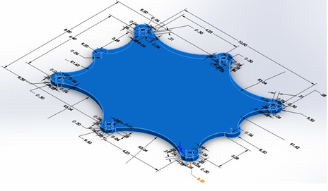
Height and Width = 11 by 9.8
6 large holes is .30 in
26 small holes each .06 in
Femur:
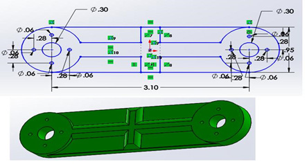
Width = 4.05 in
Thickest = .276 in
Height = .95 in
2 large holes is .30 in
8 small holes each .06 in
Tibia:
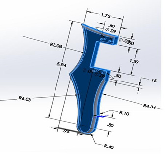
Height = 6.34 in
Width = 1.75 in
Thickest = .354 in
4 small holes each .06 in
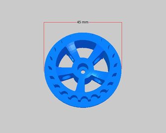
Bracket:
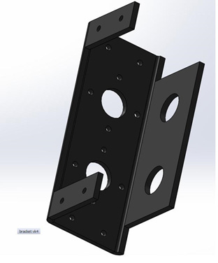
Height = 33 mm
Width = 54.18 mm
16 small holes each .06 in
Aluminum bracket to support the hexapod shoulders
This week goal is to assemble our 3D model!
Vinh Kim is working hard to create and assemble a perfect 3D model. We will have it by the end of this week.
Meanwhile, Chau To our computer programmer continues working hard to program our servos with the edition of the Adafruit driver.
Tien Dang who is our communication engineer also lends the team a hand by assisting Chau with the programming and putting together our hexapod prototype.
Here is a video of our hexapod prototype where we demonstrating how the servos will rotate and operate.