Spring 2018: Micro FOBO Mechanical Designs
By: Miguel Gonzalez (Project Manager & Manufacturing)
Approved by: Miguel Garcia (Quality Assurance)
Table of Contents
Notice
In this blog post, you will learn about initial mechanical designs for the Micro FOBO. We will discuss our thought process for each design component and relate it back to the customer’s requirements. Note that this the first post for the mechanical drawings of the miniaturized FOBO design created by Jonathan Dowdall. New advances in construction and design of the robot will be updated in a future post and linked at the bottom of this page. It is important to note the models shown in this post have yet to be physically tested. But plans to 3D print them have been made and the parts will be tested together. All results will be posted in a follow-up update blog post detailing our results of the models introduced here.
Introduction
The ROFI and FOBO bipeds can be considered as aging robots in which the designs have been used in many occasion for EE 400D projects. This can be particularly helpful if new students like ourselves would like to make such robots, considering resources for these models are plentiful on Arxterra.com. Unlike previous semesters our biped design will not encapsulate the same model but instead be a miniaturized version of those robots. Our group will particularly focus on the FOBO design by Jonathan Dowdall which is found on projectbiped.com. The miniaturized FOBO will be much smaller than the original approximately 60 percent its size and be controlled via micro servos (SG90S). We hope that in miniaturizing the design we can achieve a more efficient way of making the robot walk, turn, and avoid obstacles; all which are some design criteria for the maze.
Related Requirements
Level One Requirements
L1-3: Micro FOBO will have 2 legs.
L1-4: Micro FOBO will be a toy robot based on the design of the FOBO by Jonathan Dowdall.
L1-11: Micro FOBO shall be 60% or less of the overall size of Jonathan Dowdall’s FOBO
Level Two Requirements
L2-2: Micro FOBO dimensions will need to be small enough to fit in a 4in by 4in box for maze purposes.
L2-14: Micro FOBO shall measure within 4.5” x 3.25” x 7.25”.
Micro FOBO Design
For some clarification and for better understanding our design of the Micro FOBO, I have created a color-coded assembly of the robot with matching titles indicating the names of each component. Below I discuss the design of these components that make up the Micro FOBO.
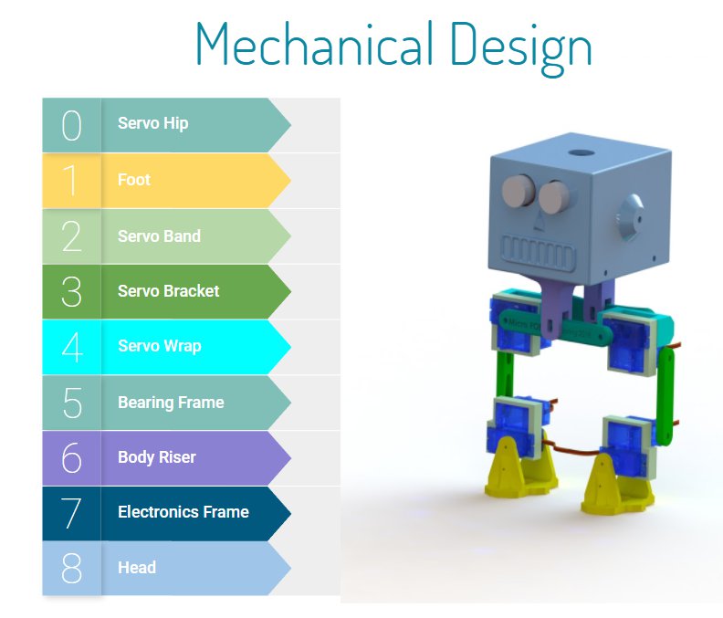
Fig.1 Micro FOBO Colored Parts
As you can see from the image above, the Micro FOBO consist of 9 different parts: Servo Hip, Foot, Servo Band, Servo Bracket, Servo Wrap, Bearing Frame, Body Riser, Electronics Frame, and the Head. Note that Micro FOBO can be made up of multiple copies of the same part component and thus colored coded with the same color. For example, there are four servo bands in Micro FOBO which are shown in light green on the picture. Now that we know which parts make up the robot we can begin looking at the design of each part individually.
Part 0: Servo Hip
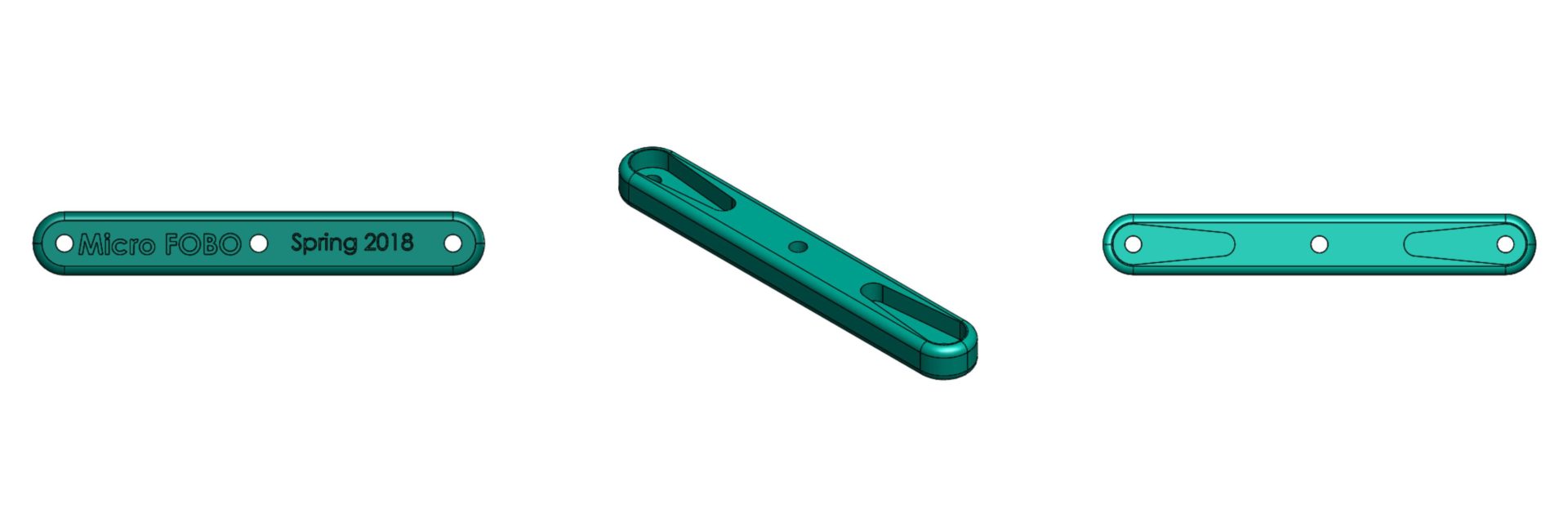
Fig.2 Servo Hip
The “Servo Hip” component of the Micro FOBO is responsible for attaching the two upper micro servos which are the hip servos. This bracket connects both servos (right and left legs) together to act as a hip bone that allows the robot to move its legs left to right. The connection to the servos is made via servo horns that are provided by the manufacturer. This part has two allocated trenches that match the dimensions of the servo horns allowing the servos to mount to the part. The horns are then screwed onto the servo hip using M2.5 screws that are 8mm in length.
Part 1: Foot
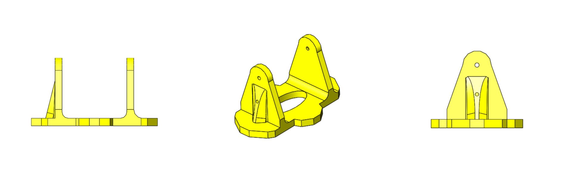
Fig.3 Foot
The “Foot” component is the same for both legs and is a simple shoe like design with wide pads on its sides. The extra material on the sides allows a greater amount of surface to touch the floor allowing the robot to balance easier. Currently, this part is in its simplified state as there is not much detail design put on it. This is because the team plans on mounting UV sensors onto the bottom of the foot where the hole is located. This would allow the sensor to be as close to the ground as possible to maintain an accurate reading. Once we receive the sensor additional design changes will be made to this part. Currently, the part allows the ankle servo, which is the servo closest to the ground, to be mounted onto one side of the foot though servo horn cutouts. The horn cutout is located on the inside wall of the part. The hole then allows an M2.5 X8 screw to secure the servo onto the foot piece.
Part 2: Servo Band
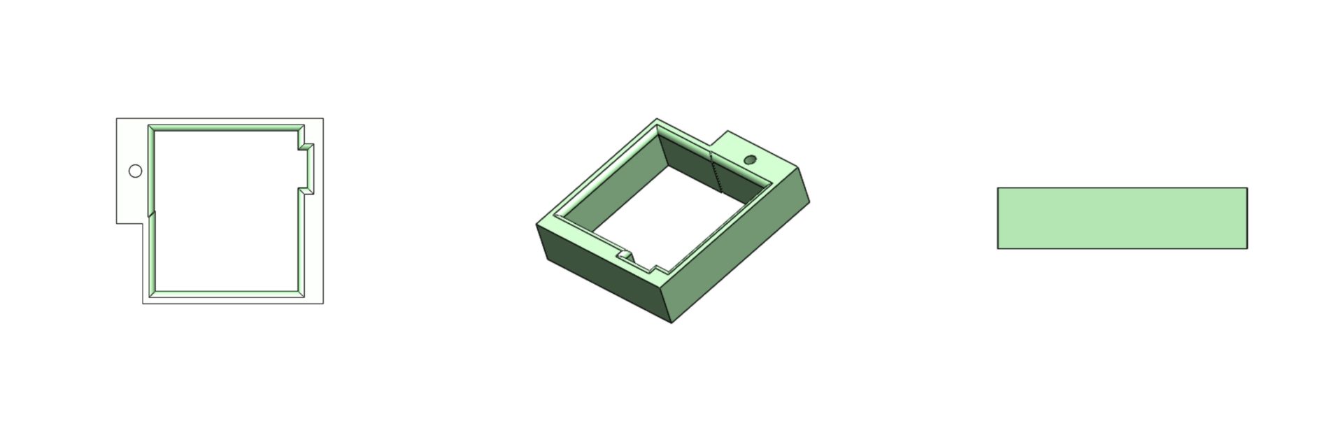
Fig. 4 Servo Band
There is a total of four “Servo Bands” located on the Micro FOBO. This part is responsible for grouping two micro servos together which forms a section of a leg. The two servos are pressure fitted into the square cutout and thus this part must be dimensionally precise to prevent servos to come loose. This piece had several revisions to satisfy the dimensional accuracy need to keep the servos secure. The servos were measured with a caliper and the thickness of the servos stickers even had to be considered when designing this piece. Due to leg movement constraints, only one servo can have extra material to be screwed onto the part.
Part 3: Servo Bracket
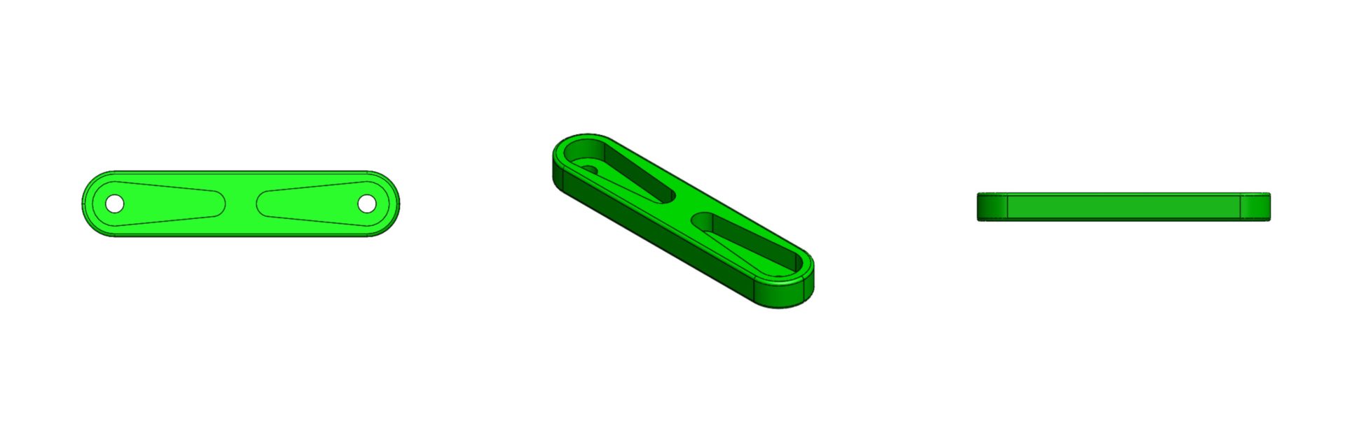
Fig.5 Servo Bracket
The ‘Servo Bracket” is a shorter version of part 0: servo hip and serves a similar purpose. This component mounts onto two servos that are located on the servo bands. This allows the second to the top servo to move the lower leg. This piece is located in the middle of the leg and connects the top and lower sections. This piece can be thought as the knee of the robot. Just like the other brackets, there are two cutout trenches that allow servo horns to be mounted and secured through a single screw. This piece can be varied in length to adjust the height of the robot and adjust the walking stride of the robot itself.
Part 4: Servo Wrap
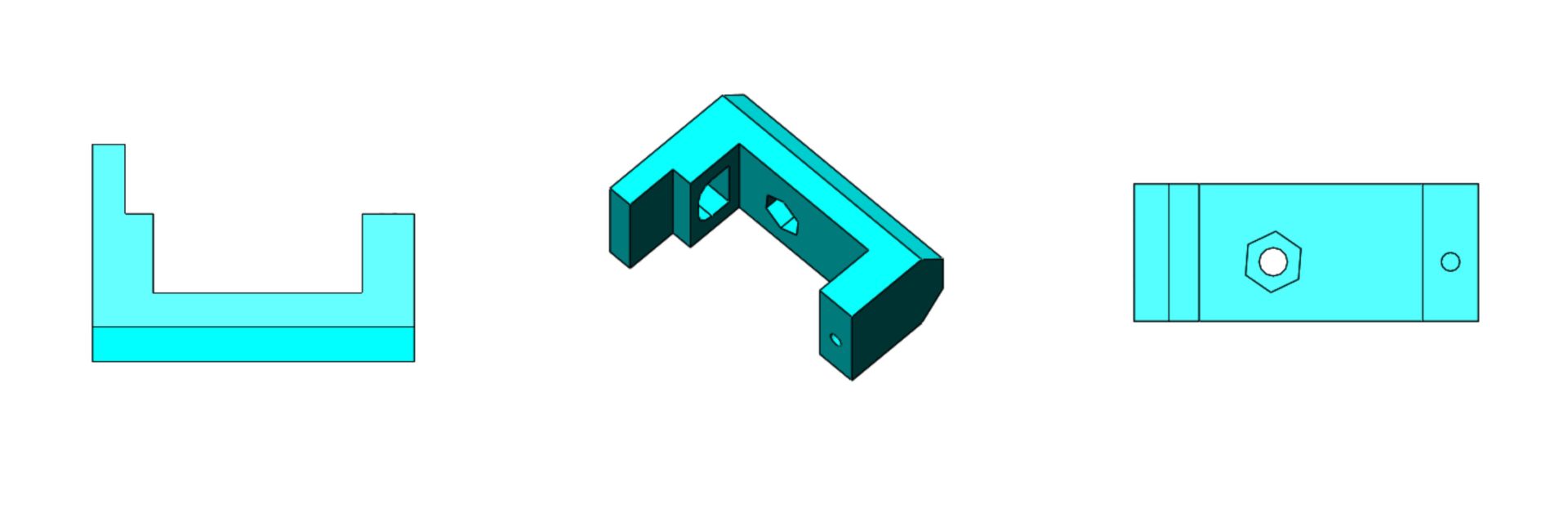
Fig.6 Servo Wrap
The “Servo Wrap” is a small piece that attaches the back of the hip servo (top leg servo) to be mounted onto part 5: Bearing Frame. It is connected via an M2 screw that is 18mm in length. The screw goes through the servo, through the servo band, and screws into this piece. A hole on the left side of the wall was added to allow the servo wires to feed through and connect back to the electronics. Notice there is a hexagon trench located near the middle of the part. This trench allows an M3 nut to be placed in that location and lets a screw to secure Part 4 with Part 5. Another key design feature is the chamfer cutout located on the backside of the part. This permits higher degrees of movement from the hip servos by at least 45 degrees more.
Part 5: Bearing Frame
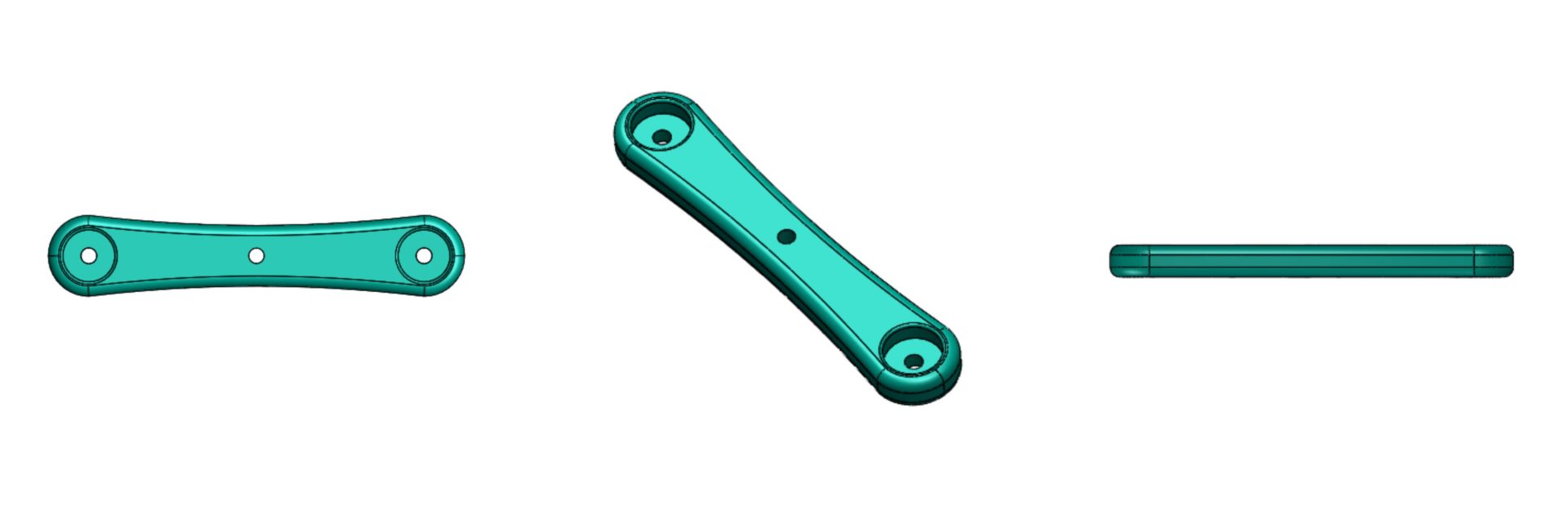
Fig.7 Bearing Frame
The “Bearing Frame” is a mirror-like component to part 0 as both pieces work together to provide the connection of legs to body. One of the key differences is that this piece contains two large circular trenches in which a bearing can fit onto. Using a 10mm circular bearing we place it on the part to provide free angular movement to the left and right sides of the pieces. Once the bearings are fitted inside, we can use M3X14 bolts to attach the servo wrap pieces to the left and right side of the Bearing Frame. Since the legs servos are already attached to the servo wrap we effectively attached the two legs to the body of the robot.
Part 6: Body Riser
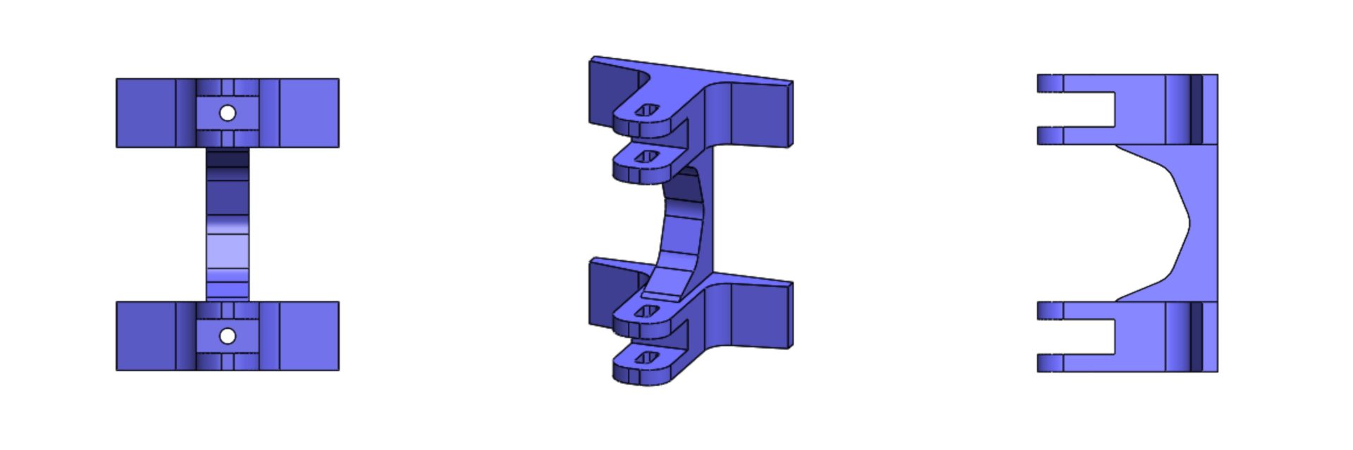
Fig.8 Body Riser
Micro FOBO mainly consists of a head and two legs but this part, body riser, can be considered the body of the robot. This component connects the two attached legs with the head. There are two fork-like structures located at the top of the piece that allows part 0 and part 5 to fit in snugly effectively connecting the two legs to this piece. Part 0 and part 6 are secured through a couple of M3 screws with an approximate length of 16 mm. The back side of this component is flat and has two holes for connecting to part 7 which is the electronics frame. The body riser can be increased in height allowing the robot’s head to be located higher above the legs. We can experiment with changing the height to allow shifting the robot’s center of mass higher or lower as needed.
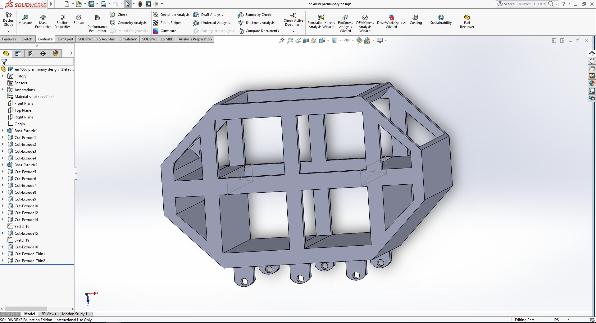
Part 7: Electronics Frame
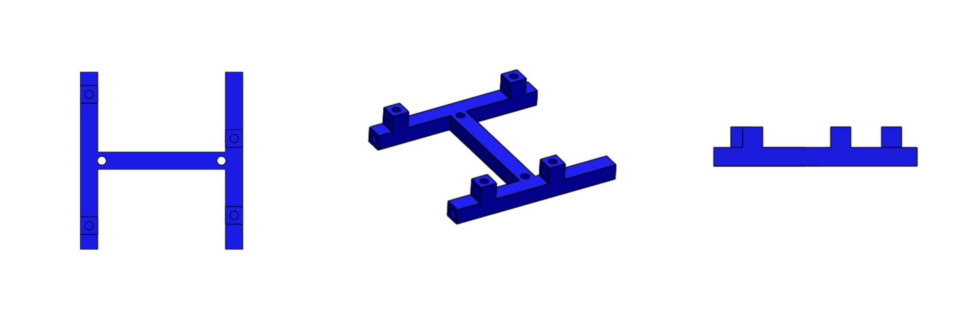
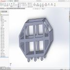
Fig.9 Electronics Frame
The Electronics Frame is a thin component that is responsible for connecting the PCB to the body riser. The PCB will contain four mounting holes which will allow the board to connect to this part. Note that the part contains extruded cubes that correspond to the location of the PCB hole mounts. These extruded cubes also have a hole cut out to fit M3 screws that secure the board in place. Finally, the part can be secured to the head via similar M3 screws on the side of the part and head
Part 8: Head
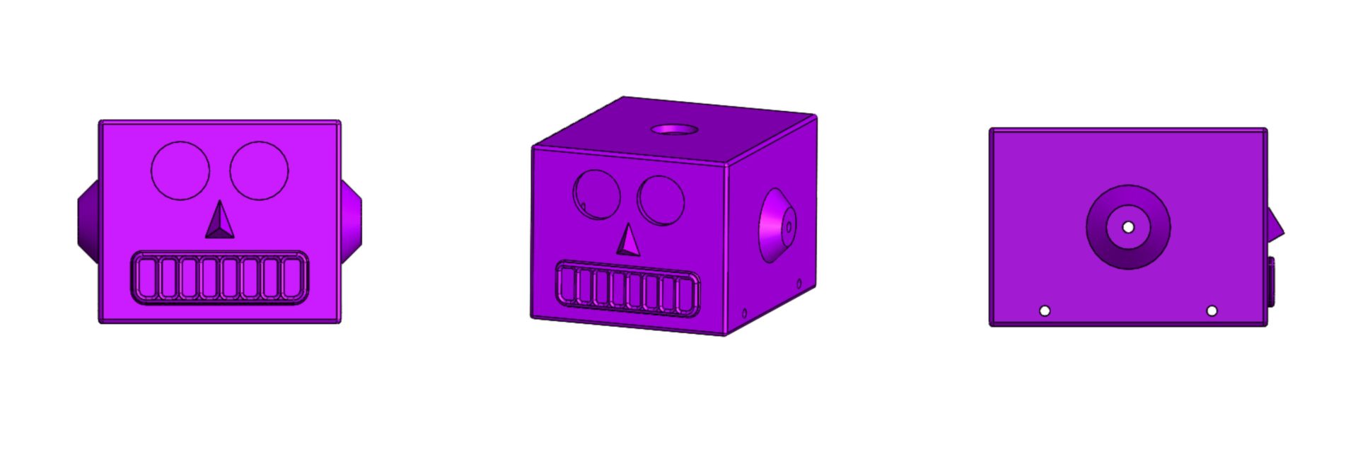
Fig.10 Head
One of the first challenges in creating a miniature FOBO we observed was that our robot would need to support large amounts of electronic components that used to be on the regular size FOBO. These electronics would need to be smaller in size or our head design would need to optimize to fit all the electronics. Our first design was based on the prediction that the new electronics would have a smaller footprint and thus the head of the Micro FOBO is much smaller. The exact dimensions can be found on the link below. Once the size of the head was set I began to look at some redesigns that I can implement to change the look and functionality of the robot’s head. That is when I stumbled on an image of a tin toy robot from the 1950s.

Fig.11 1950’s Tin Toy
As you can see from the image above this robot has a similar head as the FOBO which gave me the idea of emulating the design of the face. The ultrasonic sensor will take place as the robot’s eyes and the mouth and nose features would simply be aesthetics. Another thing that I noticed was that the tin toy contained antennas on the left and right side of the head. One of the redesigns I wanted to incorporate since the beginning was adding turn signals to the robot and the antennas can certainly be used for that. My idea is to have small 5mm red LED’s as the tip of the antennas that would blink indicating when the robot will turn and in what direction. Finally, we see that there is a small red light on top of the robot that can be designed to indicate on/off status of the robot.
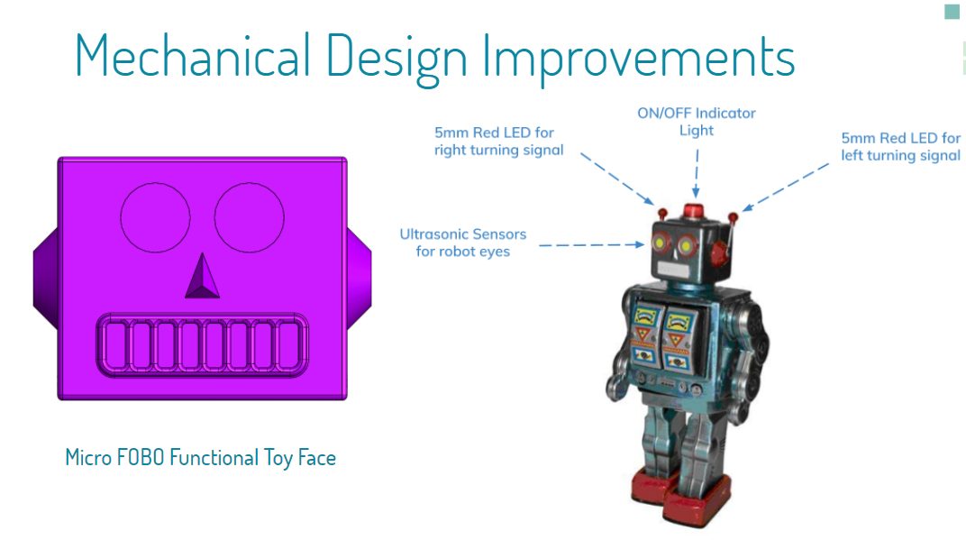
Fig.12 Mechanical Design Improvements