Goliath Fall 2017 – Robot Detection

Detection is a subroutine used in the collusion protocol. The subfunction will employ an IR proximity sensor, VL6180. The distance outputted  will be converted to a discrete value called squares which are dependent on the measured squares from the physical maze. Each side of the square is roughly 6.6 cms long meaning we have a […]

Goliath Fall 2017 – Mock-up Motor Test

The purpose of this post is to relay and archive  the results the Mock-up Motor specific testing. The measured results are the speed and the current draw. The Goliath will use 2 micro motor gear. It is also subject to a weight load of about 190 grams. This experiment was tested on a carpet surface.

HM-11 Bluetooth Module Soldering

Written by Melwin Pakpahan (Missions, Systems, & Test)

Description

This post will cover the assembly of the HM-11 Bluetooth module onto the 3DoT board. This module allows Bluetooth communication between the Arxterra app on an Android phone and the 3DoT board.

Pinout

According to the 3DoT v5.03 schematic, the functional pins of the HM-11 module used for the 3DoT Board are:

  • Pin 2: UART_TX
  • Pin 4: UART_RX
  • Pin 9: VCC
  • Pin 12: GND

Figure One shows the schematic of the HM-11 module taken from the 3DoT v5.03 schematic.


Figure One – Schematic of HM-11 module

Assembly

Assembly of the component is as follows:

  • Component is placed onto the board.
  • Flux is liberally applied to the pins, pads, and it surrounding areas.
  • A technique called drag-soldering is applied to solder the module on.
    • The tip of the soldering iron is tinned with an amount needed to cover all pins in a row.
    • Then, the tip of the iron is dragged across that row of pins.
  • Drag-soldering is repeated on the rest of the row of pins.

Finished assembly is shown in Figure Two.

Figure Two – Finished Assembly

Discussion

Pins 2, 4, 9, and 12 are the functional pins that must be soldered on to the board. In our case, all the pins are soldered onto the board to better hold the module in its place. However, this is not recommended because it makes the board more difficult to remove should there be any discrepancies. Therefore, only power (pin 9), ground (pin 12), transmit (pin 2), and  receive (pin 4) should be soldered.

References

[1] HM-11 – Reference One

[2] 3DoT v5.03 Schematic – Reference Two

[3] Drag-soldering – Reference Three

Color Sensor Shield: Fabrication, Integration, and Test

Approved By: Muhannad Al Mohamed, Charles Banuelos, Melwin Pakpahan

Written By: Muhannad Al Mohamed

Table of Contents

Color Sensor Shield Parts and Design

The parts used in the fabrication of each color sensor shields are the printed circuit board, electronic parts(two color sensors (BH1745NUC-E2), two LEDs (0603 package), two 150 Ohms resistors (0603 package), one 10k resistor (0603 package), one 47k resistor (0603 package), two 0.1 uF capacitors (0603 package), one MOSFET, one pin header), and Color Sensor Shield’s stencils along with solder.

Update: 12/6/2017

The design of the Color Sensor Shield is done using the free EagleCAD software. The schematics file of the circuit is attached to this link. The Printed Circuit Board layout is attached to this link. To open files the EagleCAD software needs to be installed.

Fabrication Place and Equipment

The fabrication of the CSS (Color Sensor Shield) is currently taking place in ET-111 room. The room is equipped with a microscope that can help in placing the parts on the shield. It also has an oven that can be used to melt the solder on the shield to hold the solder in place. Other useful amenities are available in the room such as a fridge to keep the solder cooled and ready to be used, and scissors and tape that can be used to hold the shield in one spot to place parts.

Fabrication and Integration Process

The fabrication process starts with holding the shield in one place and apply solder to it. Some unused PCBs are used to hold the shield in the center with duck tape applied to it.

Placing CSS in the centre of other PCBs to hold it

Solder is then placed on the board with a stencil on top of it using a card to evenly spread the solder. The microscope is then used to check if enough solder is applied to the PCB’s pads. Parts are then placed on the shield using tweezers to carefully put each part on the exact corresponding place.

Placing parts using tweezers

Checking if parts placed correctly

After making sure that the parts are placed on the correct place by looking at the shield through the microscope, the shield is then placed in the oven to let the solder flow and melt to make the connection to the parts.

Cooking the CSS in the oven

Since the CSS has parts placed on the top and bottom of it, only one side, of the shield, parts will be placed on put in the oven. The other parts on the other side will be placed and soldered by hand.

Final Product

Update: 12/6/2017

We were able to fabricate four shields with the parts provided.

Color Sensor Shield Top View

Color Sensor Shield Bottom View

Testing Process

The CSS will be tested once a fabrication of on shield is done. The shield will be connected to a 3DoT board and the I2C addresses would be checked. Codes of reading values within the registers in the Color Sensor IC should be applied to CSS through programming the 3DoT board.

Update: 12/6/2017

The first test on the shields was an inspection to locate any bridges present on the surface mount pads or dislocation of parts. If any bridges or dislocation are present, the shields would be fixed by desoldering the parts with a heat gun and soldering them again in place. By visual testing, we found that two shields had their LEDs light on and the other two were not functioning. Therefore, pin testing was done to check if the LEDs and the Color Sensor ICs had power in them. Surprisingly all the pins had power in them, therefore, any misfunctions could not be seen visually.

After checking that all parts are in place, the address checking code is applied to the Color Sensor Shield to make sure that the two sensors have the addresses of (0x38) and (0x39).

Another testing method to see if the Color Sensor Shields are actually working is by applying an Arduino code that uses the I2C library to read data from a register within the Color Sensor IC. The code attached reads data from the register that holds the value of the Red color.

Reading data from a register on the Color Sensor

This code was unable to read data from the Color Sensor Shield so another code is used. This code is optimized to measure colors from the color sensor shield.

Measurements

The measurements taken was applied by using a green surface with different locations.

Taking measurements of the color sensor shield

Perpendicular alignment of the measured surface to the color sensor shield

  • No change in green 115 at 13.5cm
  • at 9.5 cm, still 115
  • at 5.5cm, still 115
  • at 3.5cm, changed to 138
  • at 4.5cm, changed to 120
  • at 5cm, changed to 122
  • at 2 cm, changed to 192
  • at 1.5cm, changed to 259

Horizontal alignment of the measured surface to the color sensor shield

  • at 10cm, no detection
  • at 6cm, no detection
  • at 4cm, no detection
  • at 2cm, no detection
  • at 0.5, detection of 122

After taking measurements, we have concluded that the furthest distance for the color sensor to sense colors are 2cm perpendicularly and 0.5cm horizontally.


Final Deliverables

Update: 12/15/2017

After testing all Color Sensor Shields (CSS), there were no functional shields that can be accurately used to take measurements of colors in the maze. Two of the shields did not have a functional LEDs due to the burning of some parts during fabrication. The other two boards had functional LED but only one color sensor on one board was functional. The other color sensor on that board was intermittent and could not be relied upon for accurate measurements.

The possible reasons for the failure of producing functional Color Sensor Shields are solder bridges created during the soldering process and burnt parts during the repair process. The bridges could have been created during the placement of the parts on the board which was done by hand instead of using the pick and place machine or during the baking process to solder the parts to the board. The burning of extra parts occurred during the repair of certain parts that did not solder to the board. A heat gun had to be used to repair the boards which would cause surface burns and ultimate destruction of parts.


Fall 2017: ModWheels Cable Diagram


By: Natalie Arevalo (Design & Manufacturing Engineer)

Approved by: Lucas Gutierrez (Project Manager)

Introduction

Among the requirements set by the Robot Company, all projects must design and fabricate a custom PCB. However, due to the nature of our project and its design, a custom PCB is not necessary. In order to get the requirement of the custom PCB waived, the cable diagram for our project must be provided. The following is the cable diagram for our robot accompanied by a description. The description and diagram show that the components within our design can be directly connected into the 3Dot board without being interfaced through a custom PCB.  

Cable Diagram

The electrical components implemented in our design include one 3DoT board, one generic color shield, two motors each with an encoder, one servo, and one proximity sensor. The majority of the components listed can be directly connected into the 3DoT board. For instance, the generic color shield will be directly connected into the color shield header on the bottom side of the board. Additionally, the servo used in the design is also directly connected into the male servo header on the 3DoT board. Furthermore, the SDA and SCL connections on the proximity sensor are directly connected into the SDA and SCL female connections on the board. Also, the A channel connections on both encoders are directly connected into the A0 and A1 female connectors on the 3DoT. Then, the M1 and M2 connections of both encoders are placed into the female connectors for motor drivers B and A  on the board. The only connections placed indirectly into the 3DoT board are the ground and VCC connections for both of the encoders and the proximity sensor. These are placed into the 3.3 V and ground female connectors on the 3DoT board through some minor breadboarding. The two encoders on the motors, as well as the proximity sensor, have ground connections that are soldered in series on a through hole breadboard. A lead coming off of this breadboard, connected in series with the other ground connections, is then connected directly into the ground female connector on the 3DoT board. This set-up is then repeated for the 3.3 V connection on the proximity sensor and both VCC connections on the encoders. The lead coming off of their respective through hole breadboard is connected into the 3.3 V female connector on the 3DoT board. As shown below and detailed above, the majority of the connections needed for our components can be directly placed into the  board. The only exceptions are the VCC and ground connections for the encoders and proximity sensors. This is resolved by soldering these connections in series on a through hole breadboard and then connecting a lead off of that directly into the respective female connectors on the 3DoT board. With this small design implementation, all components are eventually connected directly into the board thus eliminating the need for a custom PCB.

Figure 1: Cable Diagram

Update

Due to unforeseen complications, 3DoT boards will not be available to be incorporated into our design. Instead, we will be executing the mission by incorporating break out boards that are connected on a breadboard. We will be using a ProMicro, a motor driver, as well as an HM 10 bluetooth module in place of the 3DoT board. We will also be using an IR shield instead of a color shield because there were complications with the fabrications of these as well. As a result, the cable diagram for our design has changed drastically. The new components and their incorporation onto the breadboard are shown in the updated cable diagram below.

Figure 2: Updated Cable Diagram


Read from EEPROM

By: Matt Shellhammer (Electronics & Control Engineer)

Approved by: Lucas Gutierrez (Project Manager)

Table of Contents

Introduction

When in play back mode the robots will be reading data that was previously stored in EEPROM while being controlled by the Arxterra App. What is being read from EEPROM is the direction that the robot was facing and the turn that the robot took at every decision point. This will allow the robot autonomously navigate throughout the maze since it will have the decision stored for every decision point throughout the robots path. For rooms such as hallways, corners, and a dead end the robot will always choose the same turn value so that does not require reading from EEPROM.

Methodology

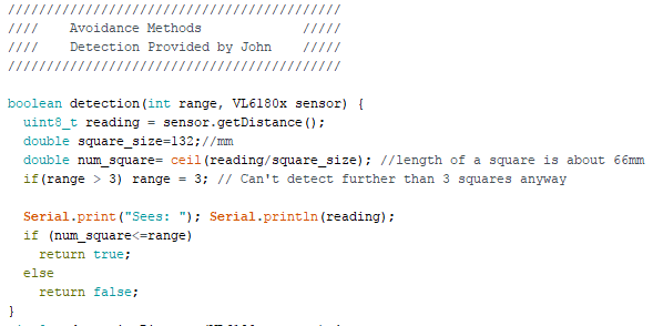
This software is developed to read data about direction and turn value every time a decision is made (room types 1, 2, and 4). It stores reads the data from EEPROM starting again at the address 0x0000. Every time the robot reaches a decision point, it will read the turn and direction value for that decision point and then use that to make its decision. The software in subroutines.ino file is the same as the subroutines.ino file in the blog post “Write to EEPROM”. The software specific to read EEPROM is in orange text within the EEPROM_Write.ino file below.

The roomType subroutine determines what room you’re in using “hitWall”, “rightHit”, and “leftHit”. “hitWall” ands the room value with a byte value from hit_table that is determined by the direction of the robot. The result will either be true or false depending if the robot is facing a wall or not. Then “rightHit” and “leftHit” just turns the robot and then implements hitWall again within the subroutines and determines if there’s a wall on the right and the left of the robot. This is then used to determine when a decision is required and when direction and turn must be read from EEPROM.

Data is read as follows:

Address Value
0x0000 Direction (decision 1)
0x0001 Turn (decision 1)
0x0002 Direction (decision 2)
0x0003 Turn (decision 2)
0x0004 Direction (decision 3)

Software

EEPROM_Write.ino (MAIN SETUP & LOOP)

////////////////////////////////////////////////////////////////
//  Name     : EEPROM Read maze data                          //
//  Author   : Matt Shellhammer                               //
//  Date     : 2 December, 2017                               //
//  Version  : 1.0                                            //
////////////////////////////////////////////////////////////////

#define __PROG_TYPES_COMPAT__ // __PROG_TYPES_COMPAT__
#include <avr/pgmspace.h>
#include <Robot3DoTBoard.h>
#include <EEPROM.h>
#include <Wire.h>
#include <Servo.h>
#include "maze.h"

void setup() {
  Serial.begin(9600);
  delay(5000);
}

void loop() {
  static uint16_t EEPROM_Idx = 0x0000;    // first EEPROM index is 0x0000
  static uint8_t type = 0;                // initially outside of the maze
  static bool decision;                   // create a variable called decision
  static myRobot_t robot_inst;            // create an instance of myRobot_t called robot_inst

  // No decision to be made when in a Hallway or outside of the maze (go straight)
  if ((type == 0)||(type == 5)){decision = false;robot_inst.turn = 0x00;}
  // No decision to be made when in a left corner (turn left)
  if (type == 3){decision = false;robot_inst.turn = 0x10;}
  // No decision to be made when in a right corner (turn right)
  if (type == 6){decision = false;robot_inst.turn = 0x01;}
  // No decision to be made when at a dead end (turn around)
  if (type == 7){decision = false;robot_inst.turn = 0x11;}
  else{decision = true;}

  // Call read data to EEPROM when at a decision point
  if ((decision == true)&&(EEPROM_Idx < 0x400)){
    // Call Arxterra custom command to request a turn value
    // Store dir facing and turn value
    uint8_t temp_dir = EEPROM_read(EEPROM_Idx);EEPROM_Idx++;
//    if (temp_dir != robot_inst.dir){//ERROR: Do something}
    robot_inst.turn = EEPROM_read(EEPROM_Idx);EEPROM_Idx++;
  }
    robot_inst = enterRoom(robot_inst); // Update robot_inst
    type = roomType(robot_inst);        // Determine room type
}

maze.h (Structure, array, and variable definitions)

struct coord_t{
  uint8_t row = 0x13; // Robot is initially outside of the maze
  uint8_t col = 0x00; // Robot is initially outside of the maze
};

struct myRobot_t{
  uint8_t dir = 0x03;   // Robot is initially facing north
  uint8_t turn = 0x00;  // First action is no turn
  coord_t maze;
  uint8_t room = 0x00;  // Initial room is empty
  uint8_t bees = 0x00;  // No bees present
};

const uint8_t hit_table[] PROGMEM =
  {0x08,  // South (dir == 0b00)
   0x02,  // East (dir == 0b01)
   0x04,  // West (dir == 0b10)
   0x01}; // North (dir == 0b11)

//Compass   S     E     W     N
//dir       00    01    10    11
const uint8_t turn_table[] PROGMEM =
          {0b00, 0b01, 0b10, 0b11, // 00 no turn
           0b10, 0b00, 0b11, 0b01, // 01 turn right
           0b01, 0b11, 0b00, 0b10, // 10 turn left
           0b11, 0b10, 0b01, 0b00  // 11 turn around
           };

//  row   col   dir
const int8_t map_table[] PROGMEM =
    {1  ,  0, // 00
     0  ,  1, // 01
     0  , -1, // 10
    -1  ,  0  // 11
    };

const int maze_length = 399;
const uint8_t theMaze[] PROGMEM =
// 00  01   02   03   04   05   06   07   08   09   0A   0B   0C   0D   0E   0F   10   11   12   13   14
{0x05,0x09,0x09,0x09,0x09,0x09,0x01,0x03,0x05,0x09,0x09,0x09,0x09,0x09,0x09,0x09,0x29,0x09,0x09,0x09,0x02,  // 00
 0x0C,0x09,0x09,0x03,0x05,0x09,0x0A,0x06,0x06,0x05,0x09,0x09,0x09,0x09,0x09,0x09,0x09,0x03,0x05,0x03,0x06,  // 01
 0x05,0x09,0x0B,0x06,0x06,0x05,0x09,0x0A,0x06,0x0C,0x09,0x09,0x09,0x09,0x09,0x01,0x0B,0x0C,0x0A,0x06,0x06,  // 02
 0x06,0x0D,0x09,0x0A,0x06,0x06,0x05,0x03,0x0C,0x09,0x09,0x03,0x05,0x09,0x09,0x0A,0x05,0x09,0x09,0x08,0x02,  // 03
 0x06,0x05,0x09,0x09,0x0A,0x06,0x06,0x0C,0x09,0x09,0x09,0x0A,0x0C,0x09,0x09,0x03,0x06,0x05,0x09,0x09,0x0A,  // 04
 0x06,0x0C,0x03,0x05,0x09,0x02,0x06,0x05,0x09,0x09,0x09,0x09,0x09,0x09,0x03,0x06,0x06,0x0C,0x03,0x05,0x03,  // 05
 0x06,0x05,0x0A,0x0C,0x03,0x06,0x06,0x06,0x05,0x01,0x03,0x07,0x05,0x03,0x06,0x06,0x06,0x05,0x0A,0x06,0x06,  // 06
 0x06,0x0C,0x09,0x03,0x0E,0x0C,0x08,0x02,0x06,0x06,0x06,0x06,0x06,0x06,0x0C,0x02,0x06,0x0C,0x09,0x02,0x06,  // 07
 0x06,0x05,0x0B,0x0C,0x09,0x09,0x09,0x08,0x02,0x06,0x06,0x06,0x06,0x0C,0x09,0x0A,0x04,0x09,0x0B,0x06,0x06,  // 08
 0x0C,0x08,0x09,0x09,0x09,0x09,0x01,0x01,0x02,0x06,0x0C,0x08,0x08,0x09,0x01,0x09,0x08,0x09,0x03,0x06,0x06,  // 09
 0x05,0x01,0x09,0x09,0x0B,0x07,0x06,0x04,0x02,0x0C,0x09,0x09,0x09,0x03,0x04,0x09,0x03,0x07,0x06,0x06,0x06,  // 0A
 0x06,0x0C,0x09,0x09,0x09,0x02,0x06,0x04,0x02,0x0D,0x09,0x09,0x09,0x0A,0x0C,0x03,0x06,0x06,0x06,0x06,0x06,  // 0B
 0x06,0x05,0x09,0x09,0x09,0x0A,0x06,0x0C,0x0A,0x05,0x09,0x09,0x09,0x09,0x03,0x06,0x06,0x06,0x06,0x06,0x06,  // 0C
 0x06,0x0C,0x09,0x09,0x09,0x03,0x04,0x09,0x09,0x08,0x0B,0x05,0x03,0x05,0x0A,0x06,0x06,0x06,0x06,0x06,0x06,  // 0D
 0x04,0x09,0x09,0x09,0x09,0x08,0x02,0x05,0x01,0x09,0x03,0x06,0x06,0x06,0x05,0x0A,0x0E,0x06,0x06,0x06,0x06,  // 0E
 0x06,0x05,0x09,0x09,0x09,0x09,0x0A,0x0E,0x06,0x07,0x06,0x06,0x06,0x06,0x06,0x05,0x09,0x0A,0x06,0x06,0x06,  // 0F
 0x06,0x0C,0x09,0x09,0x09,0x09,0x09,0x09,0x0A,0x06,0x06,0x06,0x06,0x0E,0x0E,0x06,0x05,0x09,0x0A,0x06,0x06,  // 10
 0x04,0x09,0x09,0x09,0x09,0x09,0x09,0x09,0x09,0x0A,0x0C,0x0A,0x06,0x05,0x09,0x0A,0x06,0x0D,0x09,0x0A,0x06,  // 11
 0x04,0x09,0x09,0x09,0x09,0x09,0x09,0x09,0x09,0x09,0x09,0x09,0x08,0x08,0x09,0x09,0x08,0x09,0x09,0x09,0x0A,  // 12
};

subroutines.ino

/*
 * Write data to EEPROM, NOTE: interrupts are disabled while writing
 * @param uiAddress 16 bit interger pointing to the address of the data to write
 * @param ucData 8 bit value signifying the data being written
 */

void EEPROM_write(uint16_t uiAddress, uint8_t ucData) {
  /*Store SREG value before we disable Interrupts*/
  char SREG_save = SREG;
  noInterrupts();
  /* Wait for completion of any Flash Write
        Note:Only necessary if Flash Memory Manipulation is taking place */
  while(SPMCSR &(1<<SPMEN));
  /* Wait for completion of previous write */
  while(EECR & (1<<EEPE));
  /* Set up address and Data Registers */
  EEAR = uiAddress;
  EEDR = ucData;
  /* Write logical one to EEMPE */
  EECR |= (1<<EEMPE);
  /* Start eeprom write by setting EEPE */
  EECR |= (1<<EEPE);
  /*Restore the SREG value*/
  SREG = SREG_save;
}

/*
 * Read data from EEPROM, NOTE: interrupts are disabled while writing
 * @param uiAddress 16 bit interger pointing to the address of the data to read
 * @return 8 bit value signifying the data that was read
 */

uint8_t EEPROM_read(uint16_t uiAddress) {
  /*Store SREG value before we disable Interrupts*/
  char SREG_save = SREG;
  noInterrupts();
  /* Wait for completion of any Flash Write
        Note:Only necessary if Flash Memory Manipulation is taking place */
  while(SPMCSR &(1<<SPMEN));
  /* Wait for completion of previous write */
  while(EECR & (1<<EEPE));
  /* Set up address register */
  EEAR = uiAddress;
  /* Start eeprom read by writing EERE */
  EECR |= (1<<EERE);
  /*Restore the SREG value*/
  SREG = SREG_save;
  /* Return data from Data Register */
  return EEDR;
}

myRobot_t enterRoom(myRobot_t robot){
  robot = turnInMaze(robot);
  robot = stepInMaze(robot);
  robot = roomInMaze(robot);
  return robot;
}

// Returns updated direction based on current direction and turn value
// values returned in robot structure
myRobot_t turnInMaze(myRobot_t robot){
  // index = 4*turn_val + dir_val
  uint8_t index = (robot.turn << 2) + robot.dir;
  robot.dir = pgm_read_byte_near(turn_table + index);
  return robot;
}

// Returns updated row and column values after taking a step in current direction
// values returned in robot structure
myRobot_t stepInMaze(myRobot_t robot){
  // index = 2*robot.dir
  uint8_t index = (robot.dir << 1);
  robot.maze.row += pgm_read_byte_near(map_table + index);      // Add either -1, 0, or 1 to current row value
  robot.maze.col += pgm_read_byte_near(map_table + index + 1);  // Add either -1, 0, or 1 to current column value
  return robot;
}

// Returns updated room and bees values using current row and column values
// values returned in robot structure
myRobot_t roomInMaze(myRobot_t robot){
  // index = 21*robot.maze.row + robot.maze.col
  uint16_t index = (21*robot.maze.row) + robot.maze.col;
  uint8_t maze_val = pgm_read_byte_near(theMaze + index);
  robot.room = maze_val & 0x0F;                   // clear upper nibble and store as the room value
  uint8_t temp_bees = (maze_val & 0xF0) >> 4;     // clear lower nibble and store as the temp bees value
  robot.bees += temp_bees;                        // add temp_bees to curret bees value
  return robot;
}

// Room Type subroutine
uint8_t roomType(myRobot_t robot){
  bool leftWall = leftHit(robot);       // Test if hiting left wall
  bool hit = hitWall(robot);            // Test if facing wall
  bool rightWall = rightHit(robot);     // Test if hiting right wall
  uint8_t room = (uint8_t(leftWall) << 2)|(uint8_t(hit) << 1)|uint8_t(rightWall);   // Convert to room type
  return room;
}

// Returns true if there is a wall and false if there is no wall
bool hitWall(myRobot_t robot){
  // index = dir_val
  robot = roomInMaze(robot);                                    // Determine room value
  uint8_t wallVal = pgm_read_byte_near(hit_table + robot.dir);  // Determine wall bit based on direction
  uint8_t outVal = bool(wallVal & robot.room);                  // Clear all bits other than the wall robot is facing
  if (outVal == 0){return false;}                               // If the robot is not hiting a wall outVal will equal zero
  else {return true;}                                           // and the subroutine will return false, else it returns true.
}

// Returns true if there is a wall and false if there is no wall
// on the right side of the robot
bool rightHit(myRobot_t robot){
  robot.turn = 0x01;          // Modify turn value to turn right
  robot = turnInMaze(robot);  // Call turnInMaze to turn the robot (virtually)
  bool hit = hitWall(robot);  // Test hit wall
  return hit;
}

// Returns true if there is a wall and false if there is no wall
// on the left side of the robot
bool leftHit(myRobot_t robot){
  robot.turn = 0x02;          // Modify turn value to turn left
  robot = turnInMaze(robot);  // Call turnInMaze to turn the robot (virtually)
  bool hit = hitWall(robot);  // Test hit wall
  return hit;
}

References

http://www.abc.net.au/news/image/2647380-3×2-940×627.jpg

Write to EEPROM


By: Matt Shellhammer (Electronics & Control Engineer)

Approved by: Lucas Gutierrez (Project Manager)

Table of Contents

Introduction

When in RC mode the robots will be controlled to travel through the maze with the Arxterra App through Bluetooth wireless communications. The robots are then required to memorize the path traveled and then repeat this path in playback mode. To make this possible information about the path must be saved while traveling through the maze. The information that will be saved is direction and turn so we know what direction the robot was facing and what direction it turned at each decision point. This data will be stored in EEPROM and then eventually read to implement playback mode.

Methodology

This software is developed to store data about direction and turn value every time a decision is made (room types 1, 2, and 4). It stores data into the EEPROM starting at address 0x0000. Every time a decision is made it stores the direction, increments the counter, stores the turn value decided on, and then increments the counter again for the next time a decision is made. This storage method decided upon is limited to 512 decisions since the address range of EEPROM is 0x0000 to 0x03FF, 1 KB, and we store two bytes for every decision therefore only 512 decisions can be stored within EEPROM.

Data Stored as follows:

Address Value
0x0000

Direction (decision 1)

0x0001 Turn (decision 1)
0x0002 Direction (decision 2)
0x0003 Turn (decision 2)
0x0004 Direction (decision 3)

Software

EEPROM_Write.ino (MAIN SETUP & LOOP)
////////////////////////////////////////////////////////////////
//  Name     : EEPROM Write maze data                         //
//  Author   : Matt Shellhammer                               //
//  Date     : 2 December, 2017                               //
//  Version  : 1.0                                            //
////////////////////////////////////////////////////////////////

#define __PROG_TYPES_COMPAT__ // __PROG_TYPES_COMPAT__
#include <avr/pgmspace.h>
#include <Robot3DoTBoard.h>
#include <EEPROM.h>
#include <Wire.h>
#include <Servo.h>
#include "maze.h"

void setup() {
  Serial.begin(9600);
  delay(5000);
}

void loop() {
  static uint16_t EEPROM_Idx = 0x0000;    // first EEPROM index is 0x0000
  static uint8_t type = 0;                // initially outside of the maze
  static bool decision;                   // create a variable called decision
  static myRobot_t robot_inst;            // create an instance of myRobot_t called robot_inst

  // No decision to be made when in a Hallway or outside of the maze (go straight)
  if ((type == 0)||(type == 5)){decision = false;robot_inst.turn = 0x00;}
  // No decision to be made when in a left corner (turn left)
  if (type == 3){decision = false;robot_inst.turn = 0x10;}
  // No decision to be made when in a right corner (turn right)
  if (type == 6){decision = false;robot_inst.turn = 0x01;}
  // No decision to be made when at a dead end (turn around)
  if (type == 7){decision = false;robot_inst.turn = 0x11;}
  else{decision = true;}

  // Call write data to EEPROM when a decision is made on the Arxterra App at a decision point
  if ((decision == true)&&(EEPROM_Idx < 0x400)){
    // Call Arxterra custom command to request a turn value (update robot_inst.turn)
    // Store dir facing and turn value
    EEPROM_write(EEPROM_Idx, robot_inst.dir);EEPROM_Idx++;
    EEPROM_write(EEPROM_Idx, robot_inst.turn);EEPROM_Idx++;
  }
  robot_inst = enterRoom(robot_inst); // Update robot_inst
  type = roomType(robot_inst);        // Determine room type
}

maze.h (Structure, array, and variable definitions)
struct coord_t{
  uint8_t row = 0x13; // Robot is initially outside of the maze
  uint8_t col = 0x00; // Robot is initially outside of the maze
};

struct myRobot_t{
  uint8_t dir = 0x03;   // Robot is initially facing north
  uint8_t turn = 0x00;  // First action is no turn
  coord_t maze;
  uint8_t room = 0x00;  // Initial room is empty
  uint8_t bees = 0x00;  // No bees present
};

const uint8_t hit_table[] PROGMEM =
  {0x08,  // South (dir == 0b00)
   0x02,  // East (dir == 0b01)
   0x04,  // West (dir == 0b10)
   0x01}; // North (dir == 0b11)

//Compass   S     E     W     N
//dir       00    01    10    11
const uint8_t turn_table[] PROGMEM =
          {0b00, 0b01, 0b10, 0b11, // 00 no turn
           0b10, 0b00, 0b11, 0b01, // 01 turn right
           0b01, 0b11, 0b00, 0b10, // 10 turn left
           0b11, 0b10, 0b01, 0b00  // 11 turn around
           };

//  row   col   dir
const int8_t map_table[] PROGMEM =
    {1  ,  0, // 00
     0  ,  1, // 01
     0  , -1, // 10
    -1  ,  0  // 11
    };

const int maze_length = 399;
const uint8_t theMaze[] PROGMEM =
// 00  01   02   03   04   05   06   07   08   09   0A   0B   0C   0D   0E   0F   10   11   12   13   14
{0x05,0x09,0x09,0x09,0x09,0x09,0x01,0x03,0x05,0x09,0x09,0x09,0x09,0x09,0x09,0x09,0x29,0x09,0x09,0x09,0x02,  // 00
 0x0C,0x09,0x09,0x03,0x05,0x09,0x0A,0x06,0x06,0x05,0x09,0x09,0x09,0x09,0x09,0x09,0x09,0x03,0x05,0x03,0x06,  // 01
 0x05,0x09,0x0B,0x06,0x06,0x05,0x09,0x0A,0x06,0x0C,0x09,0x09,0x09,0x09,0x09,0x01,0x0B,0x0C,0x0A,0x06,0x06,  // 02
 0x06,0x0D,0x09,0x0A,0x06,0x06,0x05,0x03,0x0C,0x09,0x09,0x03,0x05,0x09,0x09,0x0A,0x05,0x09,0x09,0x08,0x02,  // 03
 0x06,0x05,0x09,0x09,0x0A,0x06,0x06,0x0C,0x09,0x09,0x09,0x0A,0x0C,0x09,0x09,0x03,0x06,0x05,0x09,0x09,0x0A,  // 04
 0x06,0x0C,0x03,0x05,0x09,0x02,0x06,0x05,0x09,0x09,0x09,0x09,0x09,0x09,0x03,0x06,0x06,0x0C,0x03,0x05,0x03,  // 05
 0x06,0x05,0x0A,0x0C,0x03,0x06,0x06,0x06,0x05,0x01,0x03,0x07,0x05,0x03,0x06,0x06,0x06,0x05,0x0A,0x06,0x06,  // 06
 0x06,0x0C,0x09,0x03,0x0E,0x0C,0x08,0x02,0x06,0x06,0x06,0x06,0x06,0x06,0x0C,0x02,0x06,0x0C,0x09,0x02,0x06,  // 07
 0x06,0x05,0x0B,0x0C,0x09,0x09,0x09,0x08,0x02,0x06,0x06,0x06,0x06,0x0C,0x09,0x0A,0x04,0x09,0x0B,0x06,0x06,  // 08
 0x0C,0x08,0x09,0x09,0x09,0x09,0x01,0x01,0x02,0x06,0x0C,0x08,0x08,0x09,0x01,0x09,0x08,0x09,0x03,0x06,0x06,  // 09
 0x05,0x01,0x09,0x09,0x0B,0x07,0x06,0x04,0x02,0x0C,0x09,0x09,0x09,0x03,0x04,0x09,0x03,0x07,0x06,0x06,0x06,  // 0A
 0x06,0x0C,0x09,0x09,0x09,0x02,0x06,0x04,0x02,0x0D,0x09,0x09,0x09,0x0A,0x0C,0x03,0x06,0x06,0x06,0x06,0x06,  // 0B
 0x06,0x05,0x09,0x09,0x09,0x0A,0x06,0x0C,0x0A,0x05,0x09,0x09,0x09,0x09,0x03,0x06,0x06,0x06,0x06,0x06,0x06,  // 0C
 0x06,0x0C,0x09,0x09,0x09,0x03,0x04,0x09,0x09,0x08,0x0B,0x05,0x03,0x05,0x0A,0x06,0x06,0x06,0x06,0x06,0x06,  // 0D
 0x04,0x09,0x09,0x09,0x09,0x08,0x02,0x05,0x01,0x09,0x03,0x06,0x06,0x06,0x05,0x0A,0x0E,0x06,0x06,0x06,0x06,  // 0E
 0x06,0x05,0x09,0x09,0x09,0x09,0x0A,0x0E,0x06,0x07,0x06,0x06,0x06,0x06,0x06,0x05,0x09,0x0A,0x06,0x06,0x06,  // 0F
 0x06,0x0C,0x09,0x09,0x09,0x09,0x09,0x09,0x0A,0x06,0x06,0x06,0x06,0x0E,0x0E,0x06,0x05,0x09,0x0A,0x06,0x06,  // 10
 0x04,0x09,0x09,0x09,0x09,0x09,0x09,0x09,0x09,0x0A,0x0C,0x0A,0x06,0x05,0x09,0x0A,0x06,0x0D,0x09,0x0A,0x06,  // 11
 0x04,0x09,0x09,0x09,0x09,0x09,0x09,0x09,0x09,0x09,0x09,0x09,0x08,0x08,0x09,0x09,0x08,0x09,0x09,0x09,0x0A,  // 12
};

subroutines.ino

/*
 * Write data to EEPROM, NOTE: interrupts are disabled while writing
 * @param uiAddress 16 bit interger pointing to the address of the data to write
 * @param ucData 8 bit value signifying the data being written
 */
void EEPROM_write(uint16_t uiAddress, uint8_t ucData) {
  /*Store SREG value before we disable Interrupts*/
  char SREG_save = SREG;
  noInterrupts();
  /* Wait for completion of any Flash Write
        Note:Only necessary if Flash Memory Manipulation is taking place */
  while(SPMCSR &(1<<SPMEN));
  /* Wait for completion of previous write */
  while(EECR & (1<<EEPE));
  /* Set up address and Data Registers */
  EEAR = uiAddress;
  EEDR = ucData;
  /* Write logical one to EEMPE */
  EECR |= (1<<EEMPE);
  /* Start eeprom write by setting EEPE */
  EECR |= (1<<EEPE);
  /*Restore the SREG value*/
  SREG = SREG_save;
}

/*
 * Read data from EEPROM, NOTE: interrupts are disabled while writing
 * @param uiAddress 16 bit interger pointing to the address of the data to read
 * @return 8 bit value signifying the data that was read
 */
uint8_t EEPROM_read(uint16_t uiAddress) {
  /*Store SREG value before we disable Interrupts*/
  char SREG_save = SREG;
  noInterrupts();
  /* Wait for completion of any Flash Write
        Note:Only necessary if Flash Memory Manipulation is taking place */
  while(SPMCSR &(1<<SPMEN));
  /* Wait for completion of previous write */
  while(EECR & (1<<EEPE));
  /* Set up address register */
  EEAR = uiAddress;
  /* Start eeprom read by writing EERE */
  EECR |= (1<<EERE);
  /*Restore the SREG value*/
  SREG = SREG_save;
  /* Return data from Data Register */
  return EEDR;
}

myRobot_t enterRoom(myRobot_t robot){
  robot = turnInMaze(robot);
  robot = stepInMaze(robot);
  robot = roomInMaze(robot);
  return robot;
}

// Returns updated direction based on current direction and turn value
// values returned in robot structure
myRobot_t turnInMaze(myRobot_t robot){
  // index = 4*turn_val + dir_val
  uint8_t index = (robot.turn << 2) + robot.dir;
  robot.dir = pgm_read_byte_near(turn_table + index);
  return robot;
}

// Returns updated row and column values after taking a step in current direction
// values returned in robot structure
myRobot_t stepInMaze(myRobot_t robot){
  // index = 2*robot.dir
  uint8_t index = (robot.dir << 1);
  robot.maze.row += pgm_read_byte_near(map_table + index);      // Add either -1, 0, or 1 to current row value
  robot.maze.col += pgm_read_byte_near(map_table + index + 1);  // Add either -1, 0, or 1 to current column value
  return robot;
}

// Returns updated room and bees values using current row and column values
// values returned in robot structure
myRobot_t roomInMaze(myRobot_t robot){
  // index = 21*robot.maze.row + robot.maze.col
  uint16_t index = (21*robot.maze.row) + robot.maze.col;
  uint8_t maze_val = pgm_read_byte_near(theMaze + index);
  robot.room = maze_val & 0x0F;                   // clear upper nibble and store as the room value
  uint8_t temp_bees = (maze_val & 0xF0) >> 4;     // clear lower nibble and store as the temp bees value
  robot.bees += temp_bees;                        // add temp_bees to curret bees value
  return robot;
}

// Room Type subroutine
uint8_t roomType(myRobot_t robot){
  bool leftWall = leftHit(robot);       // Test if hiting left wall
  bool hit = hitWall(robot);            // Test if facing wall
  bool rightWall = rightHit(robot);     // Test if hiting right wall
  uint8_t room = (uint8_t(leftWall) << 2)|(uint8_t(hit) << 1)|uint8_t(rightWall);   // Convert to room type
  return room;
}

// Returns true if there is a wall and false if there is no wall
bool hitWall(myRobot_t robot){
  // index = dir_val
  robot = roomInMaze(robot);                                    // Determine room value
  uint8_t wallVal = pgm_read_byte_near(hit_table + robot.dir);  // Determine wall bit based on direction
  uint8_t outVal = bool(wallVal & robot.room);                  // Clear all bits other than the wall robot is facing
  if (outVal == 0){return false;}                               // If the robot is not hiting a wall outVal will equal zero
  else {return true;}                                           // and the subroutine will return false, else it returns true.
}

// Returns true if there is a wall and false if there is no wall
// on the right side of the robot
bool rightHit(myRobot_t robot){
  robot.turn = 0x01;          // Modify turn value to turn right
  robot = turnInMaze(robot);  // Call turnInMaze to turn the robot (virtually)
  bool hit = hitWall(robot);  // Test hit wall
  return hit;
}

// Returns true if there is a wall and false if there is no wall
// on the left side of the robot
bool leftHit(myRobot_t robot){
  robot.turn = 0x02;          // Modify turn value to turn left
  robot = turnInMaze(robot);  // Call turnInMaze to turn the robot (virtually)
  bool hit = hitWall(robot);  // Test hit wall
  return hit;
}

References

https://www.techworm.net/wp-content/uploads/2015/05/Untitled27-e1432324102995.png