ModWheels Power Budget

By: Andrew Yi (Mission, Systems, & Test Engineer)
Approved By: Lucas Gutierrez (Project Manager)

Introduction

The 3DoT Board is comprised of key components that each draw current from the battery.  The boost receives input from the battery directly, and in turn provides power to the LDO. The power report has been updated per the Division Manager and modified to each individual project.
Figure 1: Power Budget
Figure 2: Power Budget
The test report for the GM-6 motors can be seen here:
The test report for the servo can be seen here:
2 color sensors and 2 shaft encoders are being used on our toy robot and the totals have been placed in the spreadsheet.  The motors and the servo will be pulling most of the current from our system, but the tests show us that they won’t impact the project’s power.
Figure 3: Power Budget
Figure 4: Power Budget
The margins for the LDO, Boost, and battery allow for a large margin for additional components.  Power Budget 4.png shows the estimated battery run time of our toy robot.  With current components, the ModWheels robot has the power capabilities to accomplish the mission.

Calibration Of The Muse Laser Cutter

Written By: Lucas Gutierrez (Project Manager for ModWheels) & Charles Banuelos (Design & Manufacturing Division Manager)

Worked On By: Charles Banuelos (Design & Manufacturing Division Manager) & Lucas Gutierrez (Project Manager for ModWheels)

Calibration of The Muse Laser Cutter

After configuring the laser cutter for power-up, calibration of the Muse laser cutter can begin.  Instructions on how to configure the laser cutter for power-up can be found in the post below.

If properly configuring the laser cutter for power-up has not been performed yet, follow instructions on how to verify received components and additional materials needed for optimized use, which can be found in the post below.

Steps on how to calibrate the Muse laser cutter can be found through the Muse Laser Calibration Guide video, as well as the Muse Laser Cutter manual.  Links for each can be found below.

Muse Laser Cutter Manual

This calibration consists of aligning each of the three mirrors to match the guide red guide laser to the power laser (used for cutting).  Below is a summary of the steps performed to calibrate the Muse Laser Cutter.

  1. Power on the Muse laser cutter and allow initial power on calibration to finish
  2. Place a small enough piece of thermal paper to cover mirror 1 (upper left corner of the laser bed)
  3. Fire a test laser pulse (controlled by the touch-screen)
  4. Check burn patter (made by the test laser pulse) against the red guide laser dot
  5. If off, adjust red guide laser to the burn patter using the included allen wrench (guide laser located towards the back of the laser bed)
  6. Once adjusted, remove thermal paper and place new piece of thermal paper onto the second mirror
  7. Move laser arm to the farthest positive (+) y direction (towards the back of the laser bed)
  8. Repeat steps 3-4
  9. If off, adjust the first mirror so that the red guide laser matches up with the burn pattern (skip this step if they match)
  10. Move laser arm to the farthest negative (-) y direction (towards the front of the laser bed)
  11. Repeat steps 3-4
  12. If the two burns do not match up, repeat step 9 (skip this step if they match)
  13. Once adjusted, remove thermal paper and place new piece of thermal paper onto the third mirror
  14. Move laser arm to the farthest negative (-) x direction (towards the left of the laser bed)
  15. Repeat steps 3-4
  16. If off, adjust second mirror so that the red guide laser matches up with the burn pattern (skip this step if they match)
  17. Move laser arm to the farthest positive (+) x direction (towards the right of the laser bed)
  18. Repeat steps 3-4
  19. If the two burns do not match up, repeat step 16  (skip this step if they match)
  20. Once adjusted, remove thermal paper and place new piece of thermal paper onto the lens on the laser arm
  21. Repeat steps 3-4
  22. If off, adjust third mirror so that the red guide laser matches up with the burn pattern (skip this step if they match)

That concludes the initial calibration of the Muse laser cutter.


Fall 2017:

Calibration Method

After an initial configuration of the system, on Friday (11/03/2017) at 1 pm, a calibration of the laser cutter was completed.

This calibration consisted of aligning each of the three mirrors to match the guide red guide laser to the power laser (used for cutting).

The calibration was done by placing thermal paper onto the first mirror, firing a test burn, then confirming or realigning the red guide laser to the burn spot. This process was repeated for the extremes of the placement of the laser on the relative axis. This was performed on each mirror and was confirmed by a test cut.

Configuring Laser Cutter for Power Up

Written By: Lucas Gutierrez (Project Manager for ModWheels) & Charles Banuelos (Design & Manufacturing Division Manager)

Worked On By: Charles Banuelos (Design & Manufacturing Division Manager) & Lucas Gutierrez (Project Manager for ModWheels)

Table of Contents

Introduction

After verification of components, assembly of the laser cutter can begin.  For instructions on verifying received components and additional materials needed for optimized use, please refer to “Muse Laser cutter Parts Verification & Additional Purchase of Materials” blog post linked below.

Configuring Subsystems

To connect the subsystems to the laser cutter, we referred to the Muse Quickstart Guide, Muse Laser Cutting Manual, and Muse Unbox & Setup Video.  To configure the water cooler, we referred to the water cooler manual. Links can be found below, which is followed by a summary of the configuration that was performed.

Muse Quickstart Guide

Muse Laser Cutter Manual

CW-3000 Water Cooler Manual

Air Filter

After verifying all air filter parts have been received and have no damage, assembly can begin.  Connect the included power cable into the slot assigned to Exhaust Fan Power Outlet located on the back of the Muse laser cutter.  Then connect the ducting from Exhaust Flange (located on the back of the Muse laser cutter) to the intake of air filter using the included ducting clamps.

Air Pump

After verifying all air pump parts have been received and have no damage, assembly can begin. Connect the attached power cable into the slot assigned to Air Compressor Power Outlet located on the back of the Muse laser cutter. Then connect the air hose from Air Inlet (located on the back of the Muse laser cutter) to the output of air pump using the included air nozzle adapter.

Water Cooler

After verifying all water cooler parts have been received and have no damage, assembly can begin. Before connecting power to the water cooler, an initial rinse of the water tank helps to ensure no contaminants are within the water loop.  To rinse the internal water storage tank, unscrew the top water tank cap and partially fill the tank with a cup of distilled water.  Rotate and gently shake the water cooler to make sure the entire tank has been internally rinsed.  In a safe and proper area, unscrew the water drain outlet (located on the bottom backside of the water cooler). Once all the water has been drained, replace the water drain outlet. Once the rinse is completed, fill the internal water storage tank until the specified fill line (see user manual).  After screwing on the top water tank cap, connect the included power cable into a power strip. Then connect the water hose from Water Inlet (located on the back of the Muse laser cutter) to the Water Outlet of water cooler using the 1/2″ hose clamps to ensure a proper fit.  Separately connect the water hose from Water Outlet (located on the back of the Muse laser cutter) to the Water Inlet of water cooler using the 1/2″ hose clamps to ensure a proper fit.

Initial System and Subsystems Power-up

Once all parts have been correctly assembled, plug in the Muse laser cutter with the included power cable into a power strip.  To start the power-up process, power on the water cooler and ensure no water leaks from the water cooler and the Muse laser cutter.  Then, turn on the Muse laser cutter by moving the power switch (located on the back of the Muse laser cutter). After the Muse power-on calibration is complete, use the touch-screen to navigate to the settings of the laser cutter.  Once in the settings menu, select the laser tab. Once in the laser tab within the settings menu, enable the air pump and exhaust fan.  Verify that the air pump is working and that the air filter is powered on properly.  This concludes the initial system and subsystems power-up.


Fall 2017:

Introduction

After an verification of components, on Friday (11/03/2017) at 10 am, an initial configuration of the subsystems and the laser cutter was done.

Configuring Subsystems

Air Filter

After materials verification, we connected the power to the laser’s dedicated power source for the air filter. Later, the ducting for the air filter was installed on the air filter itself and the laser cutter’s exhaust port.

Air Pump

After materials verification, we connected the power to the laser’s dedicated power source for the air pump. Later, the air hose for the air pump was installed on the air pump itself and the laser cutter’s air pump intake. After testing, it was confirmed that there will be no need for noise dampening during the laser cutter’s operation.

Water Cooler

After materials verification, we connected the power to and external surge protector, which also provides power for the laser cutter itself. After a rinse of the internal water storage tank, the internal water storage was filled up with distilled water.  To insure no contaminant were introduced to the laser cutter, a closed loop filtering was performed on the water cooler.

Later, the water hose for the water cooler was installed on the water cooler itself and the laser cutter’s water cooler intake and outtake, with the use of additional clamps.

Configuring the Laser Cutter

After initial subsystem configuration, the laser cutter was powered on to verify that all subsystems were function properly.

Figure : Assembled Muse Laser Cutter

Encoder Trade-Off Study

By: Matt Shellhammer (Electronics & Control Engineer)

With collaboration by: Zach Oyog (Electronics & Control Engineer of Sojourner) 

Approved by: Lucas Gutierrez (Project Manager)

Table of Contents

Introduction

In the effort to find an effective set of encoders to use on the ModWheels cars and to strengthen the synergy between ModWheels and Sojourner a trade-off study was performed. This trade study was aimed to find an encoder that could satisfy the desired functionality while drawing low current and power minimize the effect on the power budget.

Discussion

In this study two encoder types were investigated in this study, optical encoders and Hall Effect encoders. Optical encoders are designed to transmit an infrared light and reflect light off the rotating encoder wheel and then receive that reflected light with a phototransistor and that then creates an analog signal. This also can be applied to a wheel that has a spinning disk attached to the shaft of the motor allowing for light to reflect back as the shaft rotates. Hall Effect encoders use multipole magnets attached to the shaft of the encoder and one or more Hall Effect sensors (a thin piece of rectangular p-type semiconductor). As the shaft rotates the Hall Effect sensors, through induction, convert the magnetic field into a voltage that can be read by the microcontroller. [1]

For the ModWheels car a different type of Hall Effect encoder was studied since the Sojourner project is using a micro metal gearmotor as opposed to the extended shaft GM6 motors that ModWheels will be using.

Specifications

Magnetic Encoder Pair Kit for Mini Plastic Gearmotors, 12 CPR, 2.7-18V [2]

Size: 20 mm X 16.5 mm

Weight: 2.4 g

Minimum operating voltage: 2.7 V

Maximum operating voltage: 18 V

Counts per revolution: 12 (6-pole magnetic disc with 2 channels)

Output: Digital


Optical Encoder Pair Kit for Micro Metal Gearmotors, 3.3V [3]

Size: 9.6 mm X 11.6 mm

Weight: 0.7 g

Voltage: 3.3 V

Average input current: 24 mA

Counts per revolution: 12 (3-tooth wheel) / 20 (5-tooth wheel)

Output: Analog

Conclusion

For ModWheels the more desirable encoder would be the Magnetic Encoder Pair Kit for Mini Plastic Gearmotors because these encoders are made specifically for the extended shaft GM6 gearmotors. Additionally, after discussing with Sojourner the two projects came to the conclusion to go with the respective Hall Effect encoders for the respective motors in an attempt to maximize project synergy.

References

[1] http://www.electronics-tutorials.ws/electromagnetism/hall-effect.html

[2] https://www.pololu.com/product/1523

[3] https://www.pololu.com/product/2591

Color Sensor Trade Study (With Cloth Maze)

By: Matt Shellhammer (Electronics & Control Engineer)

Approved by: Lucas Gutierrez (Project Manager)

Introduction

This trade study is a follow on study to the color sensor trade study which simply investigated the ranges at which the colors using electrical tape (vinyl) would be detected using the TCS34725 color sensor. In this trade study I borrowed the cloth maze from The Robot Company to run testing on it with the TCS34725 color sensor. The goal of this trade study is to help give the projects an idea of where exactly on their robots the color sensor should be mounted. Or the development team of the color sensor PCB where the color sensors should be mounted on the PCB.

Methodology

In this trade study I used two devices, the Arduino Uno, and the TCS34725 color sensor. I connected the color sensor to the Arduino Uno in the configuration shown in the table below. Additionally, to read the values from the color sensor I2C communication was used. To implement this communication the Adafruit Arduino I2C communication library was used, this library is available online on the Adafruit website.

Table 1: Interface Matrix

Arduino Uno pins

TCS34725 Color sensor pins
Vcc (3.3v) VIN

GND

GND
SDA (pin18) SDA
SCL (pin19) SCL


This experiment was configured similar to the original color sensor test, however the color sensor was instead this time held above the cloth maze. A piece of paper with measurement tick marks was then placed next to the maze to measure the distance from either the side of the color sensor or the distance away from the color sensor. This piece of paper was used since rulers have a gap between the beginning of the measurements and the end of the ruler, and in this experiment the measurement had to start at the maze (not above it). The paper ruler is shown below.

Figure 1: Paper ruler used to measure vertical and horizontal distance.


Now using the maze I tested the three colors on the maze: white, green, and brown to determine the optimal vertical distance (distance away from color sensor). I did this by determining where I got a peak measurement and then called that the optimal distance for that color. I also measured at what distance there was detection and at what distance there was significant detection. Significant detection is defined as reading a value greater than 1000 for any of the RBG values. The maze used is shown below and the results of the experiment are below the figure.

Figure 2: Section of the maze used showing the white, green, and brown used.

Table 2: Color and Distance Detection (Part 1)

Color Detecting

Detection distance

Significant detection distance (RGB values over 1000 recorded) Distance where max value achieved
White 8.9 cm 2 cm 1 mm
Brown 4.7 cm 0.5 cm 3 mm
Green 6.1 cm 1.6 cm 2 mm


After this test was preformed another test was performed to determine the optimal horizontal distance for the color sensor. This distance is more subjective since you want to be far enough away from the sensor to not always be detecting the lines however you don’t want the response time of your robot to be too slow. For this test I measured two distances for each color, I measured the point the color is detected as well as the point at which the amount of detection significantly spikes. The origin or zero value would be in the middle of the color sensor. I then did this from the left and the right side of the color sensor, the left and right side of the color sensor is defined as follows. In this test the color sensor was placed at 1 cm away from the maze using a stack of post it notes to elevate the sensor above the maze. I did this test only for colors green and brown because white isn’t relevant for our particular applications.


Figure 3: Test setup to show which side would be the right side of the color sensor vs which is the left.

Table 3: Color and Distance Detection (Part 2)

Color Detecting Detected horizontal distance (Top) Detected horizontal distance (Bottom) Detection spike horizontal distance (Top) Detection spike horizontal distance (Bottom)
Brown 1.2 cm 1.4 cm 3 mm 3 mm
Green 1.3 cm 1.3 cm 5 mm 5 mm


Conclusion

What can be inferred from this trade study is that a vertical distance from the color sensor within a range of 1 cm to 1 mm is a suitable range. Overall, it appeared to be that the closer to the maze (vertically) the stronger your reading would be. Additionally as long as the color sensor is at least a horizontal range of 3 to 5 mm away (zero being the center of the color sensor) from the lines there will not be any significant unintentional readings. However if trying to ensure no detection when driving straight, a distance of 9-10 mm might be desired. Testing with the project specific robot and software will also be an important factor when deciding the layout and placement of the color sensors. This trade study is to be used in supplement with testing to give the engineers a good starting point when designing the color sensor layout.

Electronic Components BOM and Order: Goliath

Written By: Muhannad Al Mohamed (Electronics & Control Division Manager)

Components

Goliath’s project uses electronic components listed in the figure below. However, an update should be made to this list in regards to the color sensing components. Since we will be using BH1745NUC IC in sensing color, the Adafruit TCS340725 should be changed along with the components of the generic color sensor. As seen on the list, some parts have been acquired by the project’s members; however, the rest should be ordered. The pricing also should be provided in order to sort all parts needed and their cost.

Update: 11/19/2017

The list for Goliath is mostly the same as listed above. However, there was one part that was added to it which is the LED Matrix (KWM-20882XWB-Y). The parts of the project are ordered and are expected to arrive the weak after Fall Break. The parts used in making the Color Sensor Shield are included as well.

Goliath ordered parts

Color Sensor Shield parts

Written By: Muhannad Al Mohamed E&C DM

Electronic Component BOM and Order: ModWheels

Written By: Muhannad Al Mohamed (E&C DM)

Components

The ModWheels project uses electronic components listed in the figure below. For now, the project is set on not making a custom PCB. However, if the members of the project decided to make a custom PCB, this list should be updated. Also, this list does not include the new color sensor (BH1745NUC) along with its related components. As seen on the list, some parts have been acquired by the project’s members; however, the rest should be ordered.

Update: 11/19/2017

The ModWheels project is still set in not making a custom PCB. The project does not need any new parts to be ordered. However, the parts of the new color sensor shield are added to the project’s list.

Color Sensor Shield parts

Written By: Muhannad Al Mohamed E&C DM

Electronic Component BOM and Order: PeteBot

Written By: Muhannad Al Mohamed (E&C DM)

Components

The PeteBot(3DoT Chassis) uses electronic components listed in the figure below. These parts include the electronic parts that would be used in making the project’s costume PCB as well. This list needs to be updated to include the new color sensor with its related components. As seen on the list, some parts have been acquired by the project’s members; however, the rest should be ordered.

Old PBot Parts list

Update: 11/19/2017

A detailed version of the parts list used by the PeteBot is added is provided in the figure below. All the parts used to make the custom PCB using the SAMBII are included too. These parts are being ordered by the members of the project are expected to arrive soon. Parts used in making the new Color Sensor Shield are included as well.

  • IC CONTROLLR LI-ION 4.2V SOT23-5 (296-27017-1-ND)
  • IC REG BOOST ADJ 1.2A SYNC 10SON (TB6612FNGC8ELCT-ND)
  • IC MOTOR DRIVER PAR 24SSOP (MCP73831T-2ACI/OTCT-ND
  • IC REG LDO 3.3V 0.5A SOT23-5 (576-1281-1-ND)
  • RF System on a Chip – SoC BLE 4.1 SOC Ultra Low Power  (556-ATSAMB11G18A-MUY
  • BATT HOLDER CR123A THRU HOLE (BH123A-ND
  • FUSE PTC RESET 8V .75A 1206 (F3370CT-ND
  • FIXED IND 4.7UH 640MA 220 MOHM (308-1947-1-ND)
  • FERRITE BEAD 120 OHM 0201 1LN (490-2557-1-ND
  • 0.1µF ±10% 16V Ceramic Capacitor X7R 0402 (1005 Metric) (490-3261-2-ND
  • 1.8pF ±0.1pF 200V Ceramic Capacitor A 0402 (1005 Metric) (478-6406-1-ND
  • 3.9pF ±0.25pF 200V Ceramic Capacitor A 0402 (1005 Metric) (478-6413-1-ND
  • 1µF ±20% 6.3V Ceramic Capacitor X5R 0402 (1005 Metric) (478-5315-1-ND
  • 2.2µF ±10% 6.3V Ceramic Capacitor X5R 0402 (1005 Metric) (478-7885-1-ND
  • 10000pF ±5% 16V Ceramic Capacitor X7R 0402 (1005 Metric) (478-3664-1-ND
  • 4.7µF Molded Tantalum Capacitors 6.3V 1206 (3216 Metric) 4 Ohm (478-8176-1-ND
  • plus/minus 20% Ceramic Cap X5R 0402 (478-10791-1-ND)
  • 1.2pF ±0.1pF 50V Ceramic Capacitor C0G, NP0 0402 (1005 Metric) (478-10145-1-ND
  • Aluminum Electrolytic Capacitors – SMD 10uF 63V (667-EEE-FK1J100P
  • LED RED CLEAR 0603 SMD (160-1447-1-ND)
  • LED YELLOW CLEAR 0603 SMD (160-1448-1-ND
  • LED GREEN CLEAR 0603 SMD (160-1446-1-ND
  • CONN USB MICRO B RECPT SMT R/A (609-4618-1-ND
  • SWITCH SLIDE SPDT 300MA 4V (563-1102-1-ND
  • 3nH Unshielded Multilayer Inductor 300mA 260 mOhm Max 0402 (1005 Metric) (712-1457-1-ND
  • 9.1nH Unshielded Multilayer Inductor 500mA 260 mOhm Max 0402 (1005 Metric) (490-8390-1-ND
  • 4.7µH Shielded Wirewound Inductor 500mA 240 mOhm 0603 (1608 Metric) (445-3607-1-ND
  • 3.3nH Unshielded Multilayer Inductor 300mA 190 mOhm Max 0402 (1005 Metric) (712-1416-1-ND
  • 2.7nH Unshielded Multilayer Inductor 300mA 170 mOhm Max 0402 (1005 Metric) (712-1415-1-ND
  • 1 kOhms ±5% 0.2W, 1/5W Chip Resistor 0402 (1005 Metric) Automotive AEC-Q200, Pulse Withstanding Thick Film   (RHM1002CT-ND)
  • 22 Ohms ±5% 0.2W, 1/5W Chip Resistor 0402 (1005 Metric) Automotive AEC-Q200, Pulse Withstanding Thick Film (RHM1012CT-ND
  • 1 kOhms ±5% 0.2W, 1/5W Chip Resistor 0402 (1005 Metric) Automotive AEC-Q200, Pulse Withstanding Thick Film (RHM1002CT-ND
  • 2 kOhms ±5% 0.1W, 1/10W Chip Resistor 0402 (1005 Metric) Automotive AEC-Q200 Thick Film  (P2.0MJCT-ND)
  • 2 MOhms ±5% 0.1W, 1/10W Chip Resistor 0402 (1005 Metric) Automotive AEC-Q200 Thick Film (P2.0KJCT-ND)
  • 220 kOhms ±5% 0.1W, 1/10W Chip Resistor 0402 (1005 Metric) Automotive AEC-Q200 Thick Film (P220KJCT-ND)
  • 10 kOhms ±5% 0.1W, 1/10W Chip Resistor 0402 (1005 Metric) Automotive AEC-Q200 Thick Film (P10KJCT-ND)
  • Thick Film Resistors 0.1watts 1Mohms 1% (660-RK73H1ETTP1004F)
  • 26MHz ±10ppm Crystal 12pF 60 Ohms 4-SMD, No Lead (SER4186TR-ND)
  • 32.768kHz ±20ppm Crystal 4pF 60 kOhms 2-SMD, No Lead (535-12373-1-ND)
  • VL6180X FlightSense™ Light, 3D Time-of-Flight (ToF) Sensor Evaluation Board (1528-1815-ND)


Updated PBot parts list

Color Sensor Shield parts

Written By: Muhannad Al Mohamed E&C DM

Electronic Component BOM and Order: Sojourner

Written by: Muhannad Al Mohamed (E&C DM)

Components

Sojourner uses electronic components listed in the figure below. However, an update should be made to this list in regards to the color sensing components. Since we will be using BH1745NUC IC in sensing color, the Adafruit TCS340725 should be changed along with the components of the generic color sensor. As seen in the list, some parts have been acquired by the project’s members; however, the rest should be ordered.

Old Sojourner’s parts list

Update: 11/19/2017

The parts list of Sojourner has changed. A Fuse part (1206L075THYR) is added to the list and the parts for the new Color Sensor Shield (Sensor shield using: BH1745NUC IC) are added too. The parts have been ordered and are expected to arrive the week after Fall Break.

Color Sensor Shield parts

Written By: Muhannad Al Mohamed E&C DM

Testing of the TCS34725 (Trade-off study)

Written by Zachary de Bruyn

Purpose

The purpose of this experiment was to test the TCS34725 RBG Color-to-Digital sensor to determine if it was applicable for the purposes of the EE400D project “PeteBot”. The testing included testing of the sensitivity of the sensor, its ability to distinguish difference between colors, and performing studies as to the limitation of the sensor.

DC Characteristics of the TCS

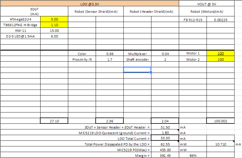
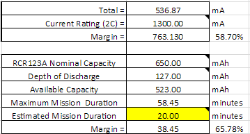
The TCS operates at a nominal voltage of 3-V with a maximum being 3.6-V. Depending on the state of the device, the current drawn ranges from 235-uA in an active state down to 2.5-uA in a sleep state.

DC Characteristics at the board level

The board is designed for usage with the Arduino where the VIN input is designed for 5-V, and draws XXXX A current.

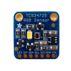
The TCS34725: The TCS34725 at the component level is the physical IC located on the breakout board that reads colors and digitizes them for the benefits of the user. Therefore when referring to the TCS34725, it is in reference to the actual IC, whereas when referring to the board, it is implied that we are talking about the entire board with all IC’s and passive components.

The TCS utilizes an I2C interface with a slave address as 0x29 in hexadecimal. Therefore in order to implement multiple TCS’ within the same I2C bus, certain precautions will need to be utilized, such as an I2C extender.

The block diagram of the TCS is shown below. From the diagram it can be seen that the light entering the sensor is filtered before going through four ADC afterwhich the signal is digitized into four different color data sections: Clear, Red, Blue, Green. The digitized data is then sent via I2C bus to the respective MCU being utilized; in this case the Arduino Uno.

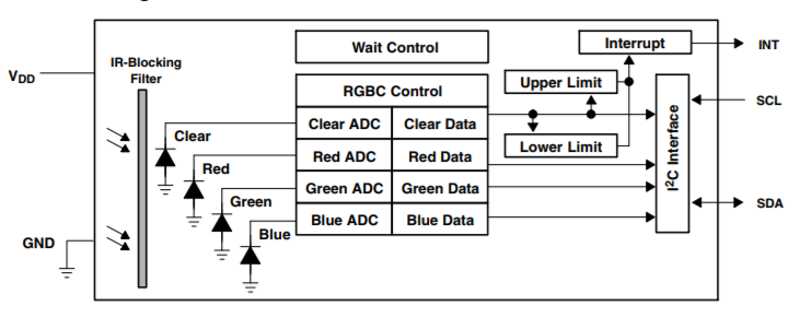
Figure 1: TCS Block Diagram

Breakout Board: The schematic of the breakout board is provided below, and is courtesy of Adafruit.

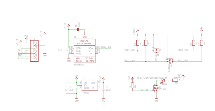
Figure 2: Breakout Board Eagle Schematic

As shown by the breakout board schematic, the board is powered by a 5-V input through the VIN pin on the board, and is then stepped down through an LDO (RT9193) to 3.3-V. The 5-V is also used for the source voltage for the two MOSFETs utilized in the circuit. The 3.3-V is then used as the gate voltage for the MOSFETs, and is also the input voltage necessary for the majority of the circuit including the TCS and LED MOSFET.  The breakout board also utilizes this 3.3-V and provides a 3.3-V output through the board (via pin 3, ‘+3V3’).

Test Set-Up

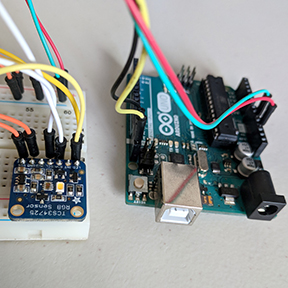
The purpose of this test was to determine the TCS’ ability to distinguish between colors. This test was performed by covering a square piece of cardboard with white tape, and then applying a half-inch strip of electrical tape down the center. The black tape is to simulate the lines of the maze, and the TCS’s ability to detect between colors. The basic test setup is given by Adafruit, where the VIN pin of the breakout board is powered via the 5-V of the Arduino, and the SDA and SCL inputs are connected to analog pins 4 and 5.

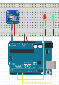
Figure 3: Fritzing Diagram

Next a circular wall was constructed to surround the breakout board so that testing can be done in a controlled environment which would mitigate the sensors ability to pick up any ambient light. This wall also allows us to maintain a static distance between the breakout board and the test strip that will be utilized to test the sensors ability to distinguish colors. Two LED’s were also utilized which would help determine if the correct value was being measured. When the correct color was measured (predetermined by me) the green LED would emit, else the red LED would light.

The code below was provided in the Adafruit library, and was modified in order to test the ability of the board to read colors.

/* Source provided by Adafruit and modified by Zach de Bruyn CSULB EE400D
   Connect SCL    to analog 5
   Connect SDA    to analog 4
   Connect VDD    to 5V DC
   Connect GROUND to common ground
 */

#include <Wire.h>
#include "Adafruit_TCS34725.h"

const int greenLED = 4;
const int redLED = 7;
const int fwd = 10;
const int rvs = 11;

/* Initialise with specific int time and gain values */
Adafruit_TCS34725 tcs = Adafruit_TCS34725(TCS34725_INTEGRATIONTIME_700MS, TCS34725_GAIN_1X);

void setup(void) {
  Serial.begin(9600);
  pinMode(greenLED, OUTPUT);
  pinMode(redLED, OUTPUT);

  if (tcs.begin()) {
    Serial.println("Found sensor");
  } else {
    Serial.println("No TCS34725 found ... check your connections");
    while (1);
  }

}

void loop(void) {
  readSensor();

 }

void readSensor (){
    uint16_t r, g, b, c, colorTemp, lux;

  tcs.getRawData(&r, &g, &b, &c);
  colorTemp = tcs.calculateColorTemperature(r, g, b);
  lux = tcs.calculateLux(r, g, b);

  Serial.print("Color Temp: "); Serial.print(colorTemp, DEC); Serial.print(" K - ");
  Serial.print("Lux: "); Serial.print(lux, DEC); Serial.print(" - ");
  Serial.print("R: "); Serial.print(r, DEC); Serial.print(" ");
  Serial.print("G: "); Serial.print(g, DEC); Serial.print(" ");
  Serial.print("B: "); Serial.print(b, DEC); Serial.print(" ");
  Serial.print("C: "); Serial.print(c, DEC); Serial.print(" ");
  Serial.println(" ");

 // digitalWrite(greenLED, HIGH);
  int color = r + g + b;

  Serial.print("Color: "); Serial.print(color); Serial.print(" ");

  // If black is sensed turn green LED on, else red LED is on.
  if (color < 8000 && color > 7000){
    digitalWrite(greenLED, HIGH);
    digitalWrite(redLED, LOW);
  }

  else{
    digitalWrite(redLED, HIGH);
    digitalWrite(greenLED, LOW);
  }

}

As seen in the redSensor() function. It is within this function that the sensor reads the individual digitized color. A variable ‘color’ was created which summed these values, and then these values were compared to a predefined range which would measure the black strip on the white background. In this case, the range was from 7000 to 8000.

Test Results

Video: Color Sensor Demonstration