Current Draw of GM-6 Motors

Written by Zachary de Bruyn

Purpose

The purpose of this testing is to determine the amount of current the motors draw when supplies with a CR123 – 3.7 V battery. The motors were inserted into the “3DoT Chassis” and to simulate the amount of current the motors draw when supplied with a load; in this case the weight of the chassis, running at 3.7 V.

Test Set-Up

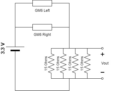
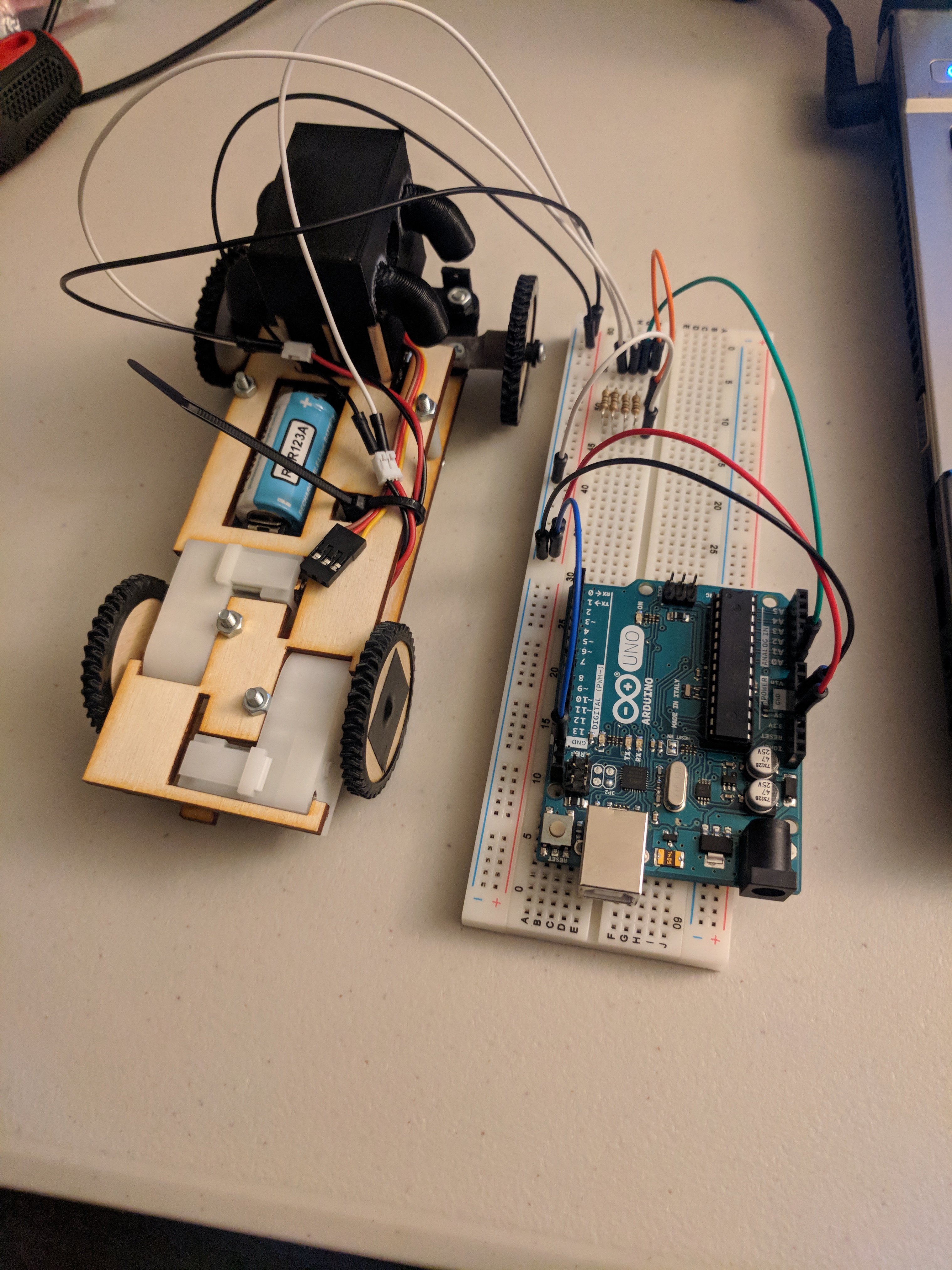
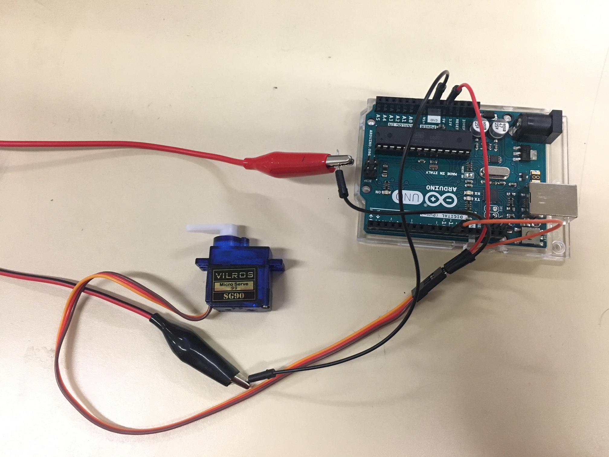
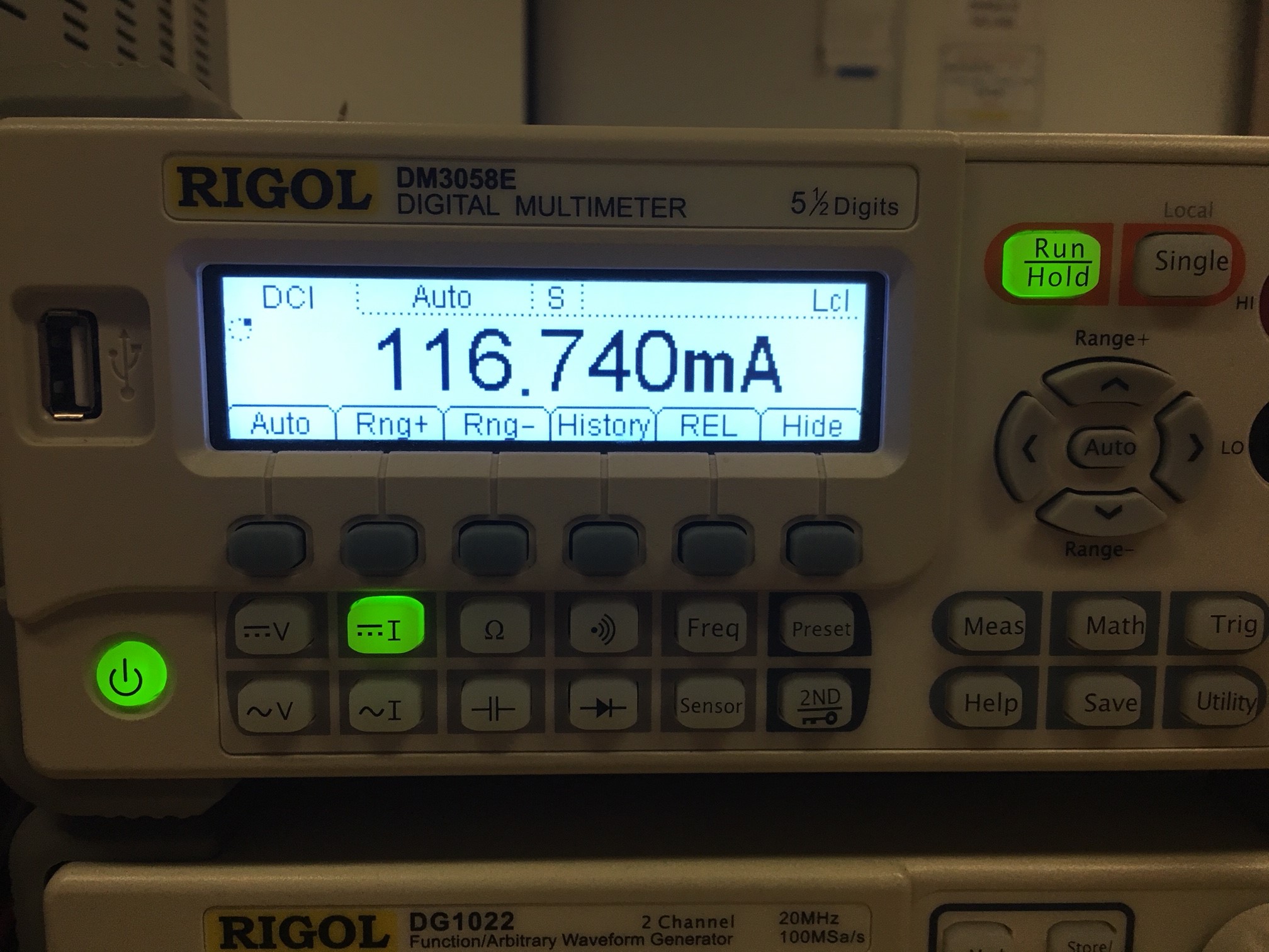
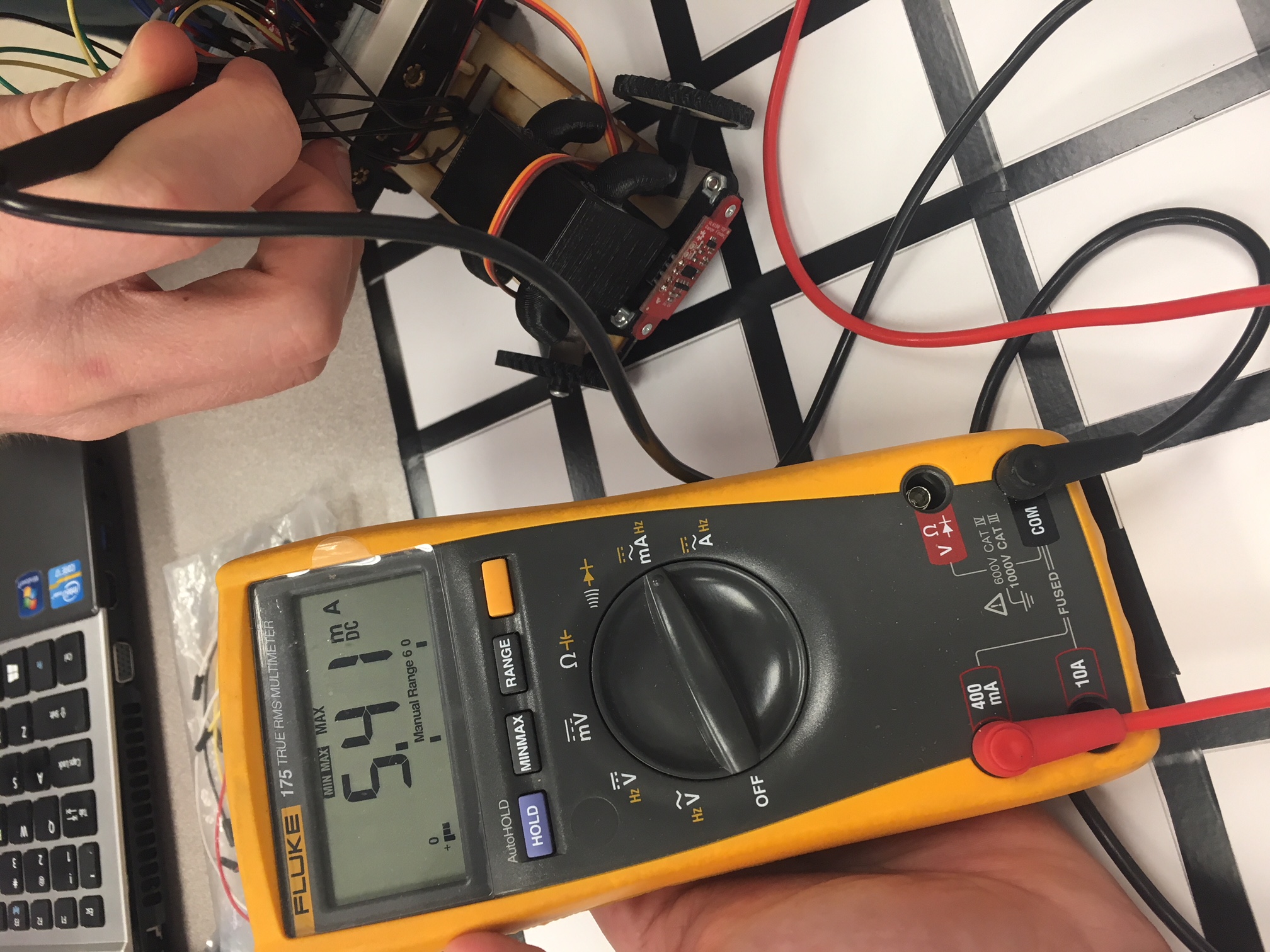
The test utilized was performed using the Arduino Uno and a voltmeter for redundancy. The setup is displayed below in figure 1. The two GM6 DC motors were inserted into the 3DoT chassis, as shown in the figures at the end of this blog. The chassis was then anchored by string to a desk to prevent it from moving while conducting the tests.

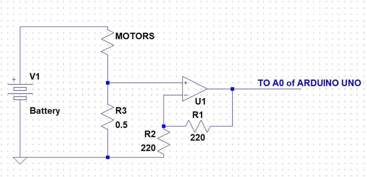
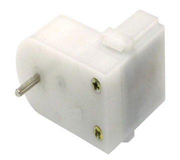
Figure One – Test Setup

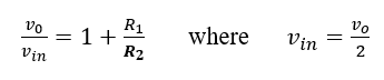
The motor load shown in figure 1 consists of two motors in parallel with a shunt resistor, R3, connected to the non-inverting input of an LM731 opamp The goal of this schematic was to drive a voltage gain at the output of the opamp that could then later be used to accurately measure the current draw of the two dc motors.

Going over some basic opamp characteristics:

  1. For ideal opamp the input resistance is infinite to both the inverting and noninverting inputs.
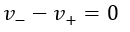
  2. The inverting opamp inputs drive each other to be equal, therefore:
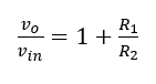
  3. For the inverting setup as displayed in figure 1, the gain is given as:

By recalling the three basics of the opamp listed above, we can then accurately measure the voltage (vin) that is measured across the 0.5-Ohm wire resistor. At the output of the opamp, a wire was connected to the A0 pin of the Arduino Uno. The 5-V supplied by the Arduino acted as the rail for the opamp and the CR123 battery was used as the dc input to power the load (motors). The following code was then uploaded through the Arduino IDE which allowed us to use the ADC from he A0 pin to measure the voltage at the output in 1s intervals.

/* Voltage Meter code Original source credit to https://www.allaboutcircuits.com/projects/make-a-
digital-voltmeter-using-the-arduino/

Modified for uses with RC123 Battery by Zach de Bruyn CSULB EE400D*/

const float referenceVolts = 5; // The measurement of your battery
const int batteryPin = A0; // battery is connected to analog pin 0

void setup()
{
Serial.begin(9600);
}

void loop()
{
int val = analogRead(batteryPin); // read the value from the sensor
float volts = (val / 1024.0) * referenceVolts; // calculate the ratio
Serial.println(volts); // print the value in volts
delay(1000);
}

A voltmeter was used to measure the voltage over the small resistance wire as a form of redundancy and accuracy checking of the Arduino code. The experimental measurement of the wire resistor was 0.5-Ohms.

Test and Results

The voltage was read from the Arduino serial monitor which averaged at 2.46-V. This is the “vout” from the gain equation earlier. The overall gain of the system was 2, where the resistors of equal value added to the 1 of the equation. Solving for vin, we find that the vin value is 1.23-V.

Recalling the three basic opamp rules earlier, we know that the infinite input resistances of the opamp causes no current to flow through the inputs, instead, all current goes through the 0.5-Ohm shunt resistor. Because the inputs drive each other to equal zero, the shunt resistor essentially acts as a voltage divider for the circuit. Therefore, the vin calculated, is the voltage over the shunt resistor. Performing Ohm’s law, we find that the current through the load is 2.46-A, where the current is assumed to be evenly split between the two motors in parallel, implying that each motor draws 1.23-A of current.

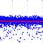
The voltages collected from the Arduino were then gathered into Matlab and analyzed through the following code:

clear all, clc
V_m = [ % Values collected from Serial Monitor];

x = smooth(V_m, 0.3, 'loess');

plot(V_m/0.5, '.b'); grid on;
hold on
plot(x/0.5, '.r', 'linewidth', 1.5)
hold off
xlim([0, length(x)])
legend('Raw Data', 'Smooth')
xlabel('Time - sec'); ylabel('A');
title('Arduino measurements')

As we can see from the data points collected from the Matlab plot, the current fluctuated between 2.46 and 2.47 A, with an average being 2.46-A. The raw data collected every second is displayed in blue, while the averaging data is displayed in red.

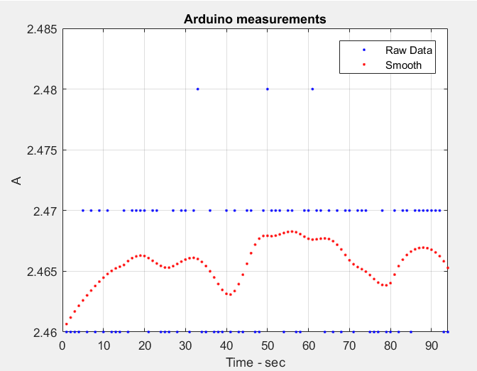
Figure Two – Plotted data with trend line

Pictures of Physical Test Set-Up

Not shown are the wheels or string which suspended the movement of the chassis, however, the general understanding of the setup can be achieved with the following pictures.

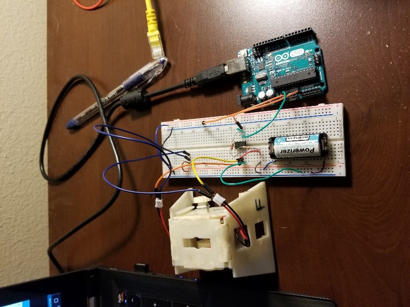
Figure Three – Physical setup of circuit


What to Record: Build Algorithm

By: Matt Shellhammer (Electronics & Control Engineer)

Approved by: Lucas Gutierrez (Project Manager)

Table of Contents

Introduction

To navigate throughout the maze we must record and update the information about the robots location within the maze. This will be done by using the maze stored in program memory, a two dimensional array to store information about direction and intersections, and a subroutine called “enterRoom”.

Methodology

To update the information about the maze as navigating throughout the maze I have developed a subroutine called “enterRoom”. What this subroutine does is calls three additional subroutines: “turnInMaze”, “stepInMaze”, and “roomInMaze”. I developed all of these subroutines using a structure called robot_inst that includes the following information: direction, turn, row, column, room, and bees. Then when calling these subroutines I simply send an instance of this structure to the subroutine and then store the result of enterRoom within that instance.

The subroutine turnInMaze uses the turn and direction values from the robot_inst structure and return a new direction value within robot_inst.

The subroutine stepInMaze uses the direction, row, and column values from robot_inst to return updated row and column values within robot_inst.

The subroutine roomInMaze uses the current row and column values to update the room and bees values within robot_inst.

Software

Main .ino file

////////////////////////////////////////////////////////////////
//  Name     : Update room                                                 
//
//  Author   : Matt Shellhammer                                                        
//
//  Date     : 18 October, 2017                                           
//
//  Version  : 1.0                                                                                      //
////////////////////////////////////////////////////////////////

#define __PROG_TYPES_COMPAT__ // __PROG_TYPES_COMPAT__
#include <avr/pgmspace.h>
#include "maze.h"

void setup() {
  Serial.begin(9600);
  delay(5000); 
}

void loop() {
  // Robot is outside of maze in the bottom left corner
  // Initialization within structure prototype
  static myRobot_t robot_inst;    // create an instance of myRobot_t called robot_inst
  static boolean newRoom = 0;
  static uint8_t room_idx = 0;
  // If we make a turn in the real world then we have to update robot_inst.turn
  // to match the turn exicuted in the real world.
  if (newRoom == 1){
    robot_inst = enterRoom(robot_inst);
    currRow = robot_inst.maze.row;
    currCol = robot_inst.maze.col;
    nextDir[room_idx] = robot_inst.dir;
    room_idx++;
    newRoom = 0;
  }
}

Virtual instructions

myRobot_t enterRoom(myRobot_t current){
  current = turnInMaze(current);
  current = stepInMaze(current);
  current = roomInMaze(current);
}

myRobot_t turnInMaze(myRobot_t current_1){
  // index = 4*turn_val + dir_val
  uint8_t index = (current_1.turn << 2) + current_1.dir;
  current_1.dir = pgm_read_byte_near(turn_table + index);
  return current_1;
}

myRobot_t stepInMaze(myRobot_t current_2){
  // index = 2*current_2.dir
  uint8_t index = (current_2.dir << 1);
  current_2.maze.row += pgm_read_byte_near(map_table + index);      // Add either -1, 0, or 1 to current
// row value.
  current_2.maze.col += pgm_read_byte_near(map_table + index + 1);  // Add either -1, 0, or 1 to current
// column value.
  return current_2;
}

myRobot_t roomInMaze(myRobot_t current_3){
  // index = 21*current_3.maze.row + current_3.maze.col
  uint16_t index = (21*current_3.maze.row) + current_3.maze.col;
  uint8_t maze_val = pgm_read_byte_near(theMaze + index);
  current_3.room = maze_val & 0x0F;                      // clear upper nibble and store as the room value
  uint8_t temp_bees = (maze_val & 0xF0) >> 4;     // clear lower nibble and store as the temp bees value
  current_3.bees += temp_bees;                            // add temp_bees to curret bees value
  return current_3;
}

Header file

// Autonoumous maze arrays
uint8_t currRow;
uint8_t currCol;
uint8_t nextDir[256] = {0};

struct coord_t{
  uint8_t row = 0x13;
  uint8_t col = 0x00;
};

struct myRobot_t{
  uint8_t dir = 0x03;   // Robot is initially facing north
  uint8_t turn = 0x00;  // First action is no turn
  coord_t maze;
  uint8_t room = 0x00;  // Initial room is empty
  uint8_t bees = 0x00;  // No bees present
};

//Compass   S     E     W     N
//dir       00    01    10    11

const uint8_t turn_table[] PROGMEM =
          {0b00, 0b01, 0b10, 0b11, // 00 no turn
           0b10, 0b00, 0b11, 0b01, // 01 turn right
           0b01, 0b11, 0b00, 0b10, // 10 turn left
           0b11, 0b10, 0b01, 0b00  // 11 turn around
           };

//  row   col   dir

const int8_t map_table[] PROGMEM =
    {1  ,  0, // 00
     0  ,  1, // 01
     0  , -1, // 10
    -1  ,  0  // 11
    };

const int maze_length = 399;

const uint8_t theMaze[] PROGMEM =

// 00  01   02   03   04   05   06   07   08   09   0A   0B   0C   0D   0E   0F   10   11   12   13   14
{0x05,0x09,0x09,0x09,0x09,0x09,0x01,0x03,0x05,0x09,0x09,0x09,0x09,0x09,0x09,0x09,0x29,0x09,0x09,0x09,0x02,  // 00
 0x0C,0x09,0x09,0x03,0x05,0x09,0x0A,0x06,0x06,0x05,0x09,0x09,0x09,0x09,0x09,0x09,0x09,0x03,0x05,0x03,0x06,  // 01
 0x05,0x09,0x0B,0x06,0x06,0x05,0x09,0x0A,0x06,0x0C,0x09,0x09,0x09,0x09,0x09,0x01,0x0B,0x0C,0x0A,0x06,0x06,  // 02
 0x06,0x0D,0x09,0x0A,0x06,0x06,0x05,0x03,0x0C,0x09,0x09,0x03,0x05,0x09,0x09,0x0A,0x05,0x09,0x09,0x08,0x02,  // 03
 0x06,0x05,0x09,0x09,0x0A,0x06,0x06,0x0C,0x09,0x09,0x09,0x0A,0x0C,0x09,0x09,0x03,0x06,0x05,0x09,0x09,0x0A,  // 04
 0x06,0x0C,0x03,0x05,0x09,0x02,0x06,0x05,0x09,0x09,0x09,0x09,0x09,0x09,0x03,0x06,0x06,0x0C,0x03,0x05,0x03,  // 05
 0x06,0x05,0x0A,0x0C,0x03,0x06,0x06,0x06,0x05,0x01,0x03,0x07,0x05,0x03,0x06,0x06,0x06,0x05,0x0A,0x06,0x06,  // 06
 0x06,0x0C,0x09,0x03,0x0E,0x0C,0x04,0x02,0x06,0x06,0x06,0x06,0x06,0x06,0x0C,0x02,0x06,0x0C,0x06,0x02,0x06,  // 07
 0x06,0x05,0x0B,0x0C,0x09,0x09,0x09,0x04,0x02,0x06,0x06,0x06,0x06,0x0C,0x09,0x0A,0x04,0x09,0x0B,0x06,0x06,  // 08
 0x0C,0x08,0x09,0x09,0x09,0x09,0x01,0x01,0x02,0x06,0x0C,0x08,0x08,0x09,0x01,0x09,0x08,0x09,0x03,0x06,0x06,  // 09
 0x05,0x01,0x09,0x09,0x0B,0x07,0x06,0x04,0x02,0x0C,0x09,0x09,0x09,0x03,0x04,0x09,0x03,0x07,0x06,0x06,0x06,  // 0A
 0x06,0x0C,0x09,0x09,0x09,0x02,0x06,0x04,0x02,0x0D,0x09,0x09,0x09,0x0A,0x0C,0x03,0x06,0x06,0x06,0x06,0x06,  // 0B
 0x06,0x05,0x09,0x09,0x09,0x0A,0x06,0x0C,0x0A,0x05,0x09,0x09,0x09,0x09,0x03,0x06,0x06,0x06,0x06,0x06,0x06,  // 0C
 0x06,0x0C,0x09,0x09,0x09,0x03,0x04,0x09,0x09,0x08,0x0B,0x05,0x03,0x05,0x0A,0x06,0x06,0x06,0x06,0x06,0x06,  // 0D
 0x04,0x09,0x09,0x09,0x09,0x08,0x02,0x05,0x01,0x09,0x03,0x06,0x06,0x06,0x05,0x0A,0x0E,0x06,0x06,0x06,0x06,  // 0E
 0x06,0x05,0x09,0x09,0x09,0x09,0x0A,0x0E,0x06,0x07,0x06,0x06,0x06,0x06,0x06,0x05,0x09,0x0A,0x06,0x06,0x06,  // 0F
 0x06,0x0C,0x09,0x09,0x09,0x09,0x09,0x09,0x0A,0x06,0x06,0x06,0x06,0x0E,0x0E,0x06,0x05,0x09,0x0A,0x06,0x06,  // 10
 0x04,0x09,0x09,0x09,0x09,0x09,0x09,0x09,0x09,0x0A,0x0C,0x0A,0x06,0x05,0x09,0x0A,0x06,0x0D,0x09,0x0A,0x06,  // 11
 0x04,0x09,0x09,0x09,0x09,0x09,0x09,0x09,0x09,0x09,0x09,0x09,0x08,0x08,0x09,0x09,0x08,0x09,0x09,0x09,0x0A,  // 12
};

3DoT v4.54 ModWheels Implementation

By: Matt Shellhammer (Electronics & Control Engineer)

Approved by: Lucas Gutierrez (Project Manager)

Introduction

ModWheels was given a 3DoT v4.54 board and we have attempted to do testing on this board to begin developing software and custom commands for the robot. When attempting to upload the 3DoT basic example from my computer and interface to the 3DoT v4.54 board through the Arxterra app to move the motors there appeared to be no functionality.

Methodology

After meeting with Chris to troubleshoot the issues I was able to upload code that moves the motors without interfacing through the Arxterra app. I still have not been able to upload software to the 3DoT board that will interface through the Arxterra app to move the motors.

I will now be going through the 3DoT training document section 12 ‐ Arxterra Bluetooth Wireless Communication and running tests following through this document to diagnose the current issues. Once I have determined the leading issue and I am able to interface the 3DoT board through the Arxterra app I will upload an updated blog post explaining the process and the problems solve/encountered.

How To Record & What To Record

By: Matt Shellhammer (Electronics & Control Engineer)

Approved by: Lucas Gutierrez (Project Manager)

Introduction

To navigate the maze autonomously we will have to store data about the path traveled while in RC mode (direction, row, & column). This data then be used when switching to RC mode to replicate the actions that were taken in RC mode.

Methodology

When navigating the maze in RC mode the robot should store the direction when it detects that it has entered a new room with an intersection and executes a turn. It should store the new direction that the robot is facing after executing the turn. This direction should be stored in a two dimensional array where the intersection number is in one row and the direction traveled for that intersection is stored in the next row. The robot should store the row and column in variables that are constantly being updated to allow for the robot to know where it is at any time. In addition when it completes the maze those variable can be used to verify it truly completed the maze. A subroutine can be executed when the maze was finished and the user exits (or stops) RC mode to store the final row and column value and check that the maze was completed.

Turns should be predefined by each project as a command that executes a right or left turn and then stores the new direction in the two dimensional array. This allows for turns to be executed in a single button push and makes determining when a turn was executed relatively straight forward.

Source Material

Featured Image: https://forums.xilinx.com/t5/Spartan-Family-FPGAs/S6-Multiboot-Golden-Image-Header-Redux/td-p/243836

Fall 2017: ModWheels Print Time

By: Natalie Arevalo (Design & Manufacturing Engineer)

Approved by: Lucas Gutierrez (Project Manager)

Table of Contents

Introduction

As set by the customer, there is a limit on the time allotted for the parts that will be 3D printed for the robots. The rule for 3D printing is that total print time must not exceed six hours, with no single part taking more than two hours to print. To ensure that ModWheels would not violate this print time rule, an estimation of the print time was initially made. This estimation was based on a preliminary test print of one part, provided by another project’s Design & Manufacturing Engineer, to estimate the print time for the total parts.  This front axle took 45 minutes to be printed, which became a gauge to which to make a rough estimate on the total parts. Afterwards, calculated estimation for print time for all parts were made using the Cura software. Once the 3D models were finalized and sent to be printed, a full rundown of labor, time, and cost were provided, which gives ModWheels final print time results.

Print Times

Estimated Print Times

Table 1: Estimated Print Times

Calculated Print Times

Figure 1: Axle Part 1 (Calculated time = 15 minutes; Time per part x 2 parts = 30 minutes total)

Figure 2: Axle Part 2 (Calculated Time = 5 minutes; Time per part x 2 parts = 10 minutes total)

Figure 3: Servo Holder (Calculated Time = 1 hour & 47 minutes)

Figure 4: Proximity Sensor Holder (Calculated Time = 21 minutes)

Final Print Times

Figure 5: Final Print Time

Conclusion

As part of the preliminary print time, it was estimated that the parts for our project would be around four hours. However, the print times for each part were still calculated using the Cura software which yielded a total print time of about two hours and forty-eight minutes. These calculations were made by the program when the printer was set as the Ultimaker 3D Printer, the materials as ABS plastic, and the material fill as second to most fine. Now, when the pieces were actually printed, they were printed on a Prusa 3D printer using PLA plastic. These changes adjusted the time it would take the parts to print. Additionally, time was also added in which the preprocessing and postprocessing of the parts took place. This added more time to the print time of the parts which gave a total of three and a half hours for all the parts to be 3D printed for the ModWheels project.   


Source Material

Featured Photo: https://embed-ssl.wistia.com/deliveries/6ab5496ae3a346c9a1a6a4911a59e2fc605008c8.jpg?image_crop_resized=1280×720

ModWheels Mock-up with Motor Specific Testing

By: Matt Shellhammer (Electronics & Control Engineer)

Approved by: Lucas Gutierrez (Project Manager)

Table of Contents


Introduction

When working with a 3DoT board we need to know the amount of current and power that all peripheral devices will be drawing. This is something that is very important for mission success and if we do not have enough power to complete the mission we will have to come up with alternate solutions to developing a successful power budget.

Methodology

In this motor specific test I will be testing the current draw of the two GM6 motors for the ModWheels car. The way this test was performed was using an Arduino Uno as a power supply for the two GM6 motors as well as a device for recording the voltage drop across a parallel combination of resistors. To measure the current drawn by the two GM6 motors I used the configuration shown in Figure 1 with two GM6 motors in parallel and then four 15 Ω resistors in parallel to create a small resistance (3.75 Ω) to measure the voltage across. To record the voltage across the resistors an analog pin on the Arduino Uno was used to read the voltage and then print that voltage into the Arduino serial monitor. Once the samples were recorded in the serial monitor I then copied those samples into a MATLAB matrix to plot the results. I ran this test for two cases; the first case was with no load (rear wheels removed) shown in Figure 2, and the second case was the full ModWheels load shown in Figure 3. The second case with the full load was performed with the help of another person to assist holding the breadboard while the car is driving straight.

Figure 1. ModWheels motor current draw test setup

Figure 2. ModWheels motor current draw test setup for no load


Figure 3. ModWheels motor current draw test setup for full load


Results

Both tests were ran for thirty seconds recording approximately 6500 samples each. The results were plotted in MATLAB shown in Figures 4 & 5. The average current in case one with no load was 182.43 mA and the average current in case two with full load was 190.74 mA.

Figure 4. ModWheels unloaded current draw MATLAB plot


Figure 5. ModWheels loaded current draw MATLAB plot


Software

To convert the digital input from a quantized value to an analog value the following equation was used:

The reference voltage was 3.3 volts using the AREF external reference voltage pin on the Arduino Uno. The samples were then divided by the parallel resistance to obtain the current drawn by the two GM6 motors and plotted in MATLAB.

Arduino:

////////////////////////////////////////////////////////////////
//  Name     : Motor Test using Arduino Uno                   //
//  Author   : Matt Shellhammer                               //
//  Date     : 28 November, 2017                              //
//  Version  : 1.0                                            //
////////////////////////////////////////////////////////////////

void setup(){
  Serial.begin(9600);
  // Set the PIN Mode
  pinMode(A0, INPUT);
  // Set Analog reference to AREF
  analogReference(EXTERNAL);
  delay(5000);
}

void loop(){
  float V = 3.3*analogRead(A0)/1023;
  Serial.print(V);Serial.print("\t");
}

MATLAB:

%% Motor Test Plots
clear,clc,close all
%%% Resistance: Four 15 Ohms resistors in parallel = 3.75 Ohms (Measured:
%%% 4.7 Ohms)
R = 4.7;
load('motortestdata.mat')
% Unloaded current (recoreded over 30 second interval)
unloaded_I = (unloaded_V./R)*1000; % Result is in mA
AvgUnloaded_I = smooth(unloaded_I, 0.1,'loess')';
avg_unloadedI = mean(unloaded_I);
figure(1)
plot(unloaded_I,'o','MarkerSize',5)
grid on;hold on
plot(AvgUnloaded_I,'r','linewidth',4)
title('ModWheels unloaded current draw')
ylabel('Current (mA)')
xlabel('Sample')
axis([1 6353 0 300])

loaded_I = (loaded_V./R)*1000; % Result is in mA
AvgLoaded_I = smooth(loaded_I, 0.1,'loess')';
avg_loadedI = mean(loaded_I);
figure(2)
plot(loaded_I,'o','MarkerSize',5)
grid on;hold on
plot(AvgLoaded_I,'r','linewidth',4)
title('ModWheels loaded current draw')
ylabel('Current (mA)')
xlabel('Sample')
axis([1 6543 0 300])

References

https://cdn.solarbotics.com/products/photos/a845e1c2e8a762bd5ef059938ba799aa/gm6-front-img_3140.JPG?w=800

ModWheels Servo Test

By: Andrew Yi (Mission, Systems, & Test Engineer)

Approved by: Lucas Gutierrez (Project Manager)

Table of Contents


Introduction

Servos are notorious for drawing large amounts of current and needs to be taken into account when using the v5.03 3DoT Board.  The servo pulls its power directly from the battery via the servo headers on the 3DoT Board.  This test will measure the current draw of the servo in different settings:

  1. -45 degrees to +45 degrees constant turning (worst case scenario)
  2. -10 degrees to +10 degrees constant turning (average case scenario)
  3. Idle current

During its navigation within the maze, ModWheels will be performing small adjustments to keep itself within the confines of the maze hallways.  This is the justification for test #2.  This test should pull the most current because of how servos work.  Servos encase a small DC motor that provides high RPM and low torque.  The mini gears allow the servo arm to swing at a lower speed, but provide a higher amount of torque.  


Test Setup

A handheld digital multi-meter (DMM) was connected in series with the ground wire to test the current draw during these tests.  These tests give an overview of the current being drawn and allow us to have an idea of the amount of current being drawn.  More in depth tests will follow.

Figure 1: Test Setup


Test Values

The following values are for each test with the DMML:

Test 1:

The servo was programmed to constantly shift from -45 degrees to +45 degrees.  This test is to check that our power isn’t adversely affected if the ModWheels toy car were to find itself in this situation (constant turning).  Wide turns should not pull as much current because of the rate of change being less frequent (compared to test #2).

Figure 2: Test 1

Test 2:

This is the test for the ModWheels’ “worst-case” current draw.  Since ModWheels will spend most of its time within hallways, the servo will be making small adjustments to make sure the parameters (distance from hedges) are met.  Since the servo arm will be going from -10 to +10 degrees at a rapid rate, the highest amount of current draw should be from this scenario.  

Figure 3: Test 2

Test 3:

The idle current is tested to see how much current is drawn when there are no commands being sent to the servo. This test is to ensure that the servo does not have issues during idle mode.  What we don’t want to see are sudden spikes in current draw when the servo isn’t receiving any commands.

Figure 4: Test 3

Conclusion:

Judging from the worst case scenario (Test #2), ModWheels should not have power issues with the servo, as it draws directly from the battery.  The current draw from the servo was set at 250mA because of the addition of load in the final toy robot.  

Electronic Component BOM and order: Generic Color Sensor Shield

Approved By: Muhannad Al Mohamed E&C DM, Charles Banuelos MFG DM

Designing The Color Sensor Shield

Charles Banuelos (MFG DM) and I have worked together to design the Color Sensor shield that would be used by the projects of the Robot Company. I was responsible for designing the schematic part and he was responsible for designing the layout part of the shield. The Shield is using two Color Sensing ICs (BH1745NUC) presented by Thomas Forman. This IC can be adjusted to have two different addresses, which makes I2C communication protocol usable while using two Color sensors.

Color Sensor Shield – Schematic

Color Sensor Shield – PCB layout

Written By: Muhannad Al Mohamed E&C DM

Updated: 11/20/2017


Color Sensor Shield Parts list

The parts used in making the Color Sensor Shield are listed below. They were ordered from digikey.com and has arrived. The parts will be used to fabricate and test the color sensor shield on Monday 11/27/2017.

Color Sensor Shield parts

Ordered parts’ Invoice


Written By: Muhannad Al Mohamed E&C DM

Muse Laser Cutter Parts Verification & Additional Purchase of Materials

Written By: Charles Banuelos (Design & Manufacturing Division Manager) & Lucas Gutierrez (Project Manager for ModWheels)

Worked on by: Charles Banuelos (Design & Manufacturing Division Manager), Lucas Gutierrez (Project Manager for ModWheels), & Vanessa Enriquez (Design & Manufacturing Engineer for Goliath)


Before the setup of the laser cutter, initial confirmation of all components need to be verified and made sure there were no shipping damage.  To verify this, a packing list should be included in the box.  To start the verification process, remove and document all components in an orderly fashion, ensuring no loss of components.


For the Muse Laser Cutter, components included:

  • Laser cutter (with power cable)
  • Instruction manual (Laser cutter manual & software operation manual)
  • Product registration
  • Warranty registration
  • Water cooler (with water hose & pump adapter)
  • Exhaust fan (with ducting)
  • Air pump (with air hose & air nozzle adapter)
  • Burn plate
  • Focus billet
  • Allen wrench
  • Thermal paper
  • Ethernet cable


Once parts have been verified and checked for damage, additional parts may need to be purchase in order to ensure proper performance.


For the Muse Laser Cutter, separately purchased parts included:

  • Water cooler
  • Air filter (with ducting)
  • 1/2″ Hose clamps
  • 3 Gallons of distilled water


There is a helpful un-boxing video for the Muse laser cutter.

YouTube setup link


Fall 2017:

An initial unpacking was completed by Prof. Hill. There was a meeting, occurring on Thursday(11/2/2017) at 3pm that verified that all parts of the laser were received. There was extra hose clamps purchased in order to secure all water hoses to the input and output of the coolant system. There was also distilled water purchased in order to run the coolant system properly.


Color Sensor Trade off Study

Written By

Charles Banuelos MFG DM

Muhannad Al Mohamed E&C DM

Table of Contents

Previous tests

The color sensor placement in relation to the PCB is very important. The distance testing that will be occurring will tell what is the best distance to place the color sensors on the PCB. The sensor placement will determine whether the robot will run smoothly along the hedges and not stop every couple of centimeters. These tests will also determine how big the PCB will be since the tests will show whether an I2C multiplexer is needed.

Matt Shellhammer conducted tests in relation to the the adafruit color sensor and forwarded me the results. The data states the distances to detect three different colors(Brown, White and Green). The code also tests the horizontal distances for the same three colors. The study states that the optimal distance vertically for all three colors is between 1mm and 2cm. The horizontal for all three colors should be between 3mm and 1.4cm. The second color sensor(BH1745NUC) will be tested in the same manner as this test.

Written By Charles Banuelos MFG DM


Testing Color Sensors


The adafruit TCS34725 color sensor had only one fixed address. This resulted a problem for the projects of the Robot Company since most of them are planning to use two color sensors. The problem with communicating with a specific device using I2C (Inter Integrated Circuit) protocol is that I2C have to address a device with a unique address and since using two adafruit TCS34725 color sensors have the same address, it would result a conflict of data being sent by those sensors when the micro-controller is trying to talk to one of them. Therefore, another solution was presented by Pr. Hill, which was to use the color sensor Thomas Forman is using. Thomas’ BH1745NUC  color sensor can be adjusted to have two different addresses. By connecting the “ADDR” pin in one of the BH1745NUC ICs to VCC and the other BH1745NUC “ADDR” pin to ground would result having two color sensors with two different addresses.

Written By Muhannad Al Mohamed E&C DM

Planned Testing

The color sensor shield that has two BH1745NUC Color sensing ICs needs to be tested. The connections of the pins should be tested using inputs preferably by a 3DoT board. If a 3DoT board were not available an Arduino Uno would be used with taking caution to the voltage to be 3.3V. Implementing Address checking codes should check the addresses of the two BH1745NUC Color sensing ICs. Data should be read and values of colors should be detected. Thomas Forman has ordered parts for his color sensor shield and since he is using the same BH1745NUC Color sensing IC, we would be able to test the parts.

After checking that the color sensor shield is working correctly, sensing colors from the maze should be tested.

Update: 11/29/2017

Parts, stencils, and solder have been ordered and received during the Fall Break. Charles Banuelos, Muhannad Al Mohamed, and Melwin pakpahan are currently fabricating the Color Sensor Shield. After fabrication is completed Charles Banuelos and Muhannad Al Mohamed will test the Color Sensor Shield. Soldered parts will be visually checked if they were placed correctly without any bridges or misplacement. Connecting the Color Sensor Shield to the 3DoT board should be tested by visually verifying that the pins of the shield are actually connected to the front header of the 3DoT board. Also, by applying an Arduino code to find specific I2C addresses using the 3DoT board, the two different I2C addresses should be checked. The Color Sensor Shield would be tested on how it can actually measure colors (intensity of different colors).

Written By Muhannad Al Mohamed E&C DM