Spring 2017 SpiderBot – DC Motor Noise Experiment

Table of Contents

By Nicholas Jacobs – Project Manager

By Shaun Pazos – E & C

Problem

Bluetooth wireless communication is subject to massive amounts of interference because of the high-volume traffic on the 2.4 GHz frequency band, and is also subject to the noise generated by DC motor voltage spikes from each commutator as the shaft turns. This added noise is believed to prevent Bluetooth connections from happening, and the chief reason for connection losses.

Procedure

Using a solderless breadboard and one GM3 DC motor, 5 volts was applied to the terminals of the DC motor. Configuring a Tektronix TDS 210 oscilloscope in the XY  display mode allows a user to generate a plot where one input is displayed on one axis and the other input is a function of the other input probe. While in this mode, I only measured one input in order to best measure the amplitude of the DC motor noise across the motor terminals.  Setting the input to be displayed on the y axis with no signal on the x-axis, will only display the vertical portion of the signal.

Results

This experiment was completed using three different ceramic capacitor values at a time, no capacitor, 0.1uF, 1uF and a 10uF.


No capacitor across motor terminal.


0.1uF capacitor across motor


1uF capacitor across DC motor


10uF capacitor across DC motor


We switched back to the XT input display mode. This measures one input signal versus the time axis (X). This displays the noise fluctuations over time.


Noise across DC motor as function of time with no capacitor.


Noised suppressed with 1uF capacitor.

Conclusion

As we can see,  adding a 1uF capacitor across the motor terminals significantly reduces the amount of noise generated from the DC motors. This discovery was implemented into our custom PCB design to reduce the same noise generated by our motors.

Adding capacitors isn’t the only way to reduce the amount of noise in SpiderBot’s design. Pololu wrote an article that suggests 3 additional ways to suppress and prevent noise intrusion such as twisting the motor wires which has also been implemented into SpiderBots design.

Pick and Place – Emergency Power Switch

By: Tyler Jones (Manufacturing)

In order for the pick and place machine to have a safe and orderly operation the pick and place needs to incorporate an emergency switch. This should be obviously labeled and easily accessible to the user. If something were to occur as the machine is operating it might take too long to disconnect the microcontroller located in the electronics housing. A large black button clearly labeled “STOP” was added to the exterior of the pick and place. The dimensions of the switch are included below in Figure 1.

Figure 1


There are two major power sources that are used in the pick and place machine. The first is a AC to DC power supply that connects the machine to an AC wall or power strip receptacle. Once converted to DC power, bundle of 2 wires feeds the Me Uno Arduino Uno shield. This then powers up both the arduino and shield on top of the arduino. All devices are run from power on the arduino or solenoid switch board circuit. For more information on how to connect the power supply and run the machine please read the instruction manual, or visit the INSTRUCTION MANUAL FOR PICK AND PLACE OPERATION. The other source of power that feeds the machine is the USB connection of +5V from the user’s computer to the pick and place. In testing the pick and place while operating it was found that the +5V is able to still have the code run for the pick and place. It does not however allow the motors, solenoid, or servo motors to run if the +12V power supply is disconnected.

Now by implementing a switch on the +12V line after the AC power has been rectified and converted, the user now has a way to easily stop all motion of the machine. The switch a black colored DPST (Double Pole Single Throw) switch. The switch is wired by splicing the power cord of the DC power supply at the DC end, and routing the power to the switch. In the “OFF” state the switch is open and nothing will run on the machine. In the “ON” state the power will connect to the Me Uno Shield and the machine will run. The Double Pole Switch allows 2 circuits to connect to the switch and the single throw controls the 2 circuits simultaneously. The second circuit is for the other arduino and second power supply if used. A simple diagram on the setup of a DPST switch is shown below in Figure 2

Figure 2

Pick and Place – 3DoT IC Tray

By: Tyler Jones (Manufacturing)

The pick and place needs to have a way that it can easily access all the integrated circuits, and components that cannot fit in SMT part reels. This means that an IC tray must be created to house all the components for the nozzle to pick up. The IC tray must also be very accurate in dimension that way there is no room for error for the nozzle to pick and place the part in the center of the part. The IC tray must also stand up off the picking surface and be able to to have small wells, or housings were the parts can fit into. The IC tray is shown below in Figure 1 It shows the basic dimensions of the overall build of the IC tray.

                                                    Figure 1

The 3DoT tray contains 22 unique part wells, as well as 6 copies. The copies of the wells exist on the tray because there are sometimes multiple of the same components necessary to complete the 3DoT board. The 3DoT board also contains components that need to be flipped or oriented at 45,90, or 180 degrees from the well. The A axis stepper motor accomplishes the task of flipping the component while it is already on the nozzle. This is done by programming the A axis stepper motor to turn using the GCODE commands. The A axis stepper motor is the axis that handles rotation of the parts, it also is connected to the nozzle and vacuum pump tubing. For further information on how to control the A axis stepper motor, or the design of the motors please refer to INSTRUCTION MANUAL FOR PICK AND PLACE OPERATION blog post, or the CALIBRATION blog post.

There was a problem in creating the wells of the IC tray. The first issue was that the Lulzbot TAZ 5 3D printer has an error of printing thickness of about 0.1-0.2mm. This means that after taking into account all the sizes of components an oversizing of about + 0.1 -0.4mm needs to be used in order to have the wells a little bigger than the part. Every part that goes onto the 3DoT tray was measured using calipers, and also cross-referenced with the datasheets from the manufactures. The following tables below in Table 1 Table 2 shows the size, part, number, description, dimension, error margin calculation, and other information for each part. The table is contained in the INSTRUCTION MANUAL FOR PICK AND PLACE OPERATION in order to aid the user in knowing where to place the components into the IC tray.

                                                                                                Table 1

                                                                                                 Table 2

The positions outlined in column 1 of Table 1 correspond to the positions used on the 3DoT board. They are organized from left to right and top to bottom, with the number of the part corresponding to the same number on the IC tray itself.

The 3DoT IC tray was designed so that the centerline of each part is consistent. This allows for much easier programming and calibration as the X coordinate does not move when the G CODE is running. Similarly, the height of the tray does not change which allows for the Z coordinate of the pick and place to not change. This also makes the machine much more time efficient. For information on troubleshooting the code corresponding to the 3DoT tray or how to calibrate the machine, please see the CALIBRATION blog post.


Spring 2017 BiPed – Working Prototype/Walking and Balancing Experiment

By: Alexander Clavel (Project Manager)

Approved By: Alexander Clavel (Project Manager)

Table of Contents

Introduction

This post will cover an updated design of the last prototype as there were issues with functionality and acceptability by the customer. From the last design we had, it did not account for shifting the center of mass at all and had no way to balance its self during each step. Instead it used overlapping feet in which case was pointed out by the customer as unacceptable. This new design incorporates a similar gear box as the last with modified feet and an added balancing system.

New Design

Figure 1

The main difference between with the new prototype is the ability to shift its center of mass. That was also the main issue with the customer as he pointed out the sloppy and sluggish walking movement of the last prototype. Figure 1 shows what the new design is centered upon which is a tilt box with a moving ball bearing. The idea behind it is that as the BiPed takes each step, the box will tilt and roll the weighted ball to shift the center of mass onto the other foot. Timing was a big issue with this design as the mass had to be shifted just as the opposite foot was being planted to become the main support. If it was done too early or too late then the robot would have fallen over.

Another central design change is that instead of putting the DC motor slightly to the side, I put it directly into the middle as shown in Figure 3 below. This plays an important role in keeping the center of mass in the center and making it easier to shift the mass from one foot to the other. In this entire system as shown in the picture, the DC motor is what takes up most of the weight. As it is, the entire system weighs less than 200 g. What this means for the robot is that most of the weight is placed lower to the ground. This makes it easier to achieve static walking and keeps it more balanced as opposed to placing most of the weight at the top.

Method of Balancing

Figure 2

Figure 3

Figure 4

Figure 2 and 3 shows how the robot would stand on one foot to stay balanced. In figure 2, the box is shown to be tilted and in which case the ball bear is sitting on the left side (right side of the picture) of the robot allowing it to stand only on the left foot. Figure 4 shows the placement of the bearing  when shifting to one side. The feet in the images are a “C” shaped configuration, but it should not be confused with overlapping as in the last prototype. It is to be noted that the shape of the foot could be manipulated very easily, but for the sake of testing how balanced it would be, they were made to be large enough to be certain that it would cover wherever the center of mass shifted to.

This was the starting point to moving forward with the product. There are requirements stating that the BiPed should be able to statically walk which by definition is being able to maintain it’s balance throughout each stage of its walking. It should also still be able to stay upright even when power is shut off. This design evidentally works as shown in the pictures as there is not power attached to the robot but still is able to remain standing.

Walking & Static Balance Experiment

The design as shown in the figures above was not enough to keep it walking continuously. There was another CAM that was needed to be able to tilt the box back and forth. The completed prototype and design is shown in Figure 5 below.

Figure 5

Figure 5 shows the Biped in mid step as it starts to lift up its right foot (left side of the picture) and starting to shift its weight. The leg CAMs and the box CAM are all connected through to the same motor and share the same gear ratio so that the rotational speed is synced perfectly. As the feet are turning, the small pegs on the long metal shaft are rotating at the same rate. The position of the pegs is what allows for the shifting of the weight at the opportune moment. As a peg completes a rotation, the more elongated part of the peg will make contact with the box and tilt it up inevitably rocking the ball bearing to the opposite side. This took much trial and error to find the optimal positioning.

Once the optimal position was found, I connected the motor to the battery and let it run freely. The result was that it walked exactly as I wanted it and it was able to stay stable throughout the entire walk. Here a short video can be found as to the actual walking footage and balancing test.

Conclusion

In the end, static walking had been achieved but can still be improved on. The robot is able to statically walk but the inertia of the moving ball does seem to have a slight affect on the robot as it rocks the biped slightly. It is still able to walk in a straight line but it can be improved upon. The final design should include something to dampen the ball bearing like perhaps a sponge or spring as to soften the momentum. This should prevent the robot from any sort of falling due to any kind of sideways momentum.

Spring 2017 BiPed – Servo Turning Test

By: Jacob Cheney (Systems)

Approved By: Alexander Clavel (Project Manager)

Introduction

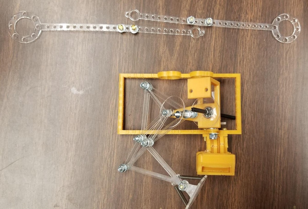
Based on mission objectives, where the BiPed has to maneuver through a maze in order to evade the Velociraptor, it is imperative that the BiPed is able to turn efficiently. Accomplishing this task is not as easy as it seems, as a bipedal itself must maintain balance at all times. The idea we came up with is to place one servo at the bottom of each leg to act as an ankle. Unlike a human ankle, these ankles will be able to turn 180 degrees to ‘twist’ the robot around to its new direction. Once the robot achieves its new desired orientation, it will take a step with the other foot and simultaneously reorient the original turning foot back to its starting position. This is required because the servos we are using can only turn 180 degrees.

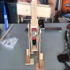
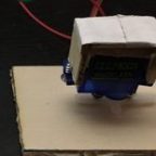
In this section I will be discussing the code in detail and how it will translate to our mechanical design. For testing purposes, the only materials used were an Arduino Uno and a Hextronic HXT900 hobby servo that was attached to a square piece of hobby wood, acting as a foot. The V+ of the servo was connected to the 5V terminal, ground to GND and the signal pin was connected to digital pin 10.  This setup is shown below.

Code/Tests

Figure 1: Servo to Arduino Connections

Beginning with the initialization part of the code we start by including the servo.h file, which includes most of the commands we will be using. Then we defined our left and right servos and set our initial positions that we wanted our servos to start at.


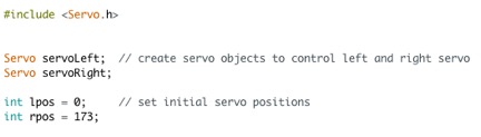
Figure 2: Servo Initializations

Moving on to the setup function, we set up our Arduino outputs so that the control pin for the left ankle will be connected to digital pin 10 and the right ankle will be connected to digital pin 9.

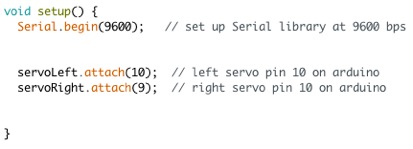
Figure 3: Setup Function

Next we are going to skip over the main loop for now to talk about the different subroutines we will be using. For our mission, each ankle will have to do 4 movements; turn 90 degrees left, turn 90 degrees right, turn 180 degrees left, turn 180 degrees right. Depending on which leg is turning, these will be in a different order. For example, lets say the robot is standing on its left foot and wants to make a simple left turn. The servo will have to turn left 90 degrees, then turn right 90 degrees once that leg is off the ground to get back to its original position. If we started on the right foot, the servo would have to turn right 90 degrees first, then left 90 degrees the next time it is off the ground to return to its original position. The robot would also have to do the same exact series of movements to turn around except the servo will be turning 180 degrees instead of 90. In order to implement these movements, we will have to write one subroutine for each movement.

Since there are four movements for each leg, that would translate to eight subroutines total. These subroutines include; LeftTurnLeft, LeftReturnLeft, LeftTurnAround, LeftReturnAround, RightTurnRight, RightReturnRight, RightTurnAround and RightReturnAround. Each subroutine does exactly what the name implies.

Looking in to the left turning subroutine shown below, I will talk about the methods I used to accomplish the task.

Figure 4: LeftTurnLeft Subroutine

The implementation was simple. Using a for loop and the servo.write function, the servo moves one degree with a specified delay time in between, which determines the overall speed. For this subroutine I used a delay time of 20 milliseconds so the total time would be just 0.020*90 = 1.8 seconds to move from 0 degrees to 90 degrees.

Once I had one subroutine working, I was able to use the first one as a template for the rest. The whole list is shown below.


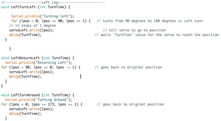
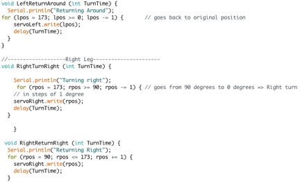
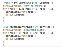
Figure 5: List of Subroutines

After creating our subroutines, we are finally able to jump into our main loop where each of the servo subroutines will be called. For the final mission, the BiPed will be commanded via Bluetooth. But for testing purposes only, I will be using the serial monitor to input commands. There are many ways to do this, but for simplicity I will be using the switch-case method, where certain letters will be translated into certain functions. The loop is shown below.
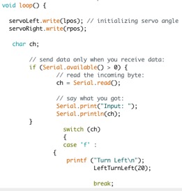
Figure 6: Main Loop

From the lower half of the screenshot you can see case ‘f ‘: LeftTurnLeft. This means that when ‘f ’ is typed into the serial command window, it will call the LeftTurnLeft subroutine with a delay time of 20 milliseconds. I cut off the rest of the cases but it continues to list every correlation between input letters and their subroutine.

Finally, after creating all of the subroutines and command inputs, it was time to test it out. Using the same connections that were laid out before, with the control pin connected to digital pin 9, I sent the commands through the serial monitor and verified the result.

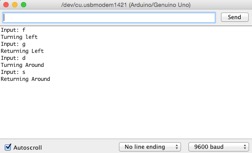
Figure 7: Serial Monitor

It works! Not only did the servo follow the command, but the result is also displayed on the window. To test the right leg I just moved the control pin from digital pin 10 to digital pin 9 on the Arduino.

Conclusion

We were able to test all sorts of turning and verify that for our needs of the game and our mission objectives, we will be able to achieve mission success.

Spring 2017 Velociraptor: Robot Assembly Process

Authors

By: Andrea Lamore (Manufacturing)
– Assembly Process
Edited & Approved By: Jesus Enriquez (Project Manager)
– Introduction & Conclusion

Table of Contents

Introduction

Before going into Critical Design Review, our team had to assemble the Velociraptor in order to have it Demo ready. Prior to PDR, we had a design in mind which was modeled on SolidWorks which continued to change as we approached CDR and we went through the engineering design process making iterative changes through the weeks between the two presentations. This post covers some of the thinking and planning that went through our minds as the Velociraptor was being assembled throughout the weeks.

Assembly Process

Assembling the Velociraptor resulted in minor changes to the original design. The legs were made up of several linkages. Screws and locknuts were used as the shaft. Lining up the linkages so that every piece was parallel with the other was key in eliminating the wobbliness of the leg and smoothing out the steps.

I decided to laser cut the flat parts to ensure the dimensions were accurate and the linkages came out smooth. The circle shaped shaft that connects to the motor needed to be re-cut so the there was a tighter fit between the motor shaft and the leg rotation shaft. The smoothness of the “step” is key in getting the velociraptor walking without falling. Below I circled the hip shaft and what part needed to be re-cut.

Note: The primary tools used were a wrench and needle nose pliers.


Figure 1: Modified Circular Shaft


The servo holder was too delicate and bulky. I ended up laser cutting a part that would replace the 3D printed servo holder. The following shows previous and new design for the servo holder.


Figure 2: Original Servo Holder Design


Figure 3: New Servo Holder Design


The hip of the velociraptor was too long and was just barely hitting the leg shaft on each rotation making the steps wobbly. I had the option of sawing the hip shorter or reprinting it and decided to reprint it. The following image shows the new hip and SolidWorks verified the new part would not hit the leg shaft.


Figure 4: SolidWorks Model of New Hip-Design Assembly


The feet were laser-cut and super-glued together using “gel” super glue. The resulting hold was very strong and in the future I will try to laser-cut as many parts as possible and super-glue them together instead of 3D printing. The spring mechanism for the foot worked as planned. A little groove was cut into the spring slot so that the spring would not easily slip out of place. The following image shows Left-leg waiting patiently while Right-leg is assembled.


Figure 5: Laser-Cut Version for Velociraptor Legs


The following 3 image demonstrate how the foot bends at the ankle using the springs:


Figure 6: New laser-cut Velociraptor Ankle/Foot Design


The head and tail radius, as well as the dummy-weights on the end were adjusted until the velociraptor could stand without tipping over. In the future, as we add the micro-controller and other components, the velociraptor’s head and tail radius as well as the angle of head and tail rotation need to be calibrated with each change in structure.

The gears for the turning mechanism worked well but were recut using thicker plastic to ensure they do not slip when the velociraptor is walking.

The u-joints were originally 3D printed but came out unusable. Lego U-joints and shafts were ordered to be used instead. They worked marvelously. The following images show the 3d printed u-Joints and the Lego u-connects.

Figure 7: Original 3D printed Universal Joints

Figure 8: Lego Universal Joints to replace original U-Joints

The leg shaft and dc motor shafts are not threaded so a screw could not be used as a cap. Instead little rubber bands were used to cap them and prevent slipping-out.

Figure 9: Rubber bands used to cap the screws

For the sake of simplifying the code to come, the group decided one DC motor would be used instead of two. The legs had to be moved 180 degrees out of phase with one another before being locked into place. It was easy to calibrate this since the shaft can only be rotated in increments of 90 degrees to ensure a proper fit.

Figure 10: DC Motor Shaft Design

Figure 10: Velociraptor Assembly before CDR

Conclusion

During hardware design changes, we noticed that the original design was a lot more bulky, making it over all heavier and it also became more challenging to get the robot to walk, let alone standing. Our Manufacturing continued to strip parts away and simplified the design to give it a cleaner and tighter look which also allowed the robot to move more functionally. The final design can be reference to in the final blog post for the Spring 2017 Velociraptor.

References

  1. https://www.amazon.com/Technic-U-Joint-Mindstorms-Universal-Joint/dp/B01IKRCU7K/ref=sr_1_1?s=toys-and-games&ie=UTF8&qid=1492407338&sr=1-1&keywords=lego+u+joint
  2. https://www.amazon.com/gp/product/B00OT8QWLK/ref=oh_aui_detailpage_o00_s00?ie=UTF8&th=1
  3. https://www.123rf.com/photo_19111999_assembling-a-robot.html


Pick and Place – SOLENOID VALVE DESIGN AND CONTROL

By: Tyler Jones (Manufacturing) and Kevin Ruelas (Electronics)

                                                                            Figure 1 

                                                                       Figure 2

The above Figure 1 and Figure 2 schematics show the solenoid circuit simulated in LTSpice. The circuit on the left shows that when the arduino pin is set to high the circuit turns on allowing the current to flow through drain and source to the solenoid valve. The circuit on the right shows that when the arduino is set to low, there is no current flowing through the drain and source to the solenoid.

This creates an electronically controlled switch, and can be programmed to turn the pump on when picking a part, and off when placing a part. This is vital to the pick and place control system because it needs to be able to switch on using power from the Me Adapter board of +5V, to control a larger voltage of +11.7V from the Me Uno header pins. The IRF 530 MOSFET switches the gate voltage of +4.7V to the source drain voltage of +11.7V This voltage can is now large enough to drive a current to the solenoid and turn it on and off.n The diode is placed from power across to the solenoid as a flyback diode. This means that the cathode points toward the positive power rail. The diode is a 1N4001 1 amp diode. The sole purpose of the flyback diode is to prevent the unwanted voltage spike that can be created in the inductive solenoid coil. The IRF 530 MOSFET was chosen based on the datasheet values that it can handle lower logic level voltages to turn on, and can channel about 20V across the source drain channel. This is more than enough to handle our 12V source drain voltage The +4.7V control voltage from the arduino is programmed to correspond to the following values.

CODE SENT $9 (GCODE) $10 (GCODE)
ARDUINO PIN +4.7V (HIGH) +0V (LOW)
IRF 530 MOSFET ON OFF
SOLENOID ON OFF
SUCTION PUMP ON OFF
ACTION PICK PLACE

 The solenoid was tested using an ammeter in series with the Drain of the MOSFET and wire of the solenoid. The current draw shown in Figure 3 through the MOSFET into the load was about 410mA. The turn on current needed to excite the coil in the solenoid was found to be about 310mA. This means that the solenoids resistance value can be modeled most accurately as an inductive coil load in series with a resistive load. The total resistance of the solenoid based on current draw was an operating range of about 24-35 ohms. The circuit works as designed and tested.

                                                                Figure 3

The tested circuit shown above was translated into a custom soldered PCB, in order to have the wires and components secured to a fixed location within the electronics housing. The PCB board will be mounted on standoffs inside the electronics housing.

Pick and Place – 12 Servo Mount & Tape Feeder System

By: Tyler Jones (Manufacturing) and Belinda Vivas (Project Manager)


Figure 1

In order for the pick and place machine to be able to complete one board, it must be able to pick and place many different devices for a whole board. It must be able to pick and place capacitors, and resistors of varying sizes 0402, 0603, and larger. For the purpose of the 3DoT board the components must be 0603 sized. The parts are dispensed either using the mounted reels, or the individual manually feed part tape. In order for the tape to advance the parts into the reel feeder system uses servos to run and pull the plastic cover from the SMT part tape.

Directions on how to correctly set up the tape is contained in the instruction manual. The 12 servos are mounted on an equally spaced servo mount shown in Figure 1. Additionally two sides must be created to create a “U” shaped servo mount. Shown below are the aluminium side pieces in Figure 2.

Figure 2

 Regardless of whether the user chooses to use the reels or the individual manually cut strips, the servos must advance the tape and be able to not only collect the protective outer tape film that encloses the parts, but also move the second part into the same position as the first part was in, after the first part has been placed.
Fabrication of the servo mount must incorporate 12 or more servos to be mounted on to a platform above the surface so that they can be programmed and calibrated to turn a certain distance that is calculated to move the second part forward to the same position. The servos are equally spaced in 1 inch intervals. It is important that the servos are positioned at the same distance from the base of the feeder trays. This is to ensure that the individual calibration of each servo is relatively in the same range of motion for turning, and that the force of tension on the tape is relatively similar. This can be seen in Figure 3 below.

Figure 3

The entire platform must be mounted on to two legs that support the servo platform. This is shown in Figure 4.

Figure 4

The servo platform and two sides had to be cut from 6061 0.125 inch aluminium. The aluminium was donated by the SAE. The aluminium was cut using a programmable plasma cutter. The plasma cutter utilizes a DXF file in order to create cutting lines. The part was created in SOLIDWORKS. The part was then converted to a DXF file in SOLIDWORKS. These are shown in Figure 5 and Figure 6 below.

Figure 5


Figure 6

The servo mount was drilled in twenty four locations with a drill bit that can accept M3 sized bolts. The servo mount was then assembled using very small M3 sized bolts. The bolts. were fitted with M3 sized nuts, and washers. The servo platform was welded to the two sides using a TIG welder system in order to join aluminium. The welding is shown below in Figure 7 and Figure 8.

Figure 7

Figure 8

After the full assembly has been welded together, and the holes were drilled, now the servo holder can be mounted. It is important to bolt the entire platform tightly to the legs which are bolted to the tape feeder platforms. The servo platform must be placed on the legs at a 45 degree angle. This helps to create a optimal pulling force of the outer tape. The completed servo mount is shown in Figure 9 and Figure 10. The servo motors come with circular discs that attach to the shafts of the motors. Some gorilla epoxy was applied to standard sewing spools shown in Figure 9. The spools are then fitted onto the servos and can now function as a tape cover collector, and as a way to force the tape onto the aluminium table. Information and instructions on how to force the tape onto the table is contained in the instruction manual, as well as the Feeder Tray post.

Figure 9

Figure 10

Spring 2017 BiPed – BiPed Prototype/Walking Experiment

By: Alexander Clavel (Project Manager)

Approved by: Alexander Clavel (Project Manager)

Table of Contents

Introduction

The BiPed projects goal is to be able to create a walking bipedal robot that is able to perform static walking. The definition of static walking is walking that remains constantly balanced throughout the robots entire walk. In theory, when the power to the robot is cut off, the BiPed should stay standing and balanced. This is one of our main requirements. This blog post shows the process of building one of the prototypes.

Design/Construction

The overall construction which included buying all the parts and materials and then assembling them together took a little less than a day. We decided to go with a design that was found through reserach on youtube of walking bipeds. We were looking to find something simplistic as to be able to stay light on the material as well as the power draw on the electrical components. The BiPed we based this prototype off can be found here in a video. In the video, the biped uses a straight leg with no linkage and uses circular motion to walk forward. It is also a very small design that reaches a little under 20 centimeters in height which is something we would like to incorporate in ours.

Gear Box

Figure 1

Figure 2

This was the first attempt at using a gear/pulley combination to drive the robot. The white round gears on the outside of the wood area in figure 1 show the rotational movement that the legs would be taking during the walking motion and the actual legs would be connected to the metal pegs sticking out. The rubberband in the pulley in figure 1 would wrap up to the pulley that is attached to the motor in figure 2. I tried using a 1 to 1 ratio for the pulley on the shaft to the pulley that will drive the 2 gears next to it. From reasearch done and experience with cars, I learned that using a smaller radius for the driver to a larger radius produces more torque, but less speed. For our requirements we will be needing that torque to be able to drive the robot, but we will also need to keep it fast enough to pass our speed requirement. From this reasoning I tried a 2 to 1 or 3 to 1 for the purpose of testing the walking motion. The two additional bevel gears in figure 2 were to work towards a solution for the balancing problem, but it was never completely finished due the professor not liking the design of our feet (which overlapped each other) so the design was to be changed anyways.

Leg Design/Movement

Figure 3

As stated before, there is a single wooden board for the legs that use a rotational motion for the legs. Figure 3 shows a side view of the gear box where the legs would be attached. The bottom of the robot is to the right of the image. This being just a test, I placed the pegs very close to the shaft because I just wanted to at least see if it would rotate. The final product would have to have a larger radius from peg to shaft so that the robot will be able to get a decent distance with each step. Again our design was kicked back because the feet  that were attached were overlapping to account for the balancing. Without the overlapping feet, the balancing mechanism at the top of the robot would have had to be completed.

Conclusion

Figure 4

Figure 4 shows the entire main body of the biped attached. Again the rubberband is connected from the pulley in the gearbox to the pulley driver connected to the motor. The legs were not added to the image, but again, they are connected to the metal pegs sticking out on the sides. To restate it, the gear at the top of the robot is vestigal at this point and doesn’t serve a purpose for this prototype but should play a bigger part in the final product. When completely assembled, the robot shows that it does indeed give a clean walking motion while being held in the air. When placed on the ground the robot does “walk”, but it was a very rough, sloppy, and unbalanced motion. As it moves forward it does wobble side to side to a large degree, but at a very slow pace. Concluding comments would be that:

  • It does perform a walking motion
  • It does not stay balanced without the overlapping feet unless a balancing mechanism can be created
  • The walking speed is very slow.

There will need to be more adjustments to the prototype for application on the final product.

Referrences

  1. http://www.blocklayer.com/pulley-belteng.aspx
  2. http://tech.txdi.org/gearsandpulleys
  3. https://www.youtube.com/watch?v=Z7N0xCDVzIA&feature=youtu.be

Sping 2017- SpiderBot’s Cost of Learning


By Nicholas Jacobs – Project Manager


As the Preliminary Design Review approached, Daniel, our Manufacturing Engineer, diligently modeled all of SpiderBot’s pieces in SolidWorks. SpiderBot’s design, originally found at Instructables. com, came with .dwg CAD files that had to be converted into .dfx files, which act as the industry standard for laser printing.  This conversion unknowingly created a very expensive problem I’ll talk about shortly. When it came time to print, we erred on the side of caution choosing to construct SpiderBot using a mix of 1/4 inch and 1/8 inch acrylic thicknesses. Excited for being one for being one of the first groups to have a design ready for print, I enthusiastically coordinated a meet-up with the Shop Foreman at CSULB’s Design Center and sent Daniel on his way to print. Not knowing what to expect, Daniel meets up with Foreman and learns that printing consists of $5 upfront and $1 per minute thereafter. Agreeing to this, Daniel begins to print. Remember that expensive problem I mention above? Well 45 minutes later, our parts are still printing-long story short, we spent $89 dollars on our first print for SpiderBot version 1. After talking to Daniel, we had no idea as to what caused this or how to fix it. On the bright side, all our parts were ready to be assembled, but at that point 45% of our $200 budget had been consumed.


Daniel began to scour for answers, not finding anything explicit, he did notice after the conversion process, any part that had a curve or bend was altered- now consisting of what he called ‘infinitesimal’ line segments instead of one smooth curve to make its shape. So when it came time to cut, the laser cutter was literally cutting each ‘infinitesimal’ line segment, hence the super long cut time.


Infinitesimal lines that increase print time.

Leg design with regular curves – faster print time.


We never found a quick fix for a smoother file conversion, Daniel decided to remake each part by hand ( in SolidWorks) to ensure that there were no more ‘infinitesimal’ to hamper our cut time. When talking about this problem during one of our weekly meetings, Daniel did suggest that follow-on semesters take a screenshot of the desired part, import into SolidWorks, and suggests using the ‘Trace tool’ in SolidWorks .


Accepting our losses, we moved ahead assembling SpiderBot while also conducting trade-off studies to determine what DC motors should drive our walking mechanism. At the time, I had two GM3 DC motors laying around from a previous project, and we decided to use in the meantime. Once assembly was complete, we tested our new design, by applying a 9 volt battery to both of the leg motors…it walked-just not consistently. This was mainly due to SpiderBot’s plus size weight of 842 grams, which is including two 31g GM3 DC motors. Hats off to the mail room located within the shipping and receiving building across the street from ECS building for weighing both builds of SpiderBot.  After presenting our preliminary design to the class, the customer stated that our design is too big and that we need to downsize.


build_1 – look at nuts and bolts for size comparison.


Reducing the size of SpiderBot isn’t as tedious as you may think. Daniel again found a ‘scale’  tool (mold tools> scale OR insert>features> scale)  within SolidWorks that allows you to expediently reduce/enlarge the size of each part by a certain factor. With the infinitesimal lines gone, the creation of a smaller more streamlined design, and all parts planned be recut using 1/8 inch acrylic, we rush to print build 2 eager to see our reduction in weight and size.


$25. That is all our 2nd cut cost to complete. That included $5 upfront cost and then 11 minutes ($11) to cut, plus $9 for a sheet of 1/8 inch acrylic. The cost breakdown is as follows:

$89 + $20 ( materials) = $109 for build_1

$11 + $5 + $9 = $25 for build_2

The corrections made from build_1 to build_2 led to a 77% reduction in price. However, the best is yet to come- our desired mass. After all pieces were cut Daniel quickly assembled SpiderBot build_2, he used a Parallax proto-board from EE 370 Lab to act as a power source to drive both motors.

build_2 – notice how much larger the nuts and bolts appear


With GM3 motors attached, we took build_2 and returned to the post office to check the new weight.

much better…for build_2!!


A breakdown of our mass:

780g + 31g(2) = 842 g build_1

385g (includes GM3s) build_2

Build_2 was a 54% reduction in mass!!

With this significant weight reduction, SpiderBot walks consistently, smoothly and appears to have little to no friction points.

As of 19 April 2017, with the 3Dot board, camera (smart phone – 178g), prototype grappling system, we’re approaching 750 grams. If we would have stuck with Build_1 we would have approached and most likely exceeded 1Kg. During our verification and validation stages over the next two weeks, the SpiderBot team will continue to look for ways to reduce our weight to ensure the best most efficient design.