S17 Preliminary Project Plan: Prosthetic Hand
Preliminary Project Plan with initial Work Breakdown Structure, Top Level Schedule, System and Subsystem level tasks, the Burndown, and System Resource Reports and the Cost Report.
Preliminary Project Plan with initial Work Breakdown Structure, Top Level Schedule, System and Subsystem level tasks, the Burndown, and System Resource Reports and the Cost Report.
Nicholas Jacobs – Project Manager
Jeff Fuentes – Systems Engineer
Shaun Pasoz – Electronic and Control Engineer
Daniel Matias – Manufacturing Engineer
Table of Contents
By Nicholas Jacobs – Project Manager
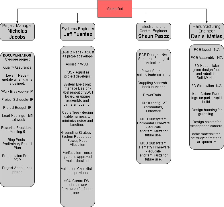
The following is SpiderBot’s Work Breakdown Structure. It gives a glimpse of the responsibilites of each team member as the semester progresses. This document will be updated weekly to reflect new and completed tasks.
By Nicholas Jacobs – Project Manager
The above chart describes high-level tasks that need to be completed. This breaks down tasks by engineer. As tasks arise they will be added and updated in follow on blog posts.
By Nicholas Jacobs – Project Manager
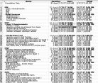
Above is a brief description of our system and subsystem level task. These will changes as the semester progresses.
By Nicholas Jacobs – Project Manager
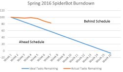
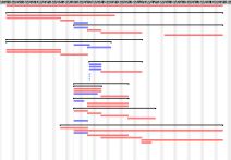
The above Burndown is a visual aid to represent reamaining tasks to complete SpiderBot. This Burndown will be updated weekly as tasks are completed.
By Jeff Fuetes – System Engineer
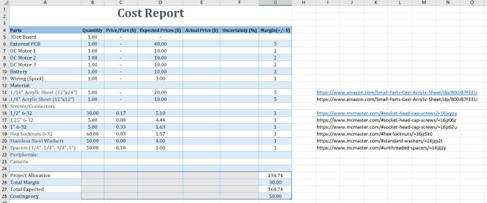
The above chart reflects estimated cost of parts, CNC machine time, and material. This is a chart that will change with the customer demands. Costs do not include shipping costs.

Project Team:
Jesus Enriquez (Project Manager)
Oscar Ramirez (Mission, Systems, & Test)
Mohammar Mairena (Electronics & Control)
Andrea Lamore (Manufacturing)
Table of Contents
By Jesus Enriquez (Project Manager)
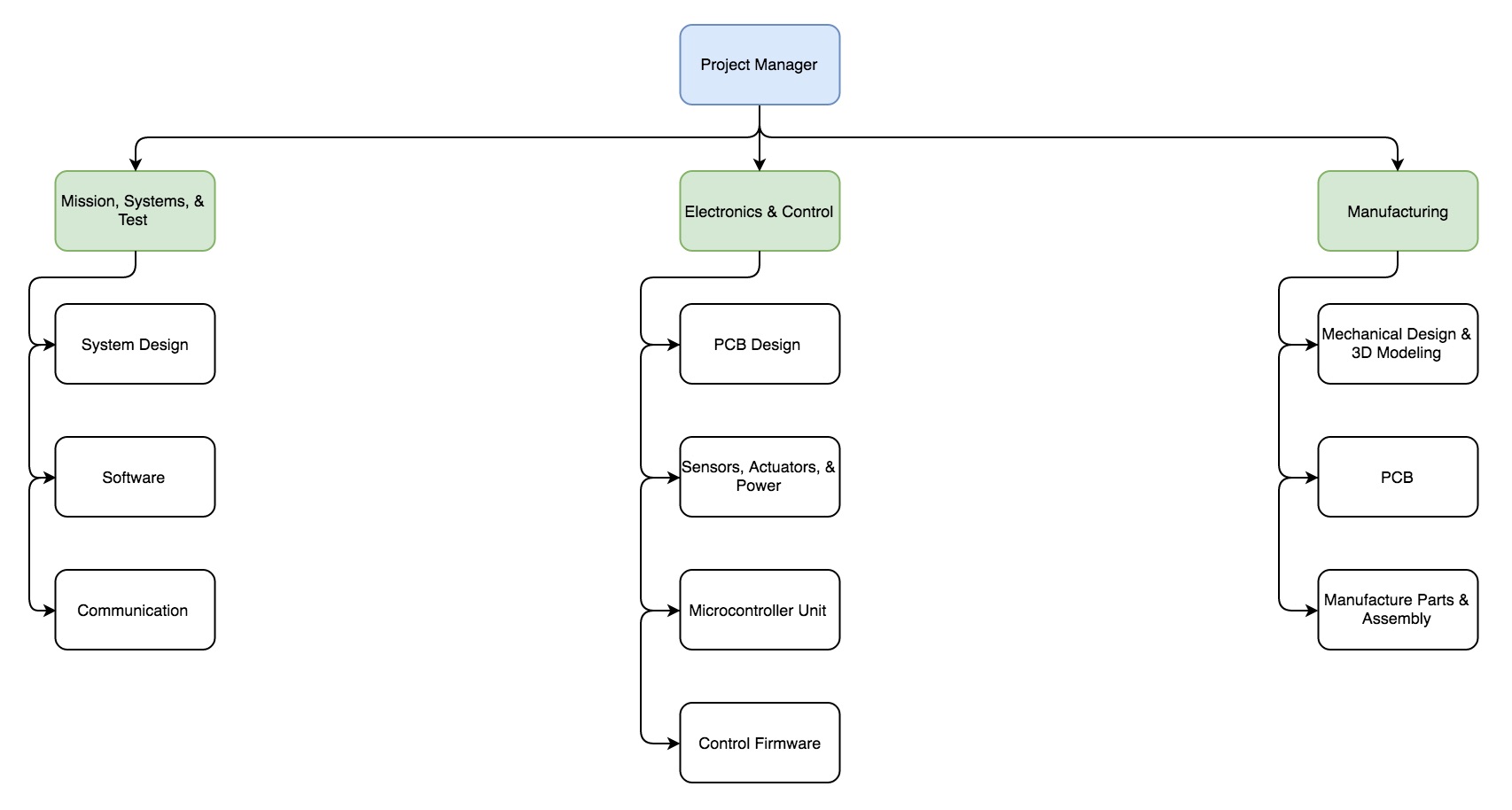
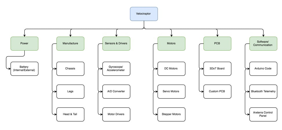
The figure below shows the Work Breakdown Structure for the Velociraptor project splitting the responsibilities and tasks of each member within their respective division. The structure was developed through research and development of Level 1 Requirements that were agreed upon between the Customer and Project Management team. Specific tasks were assigned as solutions to complete the mission profile of the project as explained in the Preliminary Design Document.
By Jesus Enriquez (Project Manager)
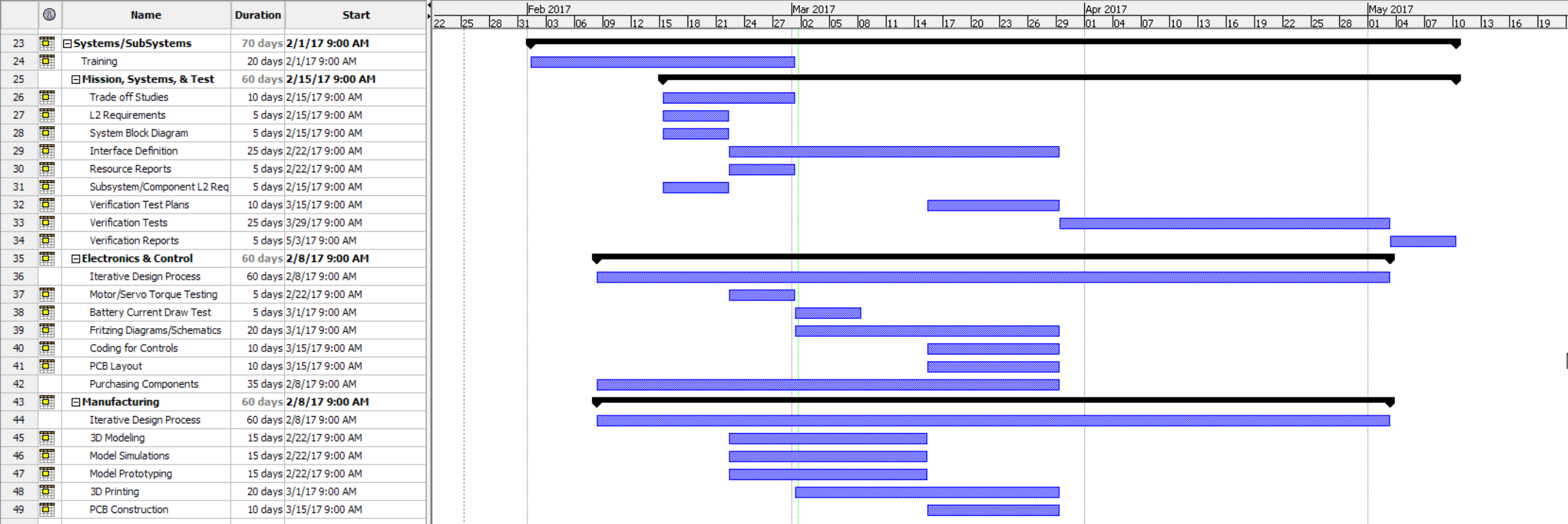
The following figure below show the project timeline from a Top Level Project and System/Subsystem Level perspective. The tasks within the Top Level Perspective derive from the Level 1 requirements as agreed upon between the Customer and the Project Management team. The top level consists of 4 main components: Planning, Design, Assembly, Project Launch. These different components have specific tasks that are critical paths to one another throughout the semester in order to reach project completion.
The system/subsystem level project schedule is structured to compliment the Product Breakdown Structure and the tasks assigned to each respective division. These tasks are split amongst the systems and subsystems engineers as shown in the figure which include MST, E&C, and Manufacturing.

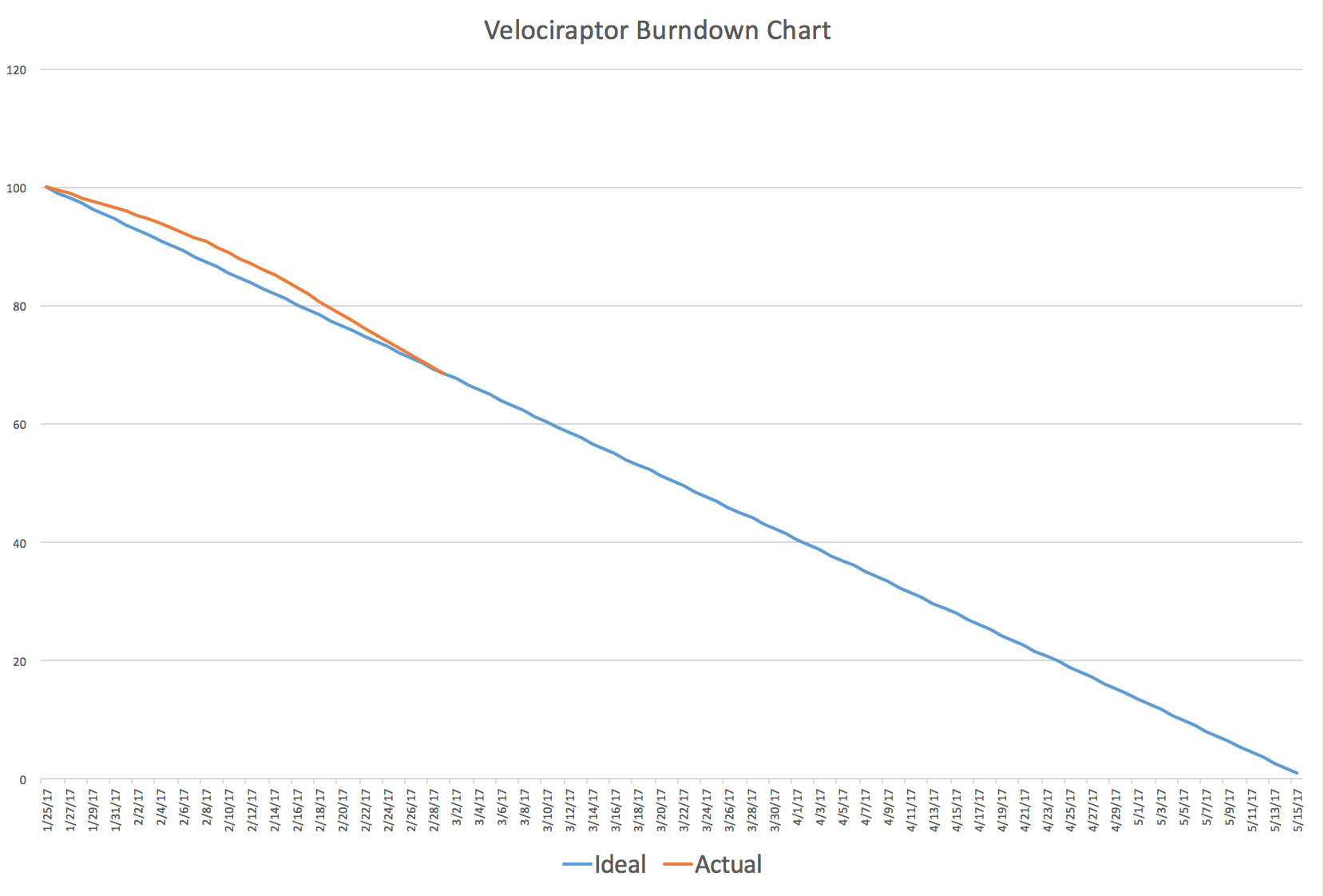
The figure below shows the burn down report graphically representing metrics of the project and how well our project team is meeting project deadlines. Our project was graphed in percentage terms over the course of 15 weeks (full semester). As detailed in the figure, the “Orange” data shows us the actual work or state of the project completed, whereas the “blue” data shows us the ideal task completion our project should follow. This Burn Down report follows the task as given in the Gant Chart shown in the Project Schedule.
By Oscar Ramirez (Mission, Systems, & Test)
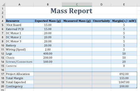
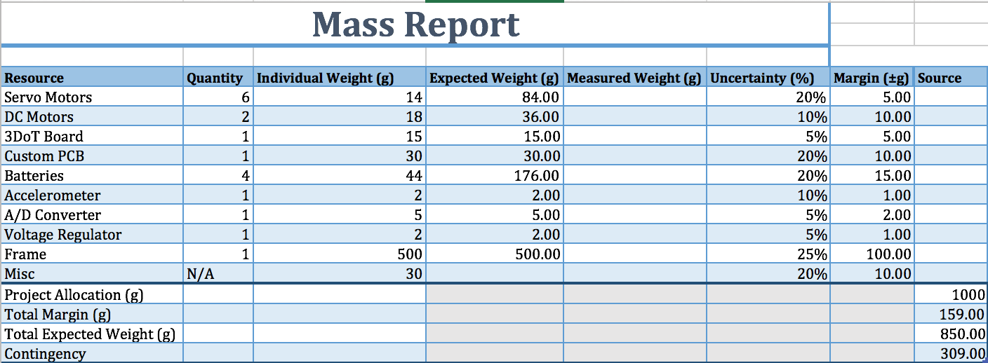
Mass Report
The goal for the mass of the velociraptor was to be able to carry a sufficient load (secret weapon) while continuing to operate normally. The mass of the robot should not affect basic functions such as walking or turning. The mass ideally should be less than one kilogram since power consumption from our motors will begin to become an issue. The total expected weight of the robot is 850 grams and falls below one kilogram, which should be sufficient enough for our motors to handle. The aluminum frame while sturdy is a lightweight metal with a low density and weighs less than polylactic acid (3d printed plastic).
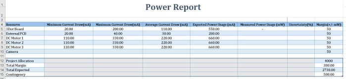
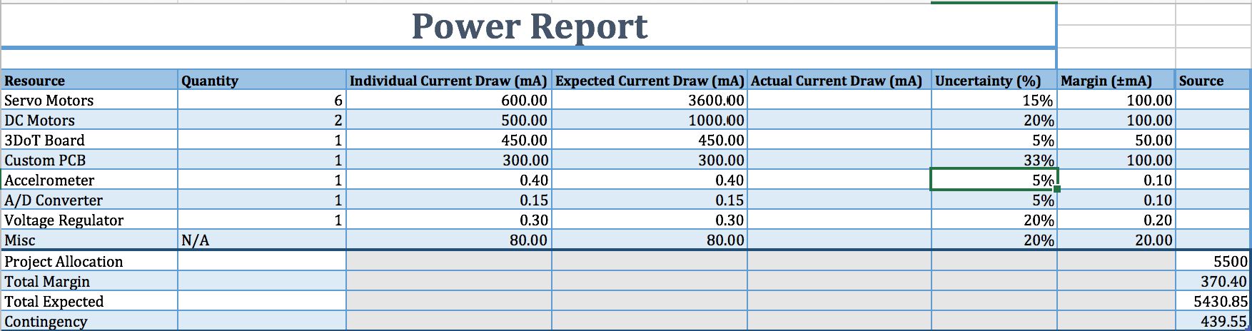
Power Report
The amount of power that will be consumed by the velociraptor will ideally less than 5500mA. For this we will need four batteries that can provide this much or greater combined current. The majority of the power being consumed is from the Servo and DC motors but the 3DoT board and the custom PCB will also have an expected current draw of 750mA. The rest of the current drawn from the robot is almost negligible compared to the motors and boards but is still accounted for. Finding the type of batteries that can supply this much combined current should not be too much of an issue since most batteries that can power our robot typically output more than 1500mAh.
By Oscar Ramirez (Mission, Systems, & Test)
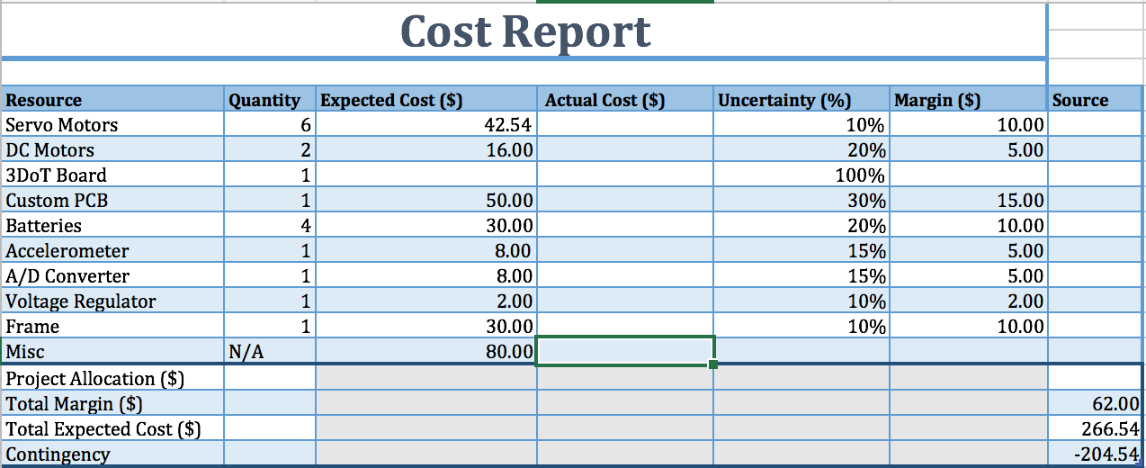
Cost Report
The overall cost of the project should be $266.54 therefore a budget of $300 should cover all expenses and uncertainties. The highest factors contributing to this cost are the motors and custom PCB, which should take a considerable amount from the budget since they are the main components. There is some uncertainty with the custom PCB cost since we have gotten some rough quotes from different suppliers. The material should be relatively cheap since we are using aluminum but the cost to stencil the aluminum to our design is a cost that has been accounted for in the miscellaneous section of the cost report. More miscellaneous costs include wire, small components, and additional parts. Overall this project could be completed with a budget of $300 but this is not accounting for the 3DoT board.
Resources:

Belinda Vivas (Project Manager)
Chastin Realubit (Mission, Systems, and Test)
Kevin Ruelas (Electronics and Control)
Tyler Jones (Manufacturing)
Table of Contents
By Belinda Vivas (Project Manager) and Chastin Realubit (Mission, Systems, and Test)
The Work Breakdown Structure (WBS) is a summarized visual representation of the divided work between the three divisions (Systems, Electronics, and Manufacturing) to successfully complete the second generation of the Pick and Place. The WBS dictates the overall project schedule for the duration of the project, 16 weeks.

Figure 1 – Work Breakdown Structure
Source Material:
http://web.csulb.edu/~hill/ee400d/Lectures/Week%2003%20Creativity/b_Requirements.pdf
By Belinda Vivas (Project Manager)
Following the defined Work Breakdown Structure, we can now present a detailed Project Schedule. This will give structure and clear direction to all divisions of the project, it presents a beginning and ending date, duration for each task, and how for certain tasks to begin the previous tasks have to be successfully completed.
By Belinda Vivas (Project Manager)
The Top Level Schedule is a detailed visual representation of a detailed project schedule. If the team or a division engineer fall behind it will affect the remaining due dates of the tasks to follow, therefore the dates will have to be revised and shorten the period of future tasks to allow for the project to be finished on the desired due date. A longer time than what is needed was allocated for the Software and Assembly Phase for when a task is running behind schedule we can take days from those items. The Top Level Schedule further shows the System/Subsystem Level Tasks. The chart below shows the detailed Top Level Schedule for the second generation of the Pick and Place.

Figure 2 – Top Level Schedule from 01/23 to 04/02

Figure 3 – Top Level Schedule from 04/02 to 05/15
By Chastin Realubit (Mission, Systems, and Test)
The Burn Down is graph representing the amount of work we have finished verses the amount of work we still need to do. We have currently finished more than 20% of the project.

Figure 4 – Product Burndown
By Chastin Realubit (Mission, Systems, and Test)
| Vacuum System Components | Preliminary Mass (g) | Uncertainty (%) | Margin (±g) | Expected Mass (g) | Actual Mass (g) |
| Stepper Motor (A-Axis) | 245.00 | 5% | 12.25 | 245.00 | 247 |
| Stepper Motor (Z-Axis) | 245.00 | 5% | 12.25 | 245.00 | 246 |
| Vacuum Nozzle | 40.00 | 5% | 2 | 42.80 | TBA |
| Z-Axis Actuator | 292.00 | 5% | 14.6 | 300 | 244.12 |
| Detection Camera | 300.00 | 5% | 15 | 312.00 | TBA |
| Project Allocation | Trade-Off Study will be obtained (Test to see when the Z-Axis can no longer pick up and item either due to vacuum strength or motor strength) | ||||
| Total Expected Mass | 1144.8 g | ||||
| Total Margin | 29.6 g | ||||
| Total Actual Mass | |||||
| Contingency | |||||
The purpose of the mass report is to ensure that the Z-Axis will be able to pick up any ICs or components that will we need to place on the 3dot board. Our design now is based on the first generation Pick and Place and will use mostly the same parts expect that we will be building on to it. We will add a camera in the Z-Axis so that the camera can be used for edge detection which will increase the accuracy of our machine. Next we will change the nozzle to one that has a smaller tip which will also increase accuracy. Using the first generation Pick and Place: Final Documentation, we were able to get the actual mass of each part except for the ones we plan on adding or changing.
The size and weight of the Pick and Place will not need any report because instead of being placed in a small cabinet in ECS316, it will have a permanent place in ET111 We will discuss this matter with the instructor and the president. Because of this the only dimensions that we need will be the workable area that the nozzle can work in inside of the aluminum table. Those dimensions were given to us based on the work area of the XY plotter, which is 12.2” X 15.35”.
| Components | Expected Current Draw (A) | Uncertainty (%) | Margin (±A) | Measured Current Draw(A) | |||||
| Stepper Motor (X-Axis) | .5 | 5% | .025 | ||||||
| Stepper Motor (Y-Axis) | .5 | 5% | .025 | ||||||
| Stepper Motor (Z-Axis) | .5 | 5% | .025 | ||||||
| Stepper Motor (A-Axis) | .5 | 5% | .025 | ||||||
| Detection Camera | .5 | 5% | .025 | ||||||
| Display Screen | .5 | 5% | .025 | ||||||
| Project Allocation | 3 A | ||||||||
| Total Expected Current | 3A | ||||||||
| Total Margin | .15 A | ||||||||
| Contingency | .15 A | ||||||||
We will be using the same electrical components powered by CSULBs power lines coming from the outlet as the first generation Pick and Place but we will be removing the Microservo and adding cameras and a screen to let the user know which component the Pick and Place in currently working on. We assume that they will all get the same amount of current. Testing needs to be done to check if true.
By Tyler Jones
The original pick and place was design and built using a reel feeder system that was proven to work with 0402 components. In the second generation of the pick and place it should have the ability to keep the reel feeder system as well as add ABS plastic trays for individual part strips to be added. This allows for the machine to still utilize the reel feeders if necessary, and to add a way to manufacture boards with many different parts using multiple ABS plastic trays for all types of IC packages and sizes. An example of the size and dimensions in inches of the plastic trays are shown below in Figure 5. Implementing two of these trays allows for 8 possible channels for the SMT part tape to be feed onto the table. This can then successfully populate the 3DoT board with enough parts and covers all possible part diversity used in the 3DoT board.
Figure 5 – Component Feeder
Another requirement to fulfill is to populate a 3DoT board which contains many different components including resistors, capacitors, and IC of different sizes. In order to successfully manufacture boards with all these components it is necessary to make the machine easy to setup and to use. It should also be able to be easily disassembled and moved. The user must be able to setup the pick and place machine and operate it in a timely manner of less than two hours. It must be able to populate a 3DoT board in a reasonable time frame of ten to sixty minutes.
In order to accomplish this task, the pick and place will incorporate organized easily configured and usable mechanical design features. A storage cabinet can be created using acrylic plastic sheet stock. This plastic can be shaped and fashioned to fit underneath seamlessly into the legs and support system. The cabinet can be mounted underneath, and will be able to house the SMT part reels, the vacuum pump, spare nozzles, SMT part strips, scissors, and solder paste, and stencils. Additionally, the legs and support system of the machine must be raised in order to meet this requirement. This includes lengthening the legs from a current height of 7 inches to a new height of 10 inches. This will allow the cabinet to be placed underneath and house the pump, and other components, without adding too much additional height, length, and width. The current pick and place is (27.6875 inches long x 15.9375 inches wide x 17.625 inches in height) (27.6875” x 15.9375” x 17.625”) It is also essential to make all housings and compartments easily and quickly able to be disassembled, and assembled. This means that the bolts must be properly tapped and dyed into the plastic material. Countersinking will need to be done as well in order to provide no stress fractures or bending of the plastic material. The plastic can be pre-ordered from Home Depot and its specifications are below in Figure 6. Purchasing two of these sheets will be necessary to create the cabinet. The used will not have to be purchased and would only total to around $15-$20 if they were to be purchased. This would bring the total to $121.76 for the machines new layout.
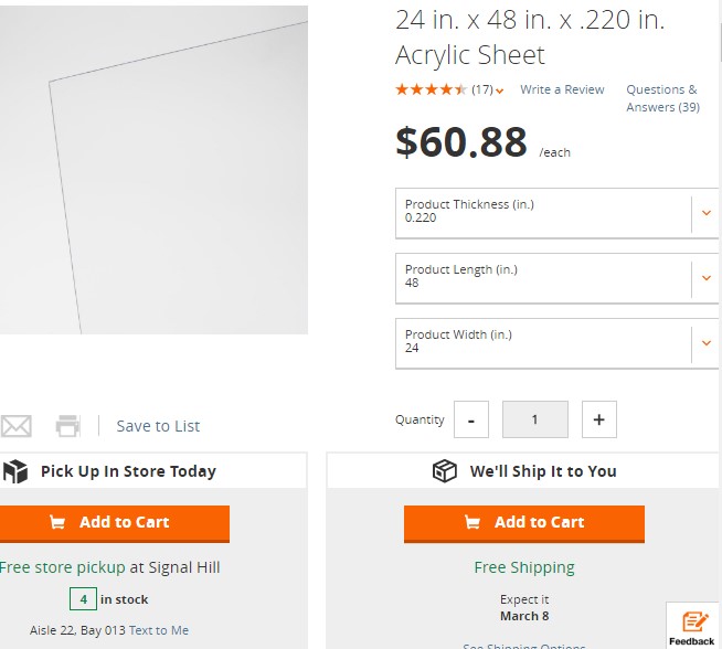
Figure 6 – Acrylic Sheet
In addition to the creation of the plastic housing, the machines dimensions were written down and noted for further design in Solid works and machining. The current wiring of the pick and place is lacking organization, and functional design. The Ethernet CAT 5 cables cables connecting to the Me Uno microcontroller are too short to fully re-program the machine to operate on every operable inch of the aluminum picking and placing surface. This would call for longer 5-foot CAT 5 RJ 25 port sized Ethernet cables. These can be found on Digi key in many lengths and styles, for roughly $5-9 The link for the cables can be found below.
http://www.digikey.com/products/en/cable-assemblies/modular
A wire mold similar to commercially available V5000 series wire mold can be manufactured using Solidworks STL files, and ABS plastic. These wire molds can be mounted in channels on the inside of the housing so that the wires are not stretched or damaged. Further Solidworks files will be generated.
A trade off study should be used to measure vibrations or disturbances at the base of machine using different methods of testing for shaking, vibrating, and shock. This is important because stability is vital in a precision robotic machine used to pick up very small components. Rubber shoes can be fitted onto the legs and tested as the machine operates for disturbances in the pick and place routine. Figure 7 shows a block of rubber that can be purchased and shaped into shoes that cover the legs of the machine. The rubber block can be purchased for $6.95 online.
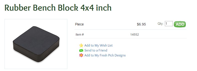
Figure 7 – Rubber Bench Block
Another trade off study should be taken in positioning the reel feeders so that the tape can freely and easily be stripped of tape and moved the same consistent distance by the micro servos motors. This will affect the height and dimensions of the plastic cabinet.
A key facet in creating the pick and place to be more user friendly is implementing a LCD and LED screen that displays instructions and live camera feed of the machines operations. These components need to be large and accessible in order for the user to view and interact with the machine. The plastic housing underneath the machine will be able to house folding or telescoping style mounts for the LCD and LED screens. This allows the screens to be tucked away without taking up unnecessary space. A trade off study can be conducted in order to find whether or not the folding or telescope system is more durable, and stable.
Inside the plastic housing design and small slide out drawer can be easily fashioned and located underneath the tape that is pulled from either the stationary trays or the current reel feeders. This cleans up the mess as the machine functions and can easily be slid out and thrown away. A force analysis should be calculated to see how much force will push back on the tape. This is critical because if the force of the tape hitting the edge of the drawer is too great it will throw off the alignment.
A rough preliminary scale model below in Figure 8 shows the relative positioning of devices, and layouts represented in this article. Further rendering will be provided in Solidworks.

Figure 8 – Rough Preliminary Draft
MECHANICAL COST PROJECTION
|
Item |
Projected Cost | Margin | Actual Cost |
| Anti-vibrational Rubber | $6.95 | 5% | |
| Acrylic Plastic Sheets | $121.76 | 5% | |
| 5’ RJ25 cables | $7.50 | 5% | |
| STL 3D prints | $15.00 | 5% | |
| Spring Loaded nozzle | $10.00 | 5% | |
| TOTAL | $162.11 | 5% |
MECHANICAL SYSTEM WEIGHT
Total system weight added to current system is 14 pounds with a %5 margin. This estimate is contingent upon design and features.
By Kevin Ruelas
Cost
2 Cameras + additional drivers ~$50 ea
LCD Screen ~$50
RJ25 Adapters/cables ~$15
All cost has a margin of 5%. When adding the cost for Manufacturing and Electronics it gives a total cost of $277.11 for the second generation of the Pick and Place.
Alexander Clavel – Project Manager
Jacob Cheney – Missions, Systems, and Tests
Abraham Falcon – Electronics and Control
Mikaela Hess – Manufacturing and Design
Phong Nguyen – Manufacturing and Design
Table of Contents
By Alexander Clavel (Project Manager)
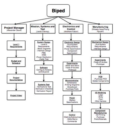
Figure 1: WBS
The Work Breakdown Structure shows the responsibilities and tasks of each member of the team. It breaks down the individual tasks and specifies exactly which division and or person it falls under. Figure 1 shows the breakdown for the BiPed Project. The structure was derived from working with the level 1 requirements previously established, the product breakdown structure, as well as the different design innovation methods we used. To set specific tasks, we had to look at what had to be done on the product as well as what we could do. These can all be referenced to the Spring 2017 Preliminary Design Document that was completed previously.
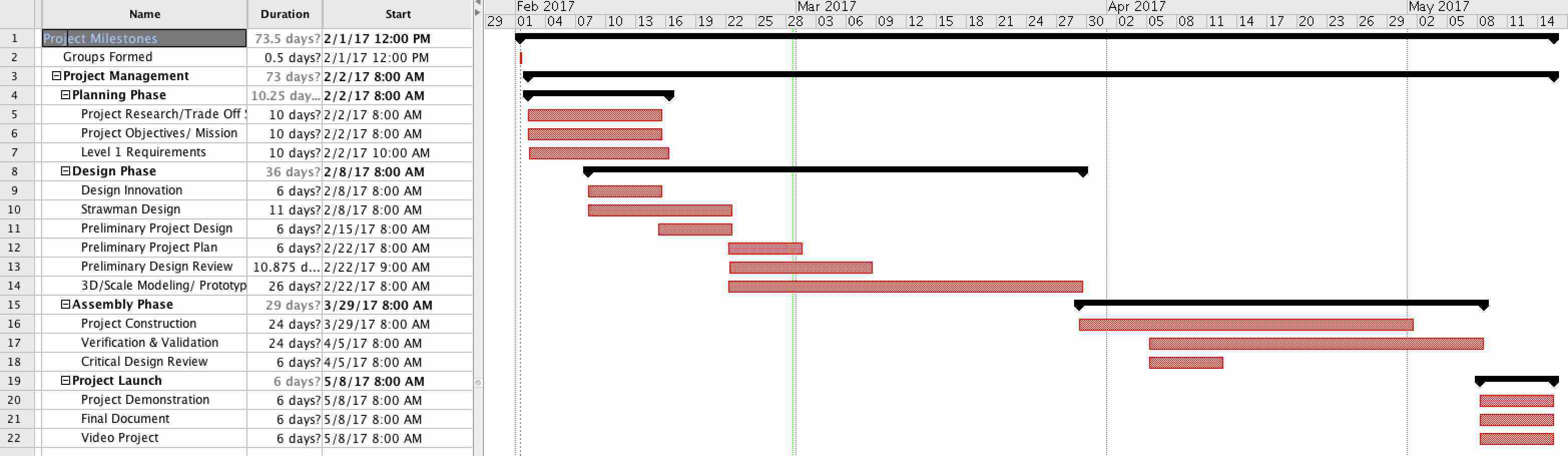
Figure 2
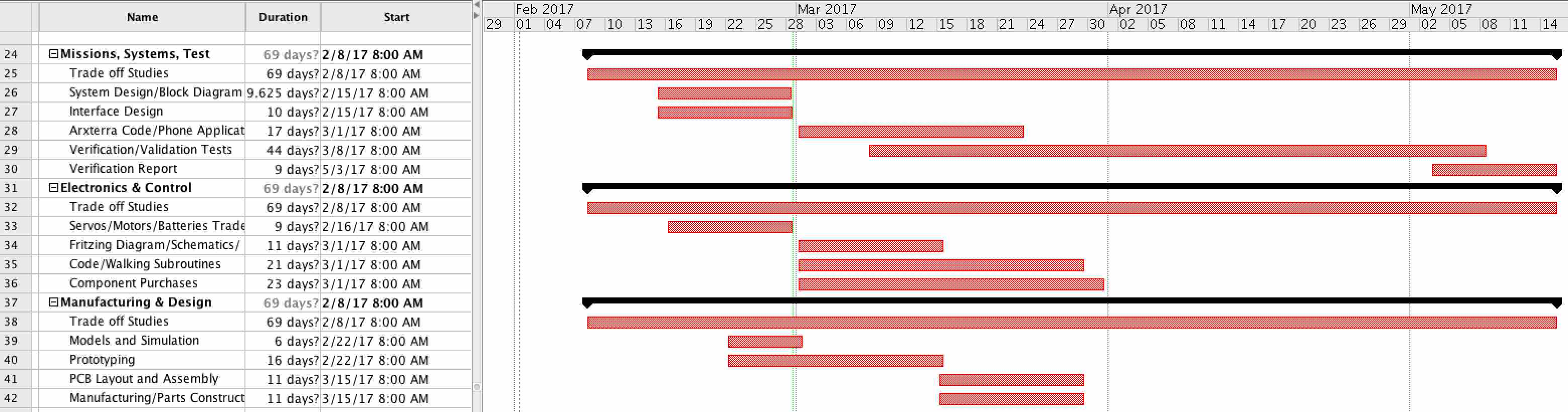
Figure 3
The project schedule gives a timeline overview of the work that needs to be done and it what time frame it needs to be completed in. Figure 2 depicts the top level schedule and the entire timeline of the BiPed project. The schedule is broken down into 4 phases which include planning, design, assembly, and project launch. The planning phase mainly consists of research required for the project as well as coming to a clear definition of the mission objectives. After the planning phase comes the designing of the BiPed. Considering that a BiPed has yet to be built using DC motors, this is proving to be a difficult part of our engineering process. Assembly comes next with project completion and project launch in conclusion.
In Figure 3 the schedule is broken down even further to specify tasks for each individual. These tasks can be traced back to the Work Breakdown Structure and include purchasing components to modeling and prototyping. Some of these jobs are ongoing throughout the project while some have specific deadlines that need to be met.
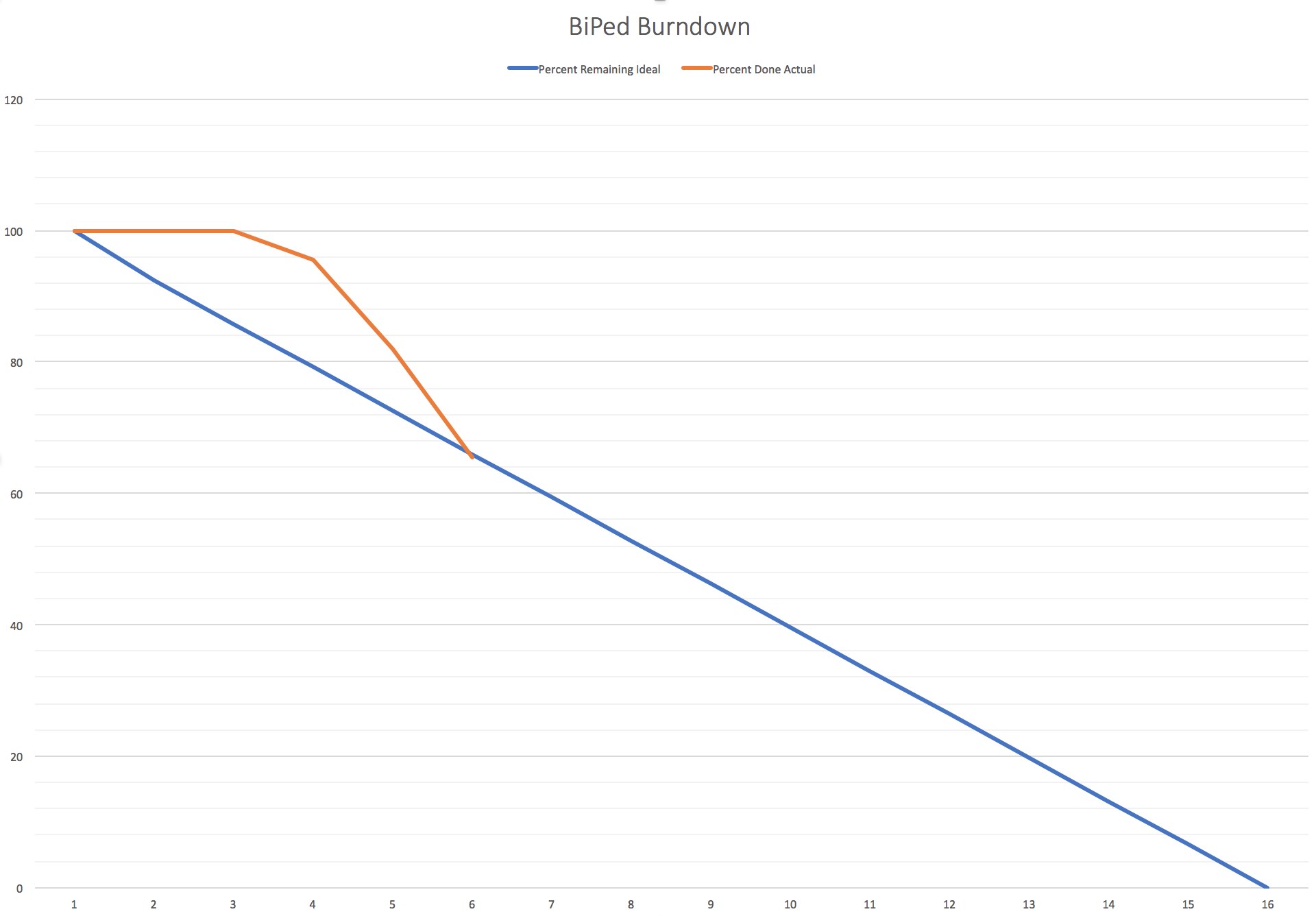
Figure 4
Figure 4 is a representation of our progress by percent. The vertical axis is a measurement of the percentage of tasks that need to be completed while the horizontal axis is the number of weeks. The blue line is the ideal percentage of work that should be done while the orange line is the percentage of work that we have actually done so far. We fell behind in the beginning in terms of tasks that need to be done but we were able to make up about 30% of the work. Most of that work is still currently in progress and not yet complete.
By Jacob Cheney (Missions, Systems, and Test)

The Mass Report shows the weight of each individual component of the system and the total of all of them combined. For some of our parts, we looked at previous semesters to get a better approximation of how much some of these components weigh. Others were found elsewhere on the web or measured by the manufacturing engineer. For the entire system, our initial calculations of the Total Expected weight came out to 392.95 grams. This lead to a Total margin of 145 grams and a Contingency of 152.05 grams.
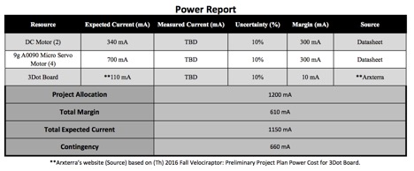
The power resource report shows the division of current throughout the Biped system. Current estimates for each component are based on their respective datasheets. Our calculations for the total expected current came out to be 1150 mA. This left us with a total margin of 610 mA and a contingency of 660 mA.
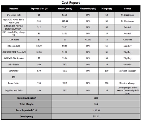
The Cost Report lists all of the parts and materials needed along with the purchase price for each. The Total Expected Cost for everything came out to $180.50 with a Total Margin of $54 and a contingency of $73.50.
Martin Diaz (Project Manager)
Adan Rodriguez (Mission Systems and Test)
Moses Holley ( Electronics and Control)
John Her ( Manufacturing – Chassis)
Edgardo (Manufacturing – Solar )
Table of Contents
By Martin Diaz (Project Manager)
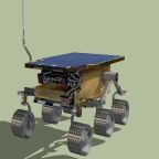
The Mini-Pathfinder will follow and support a walking robot in a to-be-negotiated Battle. The Mini-Pathfinder will autonomously follow it’s respective robot and provide video support. An operational solar polar will also be used by the Mini-Pathfinder.
http://web.csulb.edu/~hill/ee400d/S%2717%20Project%20Objectives%20and%20Mission%20Profile.pdf
By Martin Diaz (Project Manager)
By Adan Rodriguez
By Martin Diaz (Project Manager)
During our brain writing exercise we were tackling the problem of what video system will we use and how will we implement it. Several cameras were chosen and we reviewed the pros and cons of each. We choose to try our camera phone since it has capabilities of using the arxterra app and wifi capabilities to send the video. But we quickly ran into the problem of how and where will it be placed on a small chassis. A standing phone will not work because it would interfere with solar panel placement and will not be a model of the sojourner. We concluded to have a layered structure with a phone sandwiched between solar panels and the chassis. The chassis will hold the electronics and the phone will use a periscope to achieve a forward looking view from the rover.
Another possible solution that we realized during our different perspective exercise was tracking a color or led on the lead robot. This idea came up after viewing our task through nature’s point of view and imagined a mouse looking for cheese. This solution will need further research.
By Martin Diaz (PM) and Adan Rodriguez (Mission and Systems)
The WBS shows what work is assigned to each division. Mission Systems is assigned to work on arduino program and arxterra control. Manufacturing is assigned to use CAD software to design the rover. ENC is assigned to make the schematic of the custom PCB.

By Adan Rodriguez (Mission and Systems) and Martin Diaz(PM)
The PBS shows the components parts or finished product of each system. The diagram shows the components of what the chassis, 3Dot board and custom PCB, etc. will contain.
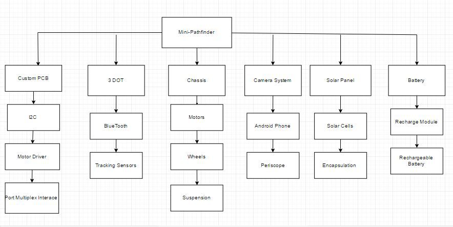
by Adan Rodriguez (Mission, Systems, and test)
We plan to use the motor controller on board the 3Dot. Due to our rover needing 6 motors a expansion board will be needed. Expansion board is going to be our custom PCB that will contain 2 more motor controllers and interface with our sensors. Bluetooth will connect to a phone for manual control. Solar panel will connect to our battery to charge.

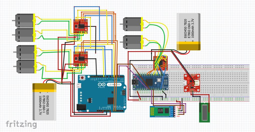
By Moses Holley (Electronics and Control)
By Moses Holley
Sources
by John Her (Manufacturing – Chassis)
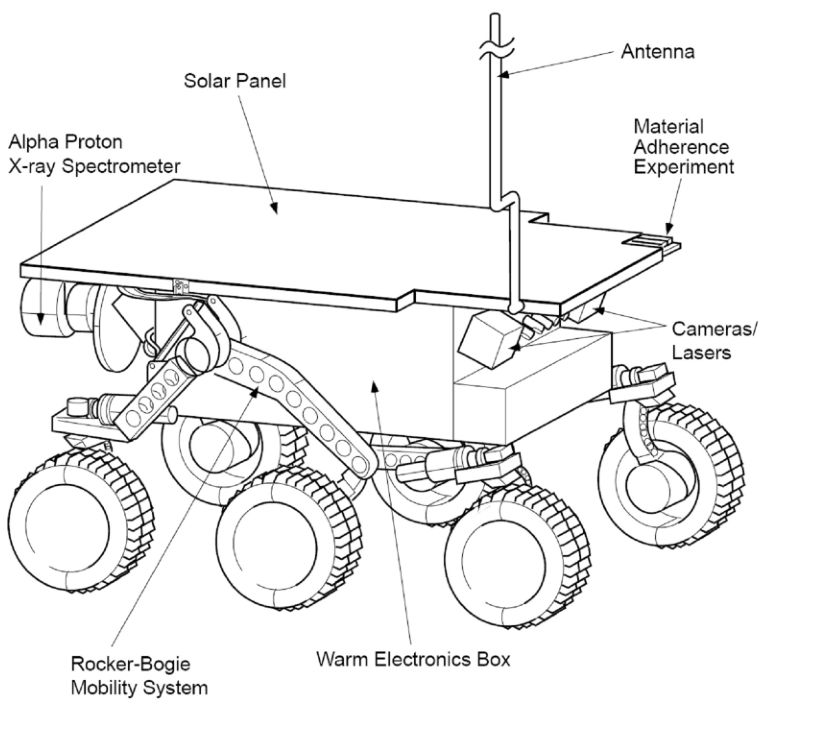
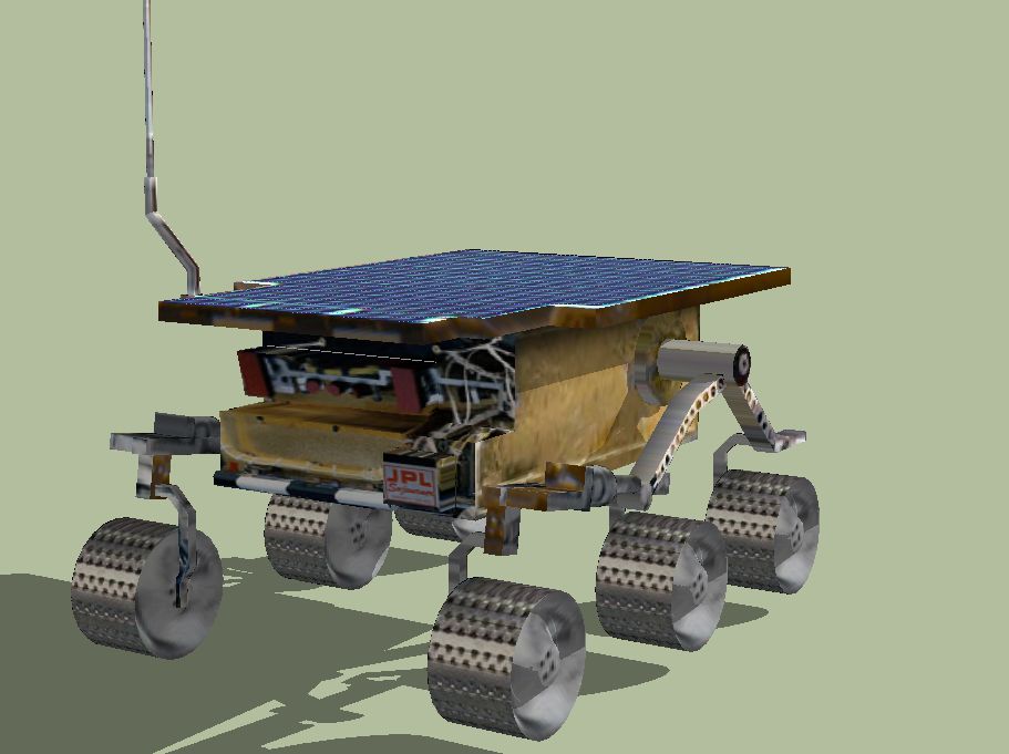
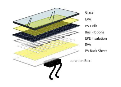
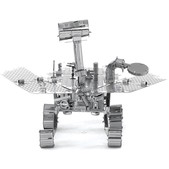
The design of our rover will follow the Sojourner rover of the Pathfinder mission. It will be a scale sized model encompassing the 3dot board within the chassis. It will continue to utilize the rocker bogie suspension and will have six motors driving the six wheels. The Sojourner rover has dimensions of 65cm(L)x48cm(W)x30cm(H) [1]. The 3dot board is 69mm(L)x35mm(W) [2] and will be enclosed within the chassis. We will also be using a smart phone as the camera system. The smart phone we will be using is the LG K10 phone which has dimensions of 146.6mm(L)x74.8mm(W)x8.8mm(H) [3]. The scale model will be as small as possible to fit the dimensions of the 3dot board. Since it has to be to scale, it can only be as small as our largest part. In this case, the phone will be our largest part. The phone will lay flat underneath the solar panel array and above the chassis containing the electronics, including the 3dot board. The Sojourner rover uses solar cells that are 4cm(L)x2cm(W) [4] that are arranged to fit in a 14(L)x18(W) array.
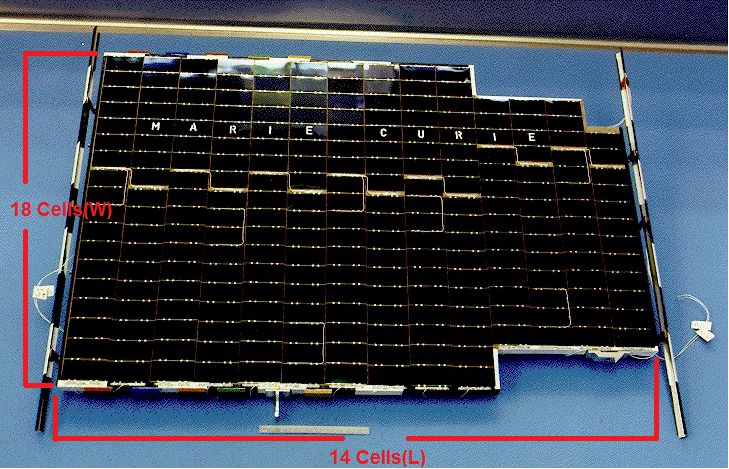
Multiplying the lengths and the widths gives the total length of 4cm/cell*14cells = 56cm and width of 2cm/cell*18cells = 36cm wide. This gives a length to width ratio (56/36=1.556) of 1:1.56. Given the length of the cell phone is 146.6mm, a scaled down solar panel of the Sojourner with the same length will have to be 94.243mm wide which is 19.443mm wider than the phone at 74.8mm. Due to the scale of our rover, an exact replica of the solar array may not be possible and may have to just be a full rectangle shape. If we are to compare the size of the solar array from the Sojourner rover and compare it to what will fit over the phone, we can obtain our scale for our rover model which is (560mm/146.6mm = 3.819) 1:3.82. Using this scale, the dimensions of our rover should be 170.16mm(L)x125.66mm(W)x78.54mm(H). Looking at the size of the wheels [5] of the Sojourner rover, we can see that it has a wheel diameter of 137mm and a width of 60mm. If we apply the scale of our rover (137mm/3.82), it gives us a wheel diameter of 35.86mm and a width (60mm/3.82) of 15.71mm. If we make the wheels have a 2mm thickness with 2mm of clearance for the motors, this gives us the option to use a motor of at most a diameter of 27.86mm since the motors will be in the wheels. To determine the size of the chassis containing the electronics, a replica paper model was printed and measured [6]. Looking at the 1:15 scale version of the model, the solar cell array was measured at 57mm(L)x43mm(W) and the chassis was measured at 39mm(L)x27mm(W)x17mm(H). The length of the chassis is 1.46 times smaller than the solar array and the width is 1.59 times smaller. When comparing the length of paper model of the chassis to the height, the height of the chassis is 2.294 times smaller. If we apply these scales to our determined solar panel size of 146.6mm(L)x94.243mm(W) then the length and width of our chassis should be 100.3mm(L)x59.18mm(W). Then comparing the length of the of this (100.3mm) to the height, 2.294 times smaller, then the height of the chassis should be 43.72mm(H). These dimensions for the chassis should provide enough clearance to contain the 3dot board.
Sources
by Egardo Villalobos (Manufacturing – Solar)
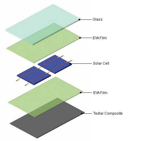
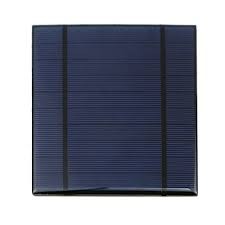
As the Manufacturing Engineer for the solar panels on the Mini Pathfinder, I am required to come up with a solution in in powering an LED on the Mini Pathfinder and, if possible, to fully power the Mini Pathfinder. Another thing we want to work on is the solar cell encapsulation because we’d like to find a way to make these cells modular so that a cell can easily be replaced.
Plexiglass provides a lightweight, anti-reflective surface and is classified as a scratch resistant surface. Although plexiglass is virtually impossible to break and scratch resistant, it can scratch much easier than glass. If this material is used to encapsulate the solar cell, we’d be able to acquire it from Home Depot or other similar store. This glass would then be used to cover the panel. To get the right shape out of the glass, we could use a dremel grinder to cut to size. The size of the glass would be the same size as the panel, which still need to be measured. The downside to using plexiglass is that the solar cell needs to be sandwiched using other materials, such as resin, which costs the same as buying one already encapsulated.
Source:
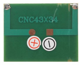
Solar cells could be bought already encapsulated with a UV resistant epoxy and are usually meant to charge phones and other toys. Each cell is independently encapsulated making it easier to remove and add new cells. These cells are also polarity based, which could require wires instead of tabbing wires, also making it easier to switch cells. Using these cells would cost about the same as buying all the materials, using the plexiglass sandwich method.
Sources:

Preliminary Design Document includes everything from the Project Objectives and Mission Profile to the Design and Unique Tasks Descriptions of the Project
Preliminary Design Document includes everything from the Project Objectives and Mission Profile to the Design and Unique Tasks Descriptions of the Project
Velociraptor Team:
Jesus Enriquez (Project Manager)
Oscar Ramirez (Mission, Systems, & Test)
Mohammar Mairena (Electronics & Control)
Andrea Lamore (Manufacturing)
Table of Contents
By Jesus Enriquez (Project Manager)
The Velociraptor Biped, inspired by that of the Titrus-III model developed by the Tokyo Institute of Technology, is to meet customer expectation through demonstration in a negotiated battle defined between the customer and the Robot Company project teams. While carrying out the mission, the Velociraptor will be operated through video support from a remote location using an assigned support vehicle from The Robot Company. The Velociraptor will be further controlled by a designated user through the Arxterra mobile application.
References:
EE 400D S’17 Project Objectives and Mission Profiles
By Jesus Enriquez (Project Manager)
References:
Fall 2016 Velociraptor (Th): Preliminary Design Document
Spring 2016 Velociraptor: Preliminary Design Document
By Oscar Ramirez (MST)
By Mohammar Mairena (E&C)
By Andrea Lamore (Manufacturing)
References:
https://www.arxterra.com/fall-2016-velociraptor-preliminary-design-documentation/ https://www.arxterra.com/3dot
https://www.arxterra.com/fall-2016-velociraptor-th-preliminary-design document/#Electronics_Subsystem_Requirements
By Jesus Enriquez (Project Manager)
After researching through the different designs of the previous generations of Velociraptor Biped Robots, it was noted that the certain types of leg mechanisms such as the Theo Jansen linkage was not appropriate to get the Robot to walk in a dynamic fashion but rather a static motion since it can only move forward and backwards rotating along a single axis. This limits the robot in terms of flexibility to move and turn in a dynamic fashion. Considering the mission of this robot per the customer’s request, it is essential that the robot have flexibility in its ability to move and turn under certain conditions. Using the creative process, our group was able to generate a few solutions.
By Oscar Ramirez (MST)
Power
The Velociraptor Biped will be powered by a portable power source that while not taking away any functionality or balance to the Biped must also be able to power the robot.
Body
The frame of the robot must have a strong material considering it will have a higher center mass when walking dynamically. The frame will consist of the head, tail, legs, and chassis. Aluminum will be ideal for this since it is not only a strong but lightweight material. Aside from the physical advantages to using aluminum the cost will also benefit the design since aluminum is going for about $30 per 4 square feet at 1.6mm thickness. This translates to a little more than one and a half kilograms of aluminum but not all of the 4 square feet sheet will be used and the frame of the robot will likely be the bulk of the mass.
Sensors and Drivers
An accelerometer will be used to help while walking to track motion and ensure that the system is not off balance. An analog to digital converter will also be used with the DC motors to track the position of the motors rotation and translate it into digital data that will be read into our microcontroller. Drivers will also be used for the DC motors since the microcontroller cannot directly control the speed of the motors.
Motors
As required by the customer, DC motor will be incorporated into our design. There will be two total DC motors that will provide motion to our Velociraptors legs and carry the majority of this load. Servo motors were used in the past but DC motors are better suited for the task since the can handle more torque. Servo motors will still be used in our design but they will be restricted to controlling the head and tail to move in sync with the center mass of the robot. Stepper motors will also be used to help provide more stability and needed torque for the legs.
PCB
There will be two PCB boards incorporated in our design. One of them will be our 3DoT board that will contain our microcontroller and control the servo motors and the other will be the main PCB board that will have all other sensors, communications systems, and drivers.
Software and Communication
The Velociraptors software will be based in C++ and written in an Arduino sketch. This sketch will control all motor functions and communicate to the Bluetooth module. The Bluetooth module will then sync with the users Android or iOS device and be controlled via the Arxterra control panel application. This application will have a GUI that will let the user perform any function of the robot such as walking, turning, and use of the on board secret weapon.
References:
http://arxterra.com/fall-2016-velociraptor-preliminary-design-documentation/
https://www.metalsdepot.com/products/alum2.phtml?page=sheet
https://www.arduino.cc/
https://www.arduino.cc/en/Main/ArduinoMotorShieldR3
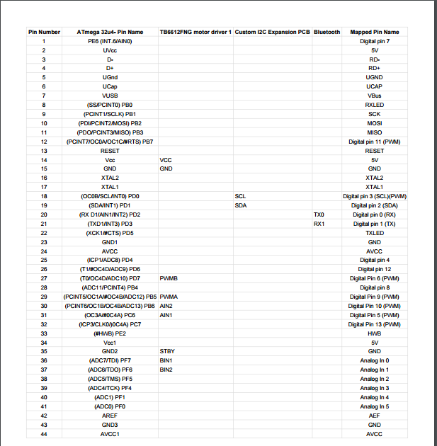
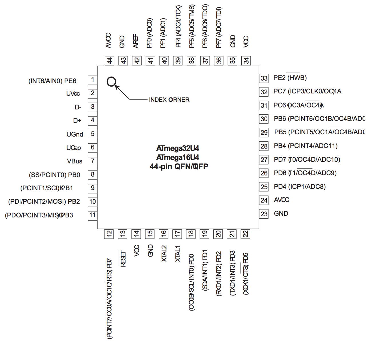
By Mohammar Mairena (Electronics & Control)

Shown above is the block diagram for the electronic design. Within the 3DoT board is the I2C interface that allows the user to add multiple devices using the SDA and SCL pins (data and clock, respectively). The block diagram highlights the importance of the micro-controller as the root of each and every device as well as the significance of the micro-controller in terms of communicating with certain devices.
By Jesus Enriquez (Project Manager)
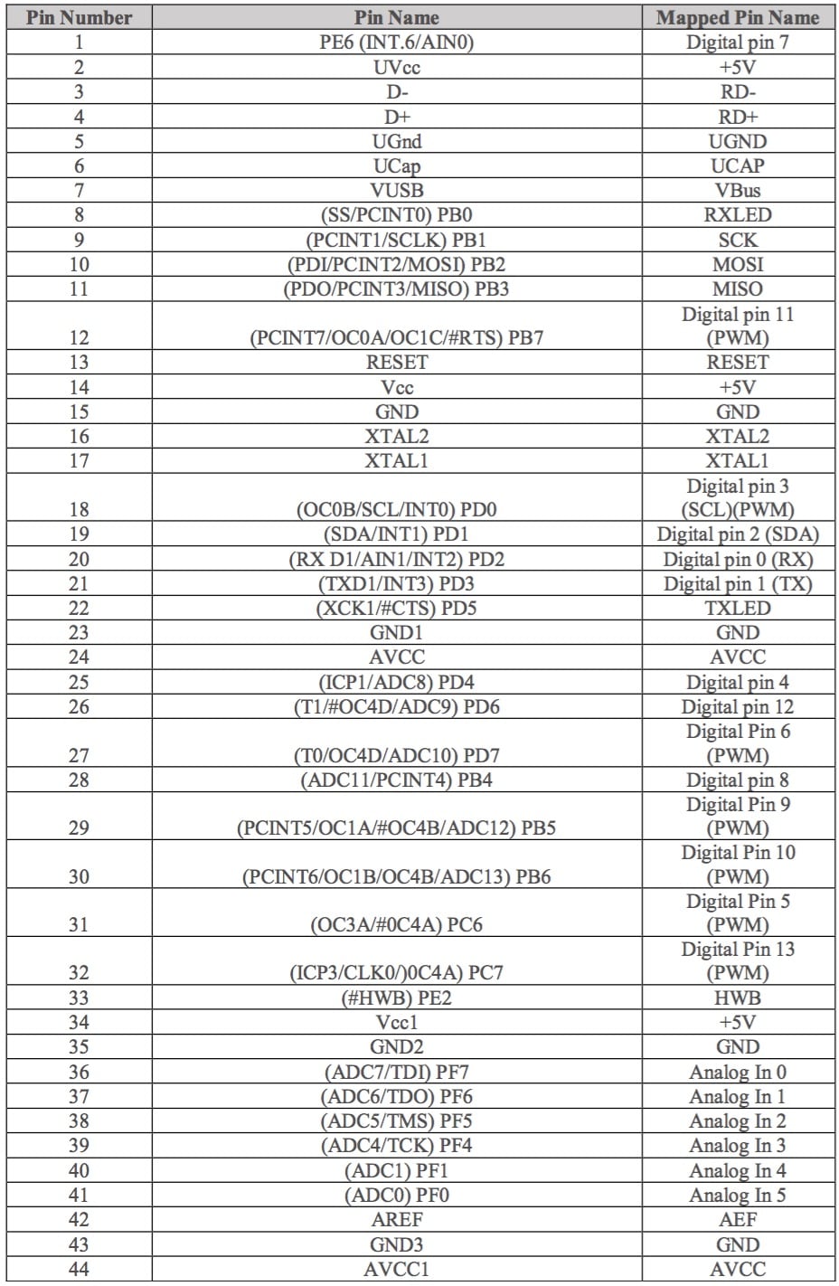
Reference:
https://www.arduino.cc/en/Hacking/PinMapping32u4
By Andrea Lamore (Manufacturing)
The velociraptor design be broken down in the following: The legs, feet, and the head-tail.
The entire design is going to be top-heavy and tall. Making the device top heavy will allow for good traction to floor and a small moment of inertia at the body so the top (the body) is more stable than the legs. The tall height in the legs makes it so there is a longer radius between the body and the feet, this also increases the moment of inertia at the body. A longer radius will give the robot more time to catch itself.

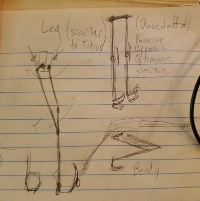
Leg Structure
The leg’s structure is going resemble that of a robot’s that is able to complete a passive dynamic walk. Without a mechanical control for preventing “bounce back” in the knee (referring to the knee bouncing back to bent after straightening), the leg design will not be able to complete a passive dynamic walk. Instead of a mechanical mechanism to prevent bounce back, there will be two motors used to control each leg – like the Titrus III design. One motor is responsible for the knee motion and the other for the swing of the hip. Using a combination of the successful passive walking robot and the Titrus III model, we will be able to create a leg that has the physical structure required for both passive and dynamic walking.
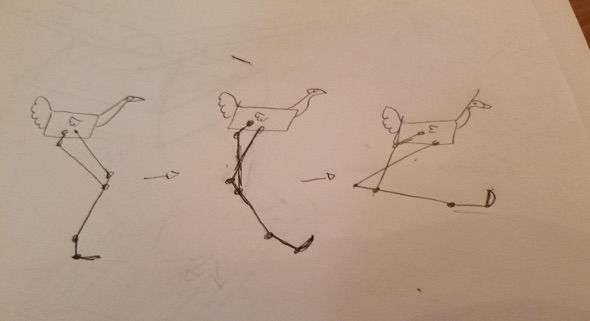
Static Walk
For the static walk the legs will be crouched by bending the knee and rotating the hip. This crouch will lower the center of mass and make the robot’s stance more stable. In the crouched position, the robot will utilize its head and tail to shift the center of mass from side to side depending on the foot that is stepping. In the crouched position the knees will move forward and the robots center of mass will be shifted, the upward motion of the head will be used to compensate for that forward motion. The tail will be capable of being used as a third leg so that the robot may utilize a very stable tripod stance.
Turning
Turning will be controlled by motor as the hips. The motors responsible for turning will be placed here in order to keep the top heavy and reduce bulk in the legs so that the legs may accelerate as fast as possible and thus catch the robot as it falls on each step faster. The hips, if viewed from the top will angle the leg away or towards being in parallel with the other leg.
Feet
The feet will be statically joined at the ankle in order to reduce the amount of motors needed. If the legs need not enter the crouching position then the static flat foot with the heal attached to the ankle would suffice, however, since the robot will be crouching, the foot will need to roll over onto a different plane in order to keep the robot stable. To solve the problem, the robot will be able to bend its leg backwards (in the opposite direction of the dynamic walk bend) and roll over onto the ankle plane which will be at a slightly different angle from the rest of the lower leg.
Head/Tail
The head and the tail will move up & down and side to side. This mechanism will be that of the Titrus III robot, which used a “horse reign” schematic to control the head and tail. This “horse reign” method is similar to the reign of a horse in that two motors control the head/tail to move wither side to side or up and down. When one of the motor is rotated the head will turn either away or toward the motor in motion by moving left to right. If both motors are rotated in the same direction the head/tail will either lift or fall to the ground.

References:
https://www.youtube.com/watch?v=rhu2xNIpgDE&list=LLNnlTvhtytEM7T9W2Ou5IGA&index=27
https://www.youtube.com/watch?v=GxVv4WNlXMA&index=29&list=LLNnlTvhtytEM7T9W2Ou5IGA
By Mohammar Mairena (E&C)
The battery used to power the Velociraptor must take into account a few things such as: current capacity and mass of the battery with relation to the robot’s total weight. In order to choose the right battery in accordance to its specifications, tests must be run. The Servo motor will be under different load conditions and we will record measurements for current drawn in each unique load condition. Additionally, the operating voltage for DC and Servo motors will be 5V.
Velociraptor Electronics & Control Tasks