
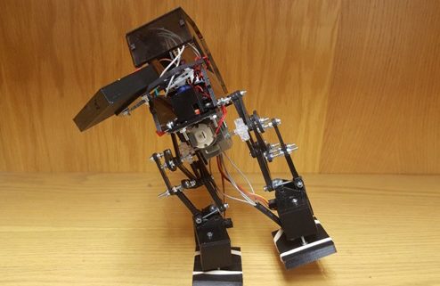
Team Biped will produce a two legged 6th generation toy biped robot that will replace the traditionally used servos with a dc motor and achieve static walking. By utilizing the 3Dot Board, the robot will participate in the end of semester, December 14th, 2016, game called: Save the Human.
Biped shall compete, alongside other toys such as Goliath and Velociraptors, in an end of semester approximately hour long game: Save The Human. Biped should successfully walk, using Goliath’s live video feed as the field of view, from the opposite end of the room to the finish area without coming into contact with a Velociraptor. The Biped will maneuver through multiple obstacles by turning through walls, sensing color pads, and stepping through uneven terrain placed on top of Linoleum floors.

A key component of our design is replacing the ankles with servos. The ankle servo eliminates having to use two dc motors to accomplish a pivot turn. The placement of the servos provides a strategic way to balance on on foot and then turn the entire body to face the desired direction.


| Vendor | Item | Unit Price | Quantity EE Dept. /Total | EE Dept. Extended Cost | |
| 1 | LOWE’S | Miscellaneous Hardware | 54.31 | 54.31 | |
| 2 | Mouser | Electronics | 27.82 | 27.82 | |
| 3 | Pololu | Hardware (Motor/Gearbox/ Wires) | 9.55 | 9.55 | |
| 4 | Hobby People | Electronics (Battery/ Connectors) | 16.33 | 16.33 | |
| 5 | Oshpark | Color Pad PCB | 0.60 | 0.60 | |
| 6 | Oshpark | Shield PCB | 20.45 | 20.45 | |
| Total: | 129.05 | ||||
| Allocated Budget | 125.00 |
[1] Project video
[2] PDR
[3] CDR
[4] Eagle Design
[5] Biped Code
[6] Solidworks
[8] PCB layout

By: Alan Valles (Electronics and Control)
Approved by: Ijya Karki (Project Manager)
Table of Contents
The purpose of this document is to provide suggestions for the next iteration of the design of the PCB shield for the Biped. These improvements are based on feedback and experience in the manufacturing, design and build of the PCB.
The engineering method is an iterative process. There are several suggestions and improvements that can be made to Biped schematics in [2] to improve performance of the system.
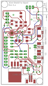
The Schematics since CDR were not revised much. However, after the realized PCB system was put together and tested, there are several updates that I would make for the next revision of the shield. I would add pin headers for the I2C bus. This would allow for flexibility in future iterations for the Biped Project. In the future, I also would have changed the design to incorporate locking headers like the Ph-series of battery and motor connectors for the rest of the external peripherals. These will allow for more secure connections. The combination of jumper wires and pin headers was not a fixed connection and caused major amounts of headache due to contacts not connecting. It lead to perplexing troubleshooting in order to see if bugs were software related or hardware related.
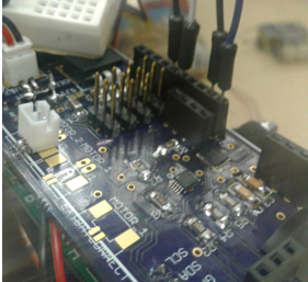
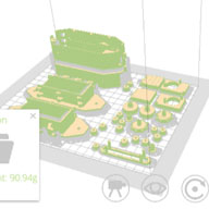
Figure 1. Circuit System.
Next, I would add a protection circuit to prevent reverse current in the event of reverse polarity. The chosen lm1084 does not have this built into it. However, the battery was hooked up with reverse polarity the first time. The LM1084 was a robust chip because after reversing polarity of input the LDO still held up fine and output 5V to the rest of the systems. TI offers some quick suggestions to mitigate this issue, by using a protection diode or FET as shown.
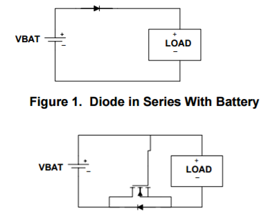
Figure 2. NMOS FET in the Ground Return Path.
Next, The Ext- connection was not solidly grounded on the PCB, rather it created a GND connection on the 3Dot board itself. To correct this issue, traces and or vias to GND plane can be created near the connector of the Battery for stronger connection to GND. Finally, another issue was that 3.3V and Ext+ were being paralleled on the PCB that was ordered. After discussion and analysis, the president and I were able to fix this by isolating the connecting point by cutting a copper trace. The GND connection on the shield was never connected to EXT- connection on the 3dot. A small wire was post manufacturing. But the future shield should tie these point together at some point. Also the SDA and SCL lines were crossed for A2D converter so that would obviously be fixed in next iterations.
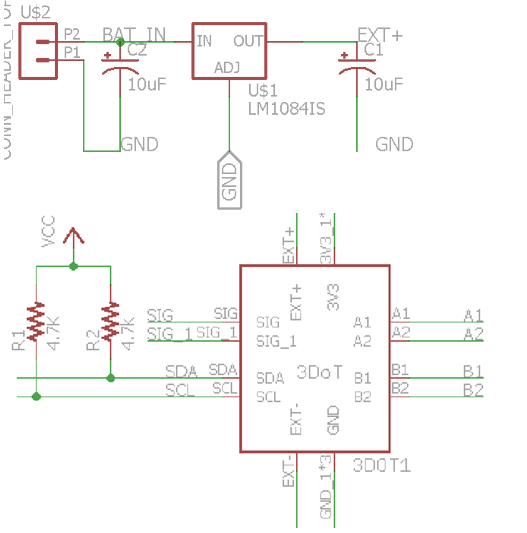
Figure 3. After PCB in Production.
These are some of the changes that were recognized after our PCB was in production that should be fixed for the next iteration.
In conclusion, the pin headers for encoder connector, and other external peripherals would be changed to a locking style, a reverse current protection circuit would be added and various clean up work would be done such as tying GND to Ext-.
[1] http://www.ti.com/lit/an/slva139/slva139.pdf
[2] http://arxterra.com/fall-2016-biped-updated-schematics/

By: Alan Valles (Electronics and Control) Approved by: Ijya Karki (Project Manager) Table of Contents Introduction The purpose of this blog post is to explain the function and design of the custom PCB color sensor that was made. Analysis This color sensor was made to meet our requirements and detect color pads below. Two version […]
By Inna Echual (Project Manager)
Table of Contents
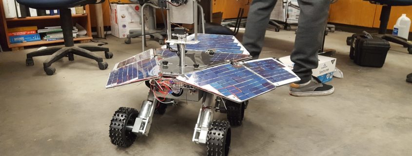
The design of the Fall 2016 Pathfinder project was taken directly from NASA’s Mars Exploration Rovers, Opportunity and Spirit. The Pathfinder will be designed to be self-sufficient using solar panels, as well as implement the solar deployment mechanism employed by the two aforementioned rovers. The solar panels should able recharge the Pathfinder’s battery allowing it to traverse rough terrain. The solar panels must also articulate to track the sun, maximizing the amount of solar power received.
The project will be demonstrated by parking the Pathfinder in the Central Quad on California State University, Long Beach located at 33°46’40.7″N 118°06’48.9″W. In addition to the location near the defined travel course, the parking spot was chosen as it had low traffic and free of shading. The parking spot is indicated in Figure 1.

Figure 1: Pathfinder Charging Spot

Figure 2: Pathfinder Charging Spot (Magnified)
This will be done using 5 strings in parallel of 30 solar cells stringed together in series to fit the customized solar shape of the aforementioned rovers (see compare our layout in Figure 3 with Spirit’s layout in Figure 4).
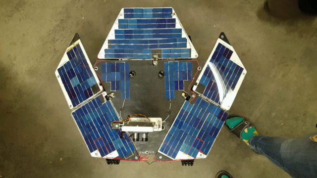
Figure 3: Fall 2016 Solar Panels
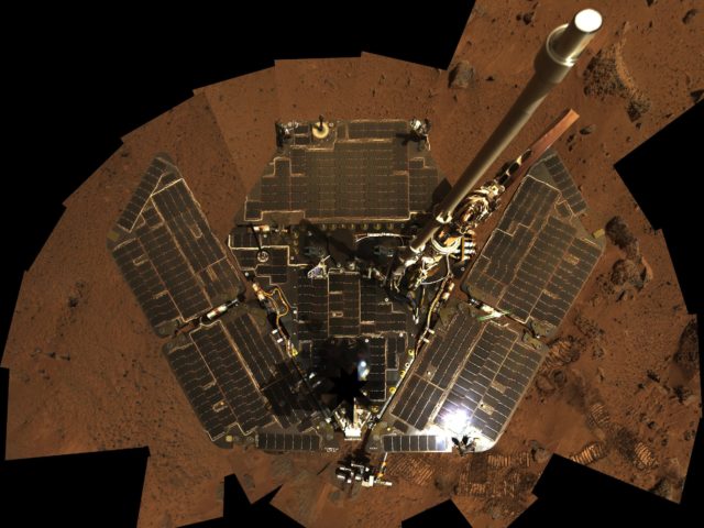
Figure 4: Spirit Rover Panels
The solar panels will be configured to be identical to the form factor of the solar panels on the Opportunity and Spirit rovers (see Figure 5).

Figure 5: Form Factor Consideration

Figure 6: Updated System Block Diagram from CDR
Updated System Block Diagram from CDR brief.
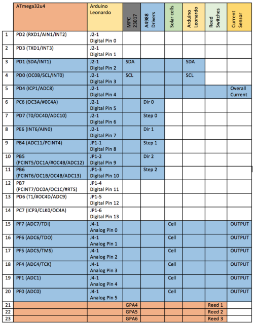
Figure 7: Interface Matrix
As defined in the mission profile, the Pathfinder will be allowed to travel a course on the upper campus of CSULB. This system is designed to replicate the Spirit & Opportunity Mars Rovers. The program objective is to be self-sufficient. In order for this system to be successful with it’s mission, the two systems; Chassis & Solar Panel, must work together with one another. The Solar Panel will be in charge of supplying power to the battery, and the Chassis will then be able to use this battery and travel the course.
The Interface Control Document will be used to provide an outline for the responsibilities aligned with each system. It also sets out the interfacing requirements to help move the design forward for each of our systems in the following disciplines: Mechanical Interfacing, Power Transactions, and Control Mechanism & Data Transfer. It also includes some constraints, assumptions, and possible risks involved in these factors.
Interface Control Document
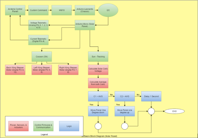
Figure 7: Software Block Diagram
The software block diagram in Figure 7 explains an overall understanding of what the Solar Panel system’s software entails. It also includes a portion of the Chassis system and how we are interfacing with one another electronically, along with a legend on the bottom left to help detect what the different colors mean.
DC Motor With Encoder Experiment
Creating a Port Expander Using IC MCP23017
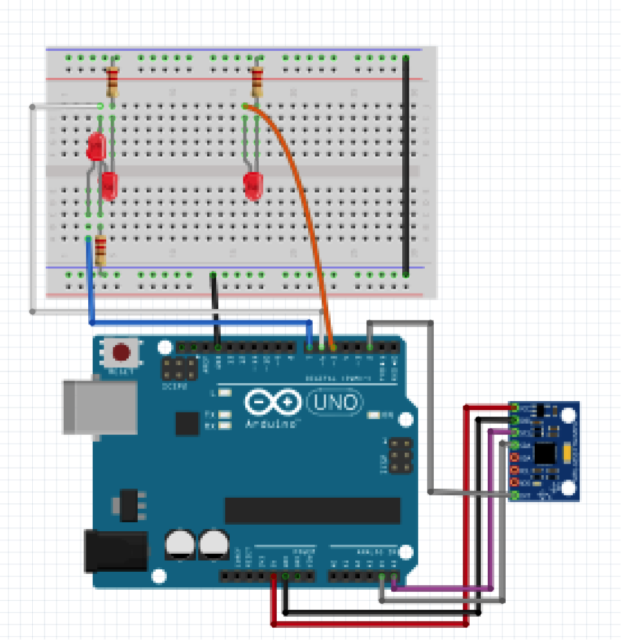
Figure 8: Fritzing Diagram for Motor Driver
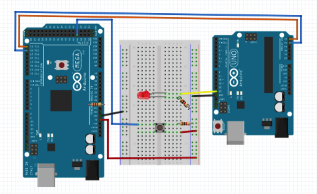
Figure 9: Fritzing Diagram for I2C Communication
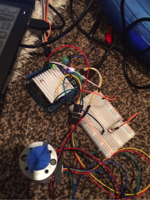
Figure 10: Breadboard for Motor Driver
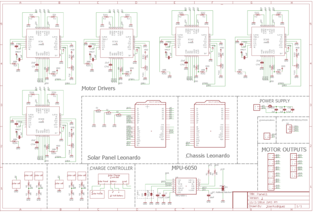
Figure 11: Schematic
Folding Mechanism Trade-Off Study
Choosing Panel Thickness / Stress Tests

[1] Project Video
[2] Critical Design Review (CDR)
[3] Preliminary Design Review (PDR)
[4] Project Schedule
[5] Verification and Validation Documents
[10] Bill of Materials
[11] Final Interface Control Document (dated 12/13/16)
[1] Spirit Rover Cleaned: https://commons.wikimedia.org/wiki/File:Spirit_Rover_Cleaned.jpg

By: Brandon Perez (Missions, Systems, and Test)
Approved by: Ijya Karki (Project Manager)
| Req. No. | “The Biped Shall” Statement | Success Criteria | Method | Results | Pass / Fail |
This report covers the Test Plans for Verifying and Validating our Requirements.
| L1-1 | Shall be ready to participate in the game “Save The Human” on December 14th, 2016. | The project must be fully functional and presentable by December 14th, 2016. | Demo | FAIL | |
| L1-2 | Shall not exceed a cost of $125.00 to construct. | The project must not exceed a budget of $125.00. | Inspect | PASS | |
| L1-3 | Will use a 3Dot board, have a custom PCB, and utilize the I2C interface. | The project must contain a 3Dot board as the main control unit for the system, have a custom-built PCB, and utilize the I2C interface on the 3Dot board. | Inspect | PASS | |
| L1-4 | Shall be able to walk a minimum speed of 0.32mm/sec. | The Biped shall have to walk a straight path at a speed of 0.32mm per second. | Test | FAIL | |
| L1-5 | Shall be able to turn up to 180 degrees on each of its sides. | When the Biped is initiating a turn, the angle that it turns its body shall be any angle ranging from 0-180 degrees. | Test | PASS | |
| L1-6 | Shall be controlled telepathically up to 20ft away through the Arxterra App. | When controlling the Biped via Arxterra Control Panel on a mobile device, the Biped shall be able to be controlled up to 20ft away from the user. | Test | PASS | |
| L1-7 | Will have a mass less than or equal to 750 grams. | The total Biped’s mass shall not exceed 750 grams. | Test | PASS | |
| L1-8 | Shall be able to operate for a minimum duration of 1.00 hour. | The Biped system shall have to operate for a minimum duration of 1.00 hour | Test | PASS | |
| L1-9 | Should be able to walk on angled surfaces with max slope of (+/-) 6.5 degrees. | The Biped should be able to walk on inclines of 6.5-degree slope and declines of -6.5-degree slope. | Test | FAIL | |
| L1-10 | Should be able to walk on uneven surface heights of 0.5 cm or less. | The Biped shall remain stable when walking over obstacles spread over the ground which shall have heights ranging from 0 mm to 5 mm. | Test | FAIL | |
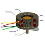
| L2-1 | Will have a DC motor that can operate effectively at 5V and produce torque of 9.75e-3 ft*lbs. | The DC Motor shall have an operating voltage of 5V or greater and shall have to produce a minimum torque of 9.75×10^-3 ft*lbs. | Test | PASS | |
| L2-2 | Will have servos that can operate effectively at 5V and horizontally move a mass of 68g. | The servos being used to control the Bipeds arms shall have an operating voltage of 5V or greater and shall be able to turn horizontally the Biped’s arm’s mass of 80g. | Test | PASS | |
| L2-3 | Will have a rotary encoder to read the shaft’s position at a rate of 40 times the Motor RPM. | The shaft encoder shall give a reading of the shafts position at a minimum rate of 40x[Motor RPM] to ensure the MPU has a resolution | Test | PASS | |
| L2-4 | Shall use an RGB LED to display the color of the color pad for a minute duration. | When the Biped steps on top of the color pads, the color of the pads shall be displayed on the RGB LED for a minute duration. | Test | PASS | |
| L2-5 | Should have an IMU to detect inclines and decline angle deviations up to (+/-)6.5 degrees. | The IMU should provide readings of the angle deviation when the Biped is walking on angled surfaces for all angles between -6.5 and 6.5 degrees. | Test | FAIL | |
| L2-6 | Will use a battery with a capacity rated at 560mAh or greater. | The battery for the system must be rated at a capacity of 560mAh or greater. | Inspect | PASS |
Level 1 Requirement 1:
Shall be ready to participate in the game “Save The Human” on December 14th, 2016.
Tools:
Procedure:
RESULTS: By the time of final demonstration, the Biped was not able to walk. Our DC Motor Gearbox had gears that would constantly slip against each other causing our walk movement to stall at most times. In result, we did not meet the schedule requirement.

Level 1 Requirement 2:
Shall not exceed a cost of $125.00 to construct.
Tools:
Procedure:
RESULTS:

We have totaled $129.05 of expenses so we are $4.05 over budget. Regardless that we are over budget, we have still been within the customer’s contingency which is a reasonable 3.2% over budget.

Level 1 Requirement 3:
Will use a 3Dot board, have a custom PCB, and utilize the I2C interface.
Tools:
Procedure:
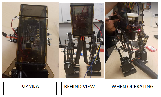
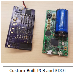
RESULTS: In the 3 pictures, below, we show 3 different perspectives of the of the 3DOT board and PCB encasement in our Biped.
The 3Dot’s board 12C peripheral interface pins are mapped to the custom built PCB for I/O access. Since we have a 3Dot board, a custom-built PCB, and are utilizing the I2C interface, this requirement has been met.
In the 3 pictures, below, we show 3 different perspectives of the of the 3DOT board and PCB encasement in our Biped. The 3Dot’s board 12C peripheral interface pins are mapped to the custom built PCB for I/O access. Since we have a 3Dot board, a custom-built PCB, and are utilizing the I2C interface, this requirement has been met.
Level 1 Requirement 4:
Shall be able to walk a speed of 0.32mm /sec.
Tools:
Procedure:
RESULTS: Unfortunately, our Biped was unable to walk without falling over. To point out the obvious issues, too much mass had been concentrated in the front of the Biped which caused it to fall frontward. For improvement up our design, we should extend the feet out by about 1cm.
Level 1 Requirement 5:
Shall be able to turn 180 degrees on each of its sides.
Tools:
Procedure:
RESULTS:
We began this test by initiating a turn on the Biped when it was standing on one leg.
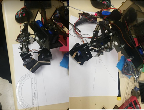
The Biped was able to take a turn here of 44 degrees when standing on one leg. The turning requirement was set to be accomplished when walking, however we were able to independently turn without ever be in the walking motion, therefore this requirement has been met to some degree of turning, literally.
Level 1 Requirement 6:
Shall be controlled in RC mode in the Arxterra App up to 20ft away.
Tools:
Procedure
RESULTS:
We began this test by setting up the Biped 20ft away from the user who was sending commands via Arxterra control.
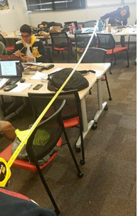
Due to limited time, we had only tested directly above 20ft away. In the picture you can see the view of a tape measure being extended out to confirm we were at least 20 ft away from the Biped to meet the RC Mode requirement. We could confirm that our biped was still able to receive commands at 20ft away, therefore we met this requirement.
Level 1 Requirement 7:
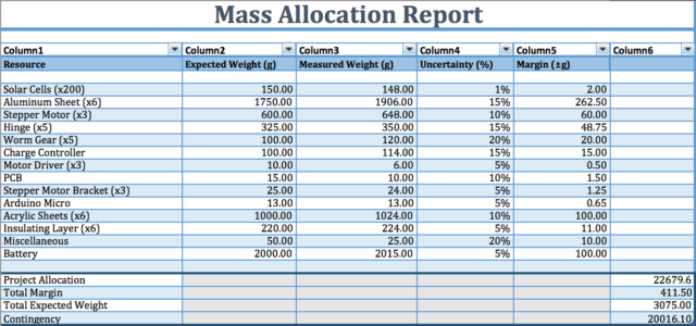
Will have a mass less than or equal to 750 grams.
Tools:
Procedure:
RESULTS:
We begin by setting our Biped on the scale to determine its final mass.
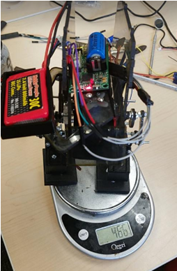
The mass of the Biped is measured to be 466 grams. The mass requirement for our Biped is to be less than or equal to 750 grams, therefore this requirement has been met.

Level 1 Requirement 8:
Shall be able to operate for a minimum duration of 1 hour.
Tools:
Procedure:
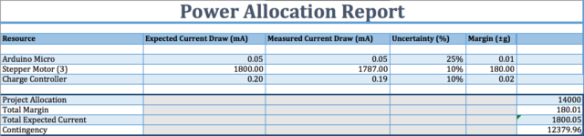
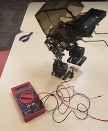
RESULTS: We begin the test by measuring the current drawn from the battery when the Biped is running the motor to produce its walking motion. We use an ammeter in series with the battery terminal and the DC motor pin. We recorded a video for a minute duration and then extracted the values from the ammeter throughout the video and provided them below.
We begin the test by measuring the current drawn from the battery when the Biped is running the motor to produce its walking motion. We use an ammeter in series with the battery terminal and the DC motor pin. We recorded a video for a minute duration and then extracted the values from the ammeter throughout the video and provided them below.
Data Collected from Ammeter: [0.68 0.14 0.12 0.14 0.10 0.19 0.09 0.37 0.33 0.93 0.47 0.48 0.38 0.35 0.44 0.41 0.45 0.40 0.47 0.33 0.42 0.61 0.57 0.42 0.37 0.88 0.39 0.53 0.64 0.87 1.14 0.98 0.64 0.82 0.46 0.48 0.29 0.33 0.58 0.41 0.55 0.39 0.50 0.56 0.72 0.90 0.40 0.60 0.49 0.71 0.40 0.66 1.21 0.75 0.34 0.39 0.52 0.35 0.36 0.98 0.42 0.54 0.54 0.51 0.71 0.72 0.76 0.96 0.78 0.51 0.59 0.34 0.31 0.26 0.62 0.33 0.20 0.28 0.25 0.20 0.42 0.51 0.62 0.61 0.43 0.57 0.66 0.45 0.36 0.52 0.42 0.38 0.45 0.32 0.18 0.22 0.28 0.32 0.20 0.41 0.37 0.48 0.52 0.58 0.27 0.29 0.35 0.27 0.14 0.22 0.19 0.16 0.13 0.20 0.21 0.29 0.40 0.55 0.46 0.55 0.48 0.46 0.40 0.34 0.23 0.25 0.35 0.37 0.25 0.30 0.24 0.35 0.31 0.29 0.49 0.54 0.48 0.56 0.62 0.38 0.24 0.19 0.15 0.25 0.28]
I then proceeded to calculate the average in MATLAB.
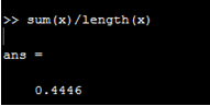
Since our walking motion is our most energy expensive operation, we can assume that we walk the entire duration of the game to get the maximum energy expense throughout the entire game duration.
If we assume the Biped will be walking the entire game, (which in reality, it won’t) it would consume 440mA x 1hr = 440 mAh of energy from the battery. Since our battery can provide 800 mAh of energy theoretically, then our battery should have sufficient energy for providing power to the Biped for the entire game duration of an hour.
Level 1 Requirement 9:
Should be able to walk on angled surfaces with max slope of (+/-) 6.5 degrees.
Tools:
Procedure:
RESULTS: Unfortunately, our testing and design had been narrowed and focused towards the walking portion of the design, so we disregarded testing on inclines.
Level 1 Requirement 10:
Should be able to walk on uneven surface heights of 0.5 cm or less.
Tools:
Procedure:
RESULTS: Unfortunately, our testing and design had been narrowed and focused towards the walking portion of the design, so we disregarded testing walking on uneven surfaces.
Level 2 Requirement 1:
Will have a DC motor that can operate effectively at 5V and produce torque of 9.75e-3 ft*lbs.
Tools:
Procedure:
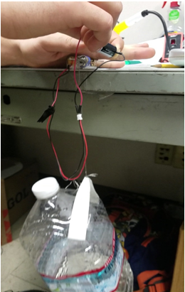
RESULTS: We have set our DC motor torque requirement in the units of ft*lbs for making our calculation easier. We proceed to measure the diameter of our motor shaft to determine its radius.
We used calipers to measure the DC Motor shaft diameter.

T = F*L
T = 9.75×10^-3 ft*lbs
L = 2.6mm/2 = 1.3mm
1.3mm = 0.0043 in
F = (9.75×10^-3 ft*lbs)/(4.3×10^-3 ft) = 2.26 lbs = 36.28 oz
Since our DC Motor is already rated at 5V, no test must be done for the first part of the requirement. As far as the torque requirement, the DC Motor was successfully able to lift the gallon of water up, therefore this requirement has been met.
Level 2 Requirement 2:
Will have servo that can operate effectively at 5V and horizontally move a mass of 68g.
Tools:
Procedure:
RESULTS:
Since our servo is rated at 5V already, no test is necessary for the first part of the requirement. To check if our servo can horizontally move a mass of 68g, we set the servo upright and attach a platform to carry the several different masses.

It was found through this experiment that the servo could horizontally move the masses on top of the platform up to 400g. We concluded that we that servo could meet the requirement so we suspended further testing of heavier masses.

Level 2 Requirement 3:
Will have a rotary encoder to read the shaft’s position at a rate of 40 times the Motor RPM.
Tools:
Procedure:
RESULTS:
We began this test by timing how long it too our motor to turn its shaft a full 360 degrees under the load of the legs it must move.
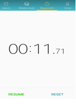
Time per motor revolution: 11.71sec
MOTOR RPM = (60secs per min)/(11.71sec) = 5.12
Therefore, our rotary encoder must read values at a rate of 40×5.12 = 204.8 times/minute to get a sufficient resolution of the shaft position.
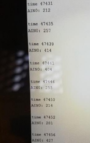
We then began to try and measure how fast our rotary encoder could take values so wrote an Arduino code to write a timestamp after every rotary encoder reading.
Our values being outputted at the computer for time are in units of milliseconds. If you look at the picture at the left, you can see that each of the time readings are spaced by 4 milliseconds.
Therefore the sample rate for our rotary encoders ADC is 60/(4×10^-3 Hz) = 15,000 times per minute.
This sample rate is clearly sufficient for our system, therefore this requirement is met.
Level 2 Requirement 4:
Shall use an RGB LED to display the color of the color pad for a minute duration.
Tools:
Procedure:
RESULTS:
We began testing the color sensor by seeing if our sensor was reading values. We placed the Biped above 3 different colored construction papers of color red, blue, and green.
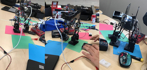
The above pictures show our Biped testing the color sensor on the foot. To determine if our color sensor was reading the values, we send the sensor values via seirial communciation to be displayed on our computer.
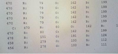
We were able to successfully distinguish the color of the construction with the data we were receiving on our monitor. Our color sesnor was sucessful, however we were not able to display the value on the RGB LED since our GPIO expander on our custom PCB was having issues.
Level 2 Requirement 5:
Should have an IMU to detect inclines and decline angle deviations up to (+/-)6.5 degrees.
Tools:
Procedure:
RESULTS: Due to limited time, we decided to not include an IMU in our final design since it would require more testing and its effectives would only benefit us if our system had already passed walking.
Level 2 Requirement 6:
Will use a battery with a capacity rated at 560mAh or greater.
Tools:
Procedure:
RESULTS:
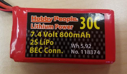
Our battery is rated at 800 mAh, therefore this requirement has been met.
