
By:
Peiyuan Xu (Project Manager)
Approved by Peiyuan Xu (Project Manager)
Approved by Xiong Lee (System Engineer)
Table of Contents
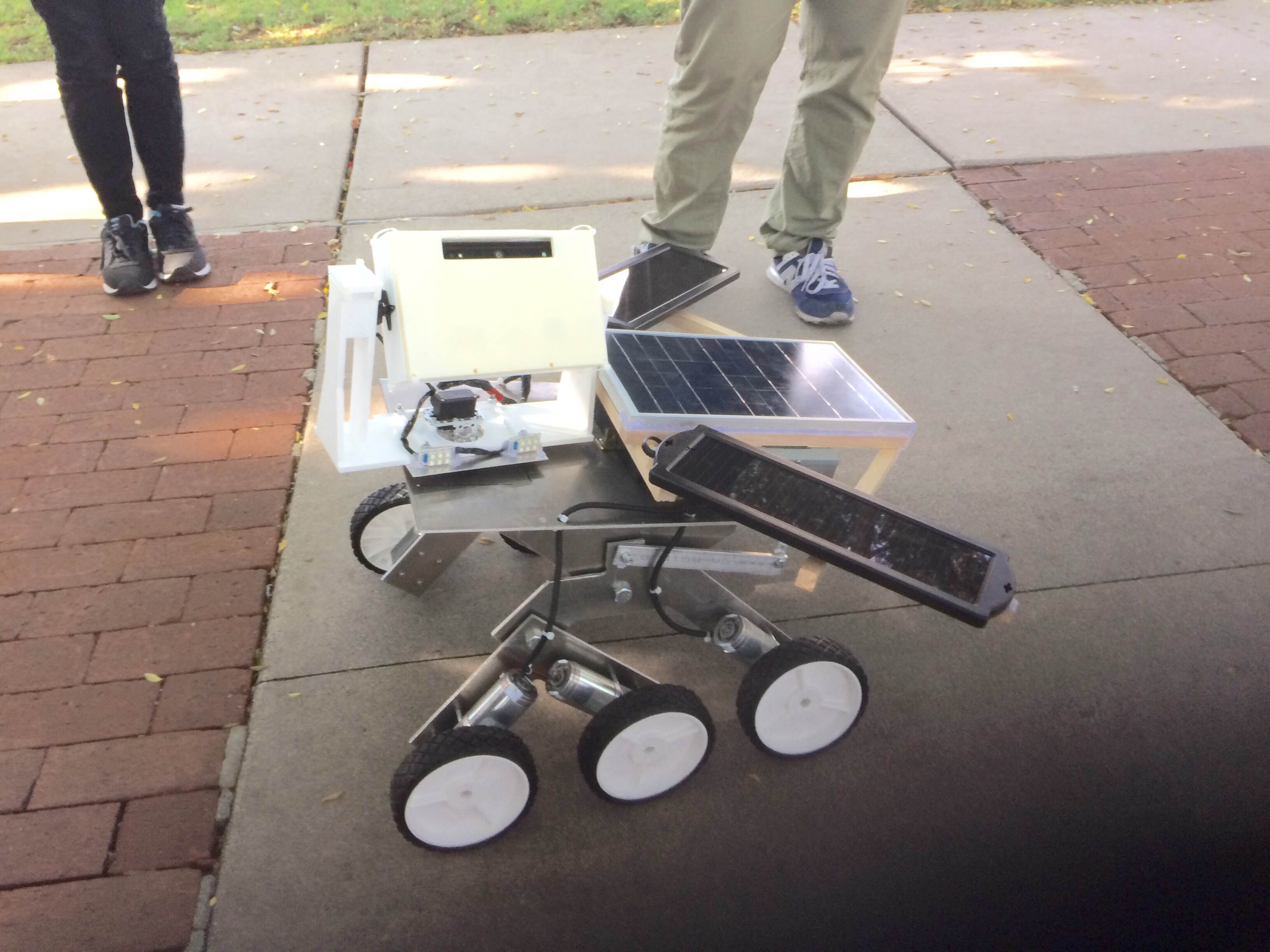
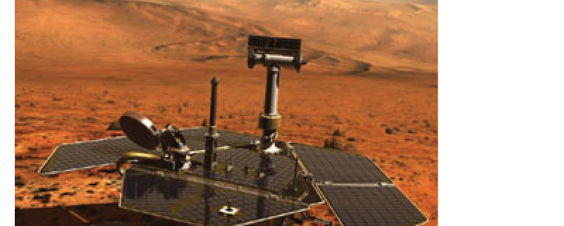
The spring 2016 Pathfinder Rover was inspired by NASA’s MARs Exploration Rover-“Sojourner”. The profile for this semester’s project is to imitate the design of “Sojourner” Rover to prototype a new generation of Pathfinder Rover that implements the Rocker Bogie Suspension System as well as being self-sufficient by using solar panels. The Pathfinder is allowed to have the solar panels charging the battery for up to 8 hours during the day time. Then the customer can spend up to 4 hours at night walking and exploring with the Pathfinder. Ultimately, The customer can use Arxterra control panel on the PC to navigate the Rover by using the cursor to click a point on the map. This generation of Pathfinder Rover is also designed to test and implement SLAM (Simultaneous Localization and Mapping) technology for autonomous vehicles.
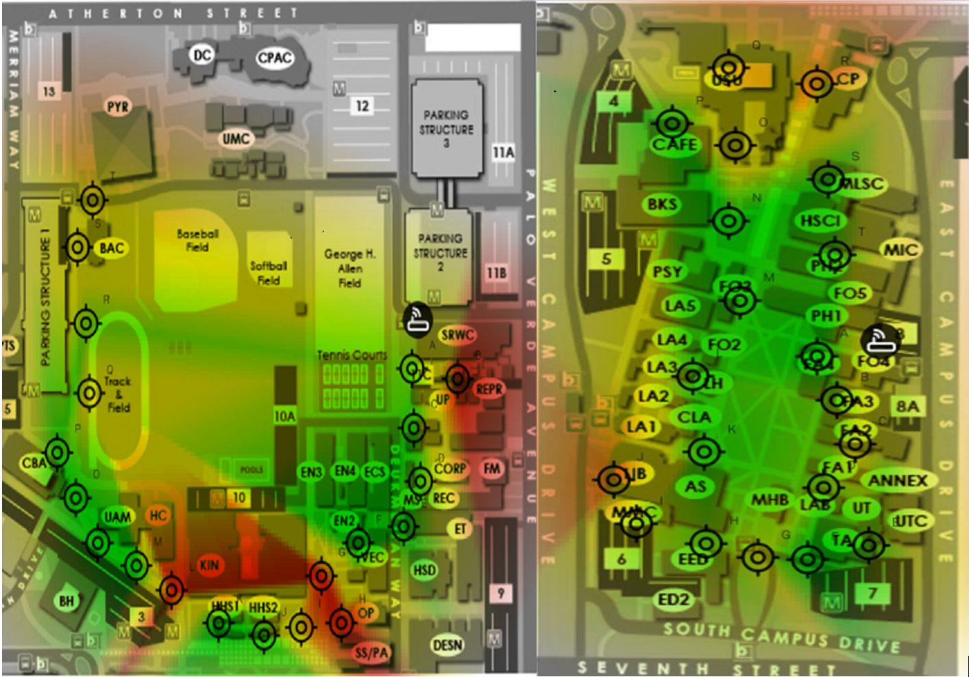
![]() Figure 1 – CSULB WiFi Strength map
Figure 1 – CSULB WiFi Strength map
Since our Pathfinder Rover will be tested at the entire CSULB campus. We need to find out where there is the best Wi-Fi signal in order to gain the stable video stream from the android phone to the Arxterra. The system engineer Xiong Lee was able to use an android App called Wi-Fi Maximiser to map out the Wi-Fi signal strength around CSULB campus. Based on the strength of the Wi-Fi signal, our mission will be narrowed down to the area covered with green on the map. We suggest the customer not to go through the area covered with red because there might be some packet loss and signal lag around the area. We also think this Wi-Fi signal strength map can be useful for other EE 400D project in which case they need to explore the CSULB campus as well.
The changes that made to the Mission Profile and Project Objective can be found here:
Spring 2016 Pathfinder: Mission Profile and Project Objective Update
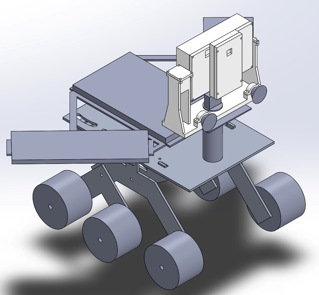
Figure 2 – 3D Model
The image above is the 3D illustration in SolidWorks that shows the overall design of the pathfinder.
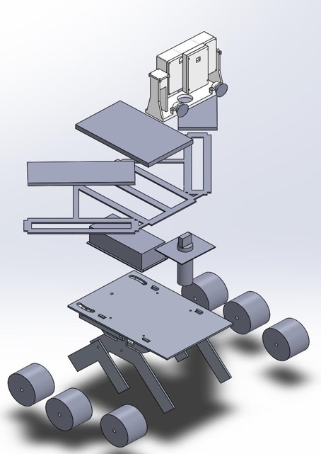
Figure 3 – Exploded Model
This image above gives the exploded view of the Project design. On the top is the Tilt system with the encasement for Google Tango tablet and Android Phone. Below that are the 3 solar panels with resemble the shape of the Arxterra logo. Then there is a metal box to protect all the electronic components. Following that is our new chassis with Rocker Bogie System.
For more details on the structures of this design, refer to:
Spring 2016 Pathfinder Design and Manufacturing – Rocker Bogie Suspension System Design
Spring 2016 Pathfinder Design and Manufacturing – Tilt System Finalized Design
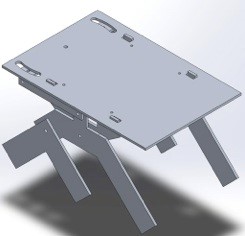
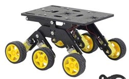 Figure 4 – Rocker Bogie System

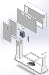 Figure 5 – Tilt System
 Figure 6 – Solar Panels
Access to the Point Cloud Data (send data out via Tango Bluetooth API)
Use Depth perception and IMU sensors to navigate Pathfinder go where the user wants to go (Developing)
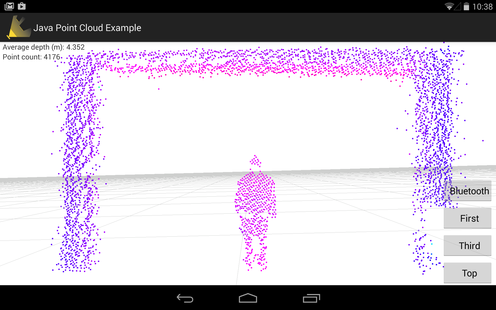 Figure 7 – Point Cloud App
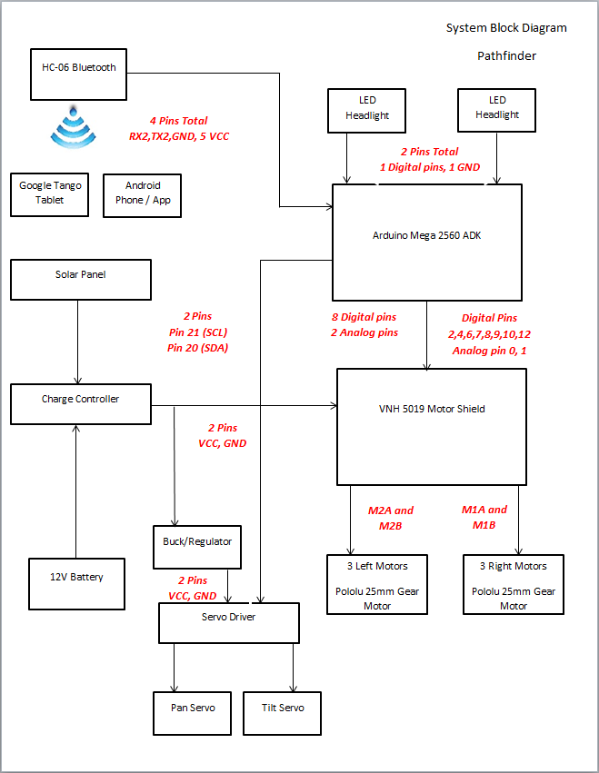 Figure 8 – System Block Diagram
The system block diagram above shows how all of the components interface with each other. First, transmission of data from an android phone or the Arxterra control panel via HC-06 Bluetooth module will tell the Arduino Mega what to do. The Arduino Mega will interpret this data and send it out through the motor shield or servo driver to drive the pathfinders movement. The system block diagram also depicts how the charge controller will interface the power supply and the solar panels to the VHN5019 Motor shield that will drive the pathfinder.
For more information about the system design, refer to:
Spring 2016 Pathfinder: System Block Diagram & Interface Matrix
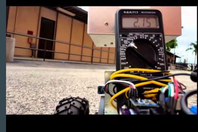 Figure 9 – Current Drawn Test
The purpose of this test is to find the current drawn by the motors on different terrains and in different driving modes (Braking abruptly, Rotating (Under High Stress) and Running forward/backward (Normal Driving) . This test is crucial for us to gain the discharging time of the batteries in order to meet the Level 1 requirement of constantly running for 4 hours.
For Project Level 1 requirements, refer to:
http://arxterra.com/spring-2016-pathfinder-preliminary-project-plan/
Peak current: 4.8 A (Under highest stress)
-Ex. braking abruptly, rotating, etc
Average current: 1.2 A (Normal driving)
Theoretical discharge time:
20 Ah / 4.8 A = 4.16 hours (high stress)
20 Ah/ 1.5 A = 13.33 hours (normal driving)
Actual Discharge time to 50% : 6.5 hours
This test is conducted for the Wild Thumper chassis
For more information about this current drawn test, refer to:
Spring 2016 Pathfinder: Current Drawn Test
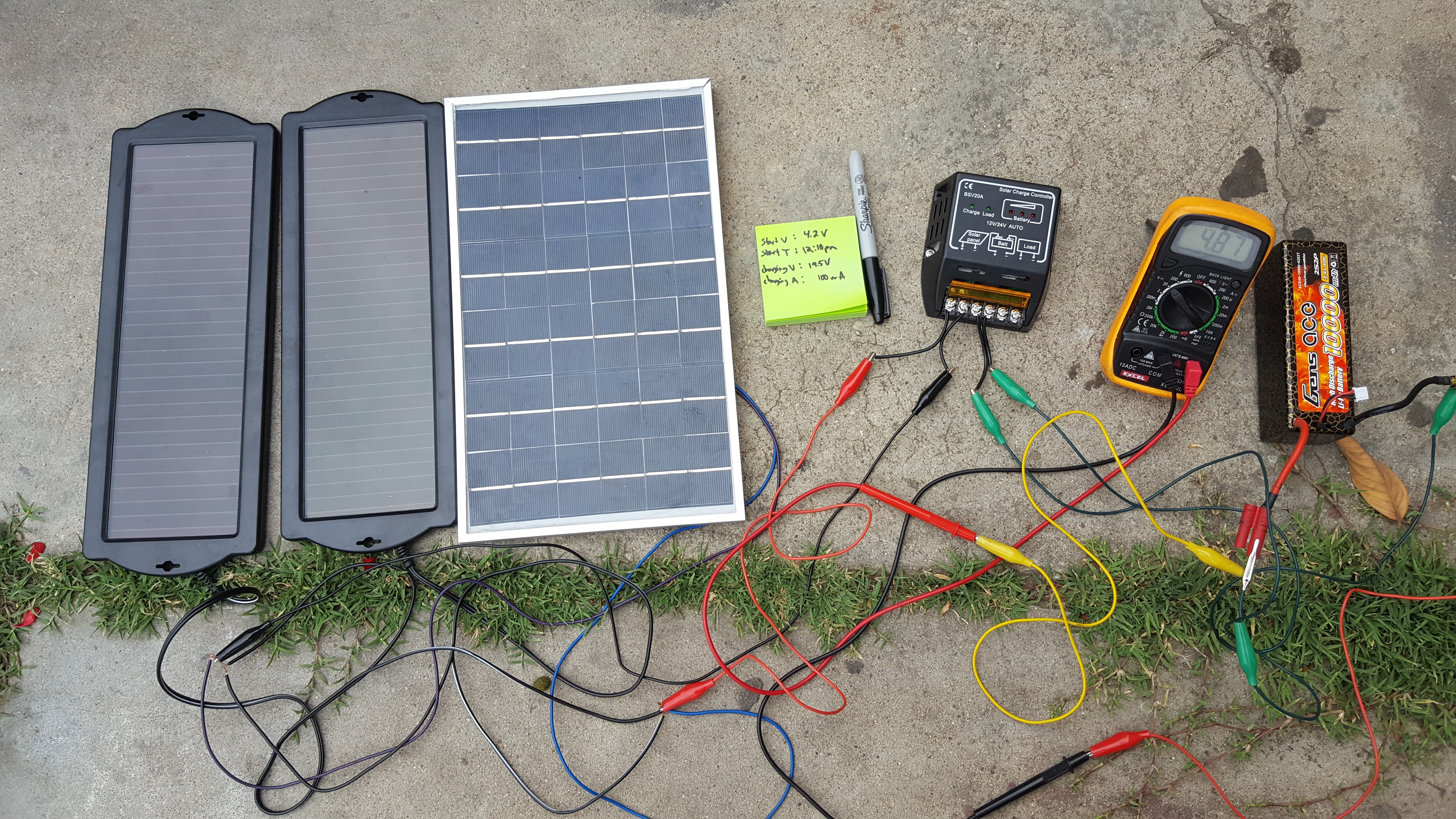 Figure 10 – Solar Panels charging the batteries
The project objective stated that the pathfinder needs to be self-sufficient by using solar panels. This test is to measure the total current the solar panels can supply at direct sunlight. In reality, the charging capability of solar panels will vary depends on the weather condition, therefore, we include some of the other tests for comparison of the worst case scenario.
-Direct sunlight: 850 – 950 mA
-Shady area: 500 – 750 mA
-Rain or cloudy: 100 – 300 mA
For more information on how we implement solar panels, refer to:
Spring 2016 Pathfinder Solar Panels Implementation
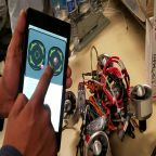
Figure 11 – Project Tango: Point Cloud
This spring 2016 Pathfinder project used Google’s Project Tango as a platform to test and implement SLAM (Simultaneous Localization and Mapping) technology for autonomous vehicles. Project Tango uses computer vision to give device the ability to know the position in the relative 3D space as well as the distance from the surrounding objects to the device itself.
For more research work of the Project Tango, refer to:
Spring 2016 Pathfinder: Project Tango Preliminary Research
For more details of the project Tango modules our team accomplished or attempted, refer to:
Spring 2016 Pathfinder: Project Tango Bluetooth API
Spring 2016 Pathfinder: Project Tango – Interactive Visualization of data from Tango using Paraview
Spring 2016 Pathfinder: Project Tango Module#5 – Android to Arduino Via Bluetooth
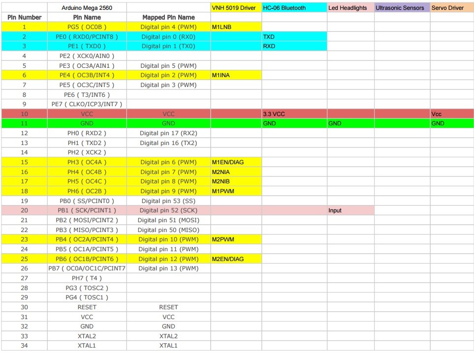
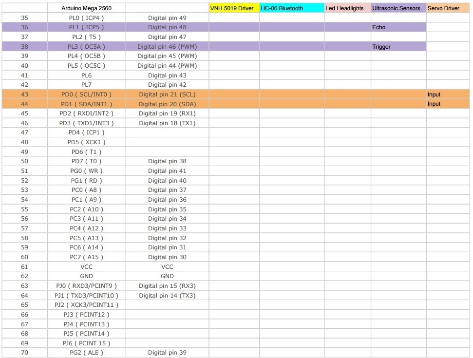
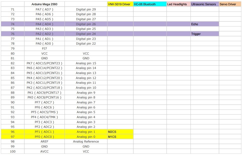 Figure 12 – Interface Matrix
The above interface matrix shows in depth on which pins are used on the Arduino Mega.
For further details on interface matrix, refer to:
Spring 2016 Pathfinder: System Block Diagram & Interface Matrix
One improvement we had after PDR debrief was to highlight the rows and columns with different colors in the interface matrix. Each color represents the corresponding pins used by the component. That makes it a lot easier for us to track the subsystem level pinouts. Also this makes it easy for audience to see during the presentation.
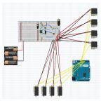
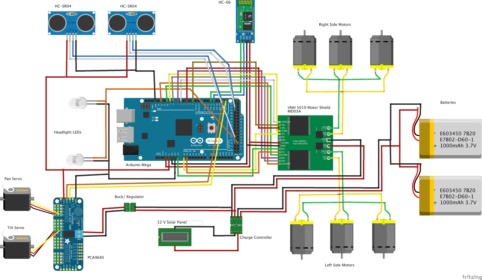 Figure 13 – Fritzing Diagram
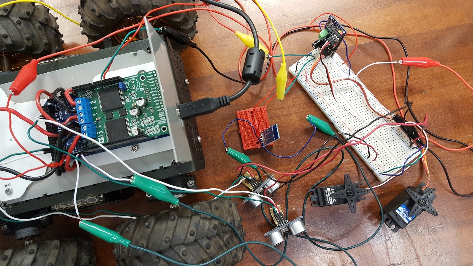 Figure 14 – Breadboard
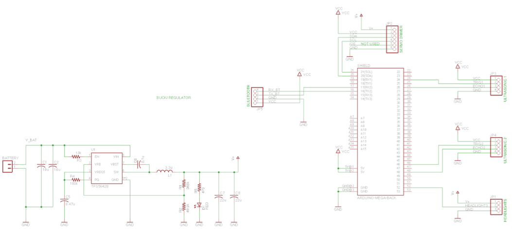 Figure 15 – PCB System Schematic
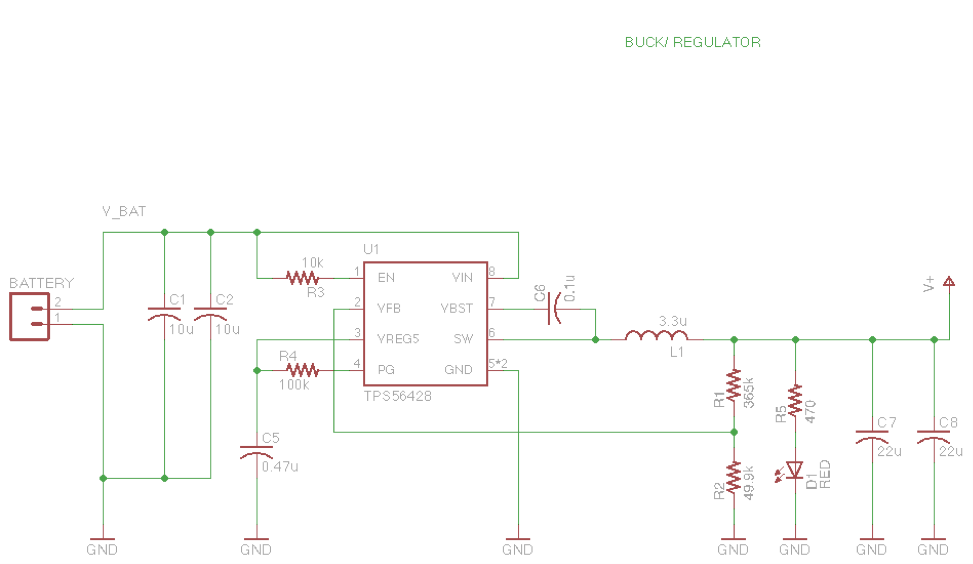 Figure 16 – Buck Regulator
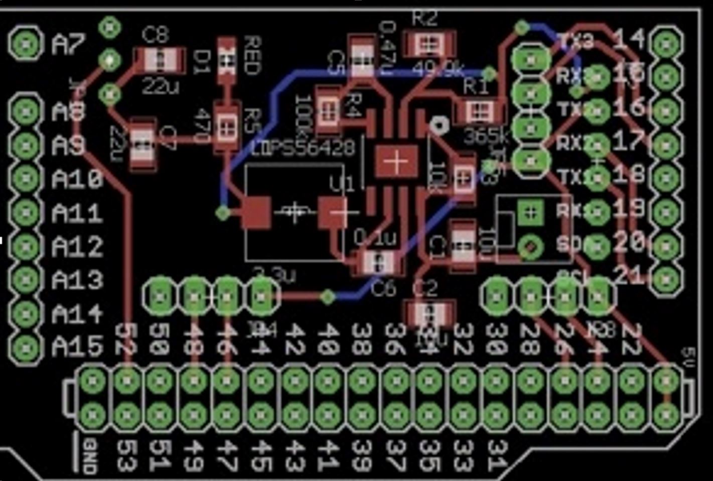 Figure 17 – PCB Layout
The pathfinder project needs a custom PCB to integrate all the electronic components, which included: VNH5019 motor shield, PCA9685 Servo PWM Controller, two servos, six DC motors, HC-06 Bluetooth Module, two HC-SR04 ultrasonic sensors, two LED Headlights. The custom PCB also take advantage of the leftover pins on the Arduino Mega. A buck regulator is required to step down the voltage from 12 V to 5.5 V in order to protect the servo driver. The advantage of using buck regulator over the voltage regulator is to keep a constant current.
For further details about the PCB system schematic design and layout, refer to:
Spring 2016 Pathfinder: PCB System Schematic
Spring 2016 Pathfinder: Design and Manufacturing – PCB Layout
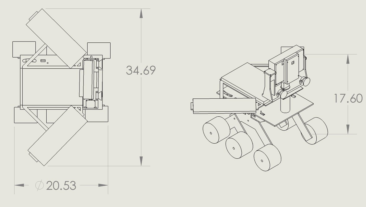 Figure 18 – Pathfinder overall Design
Figure 19 – 3D Illustration
Figure 20 – Exploded View
Figure 21 – Rocker Bogie System
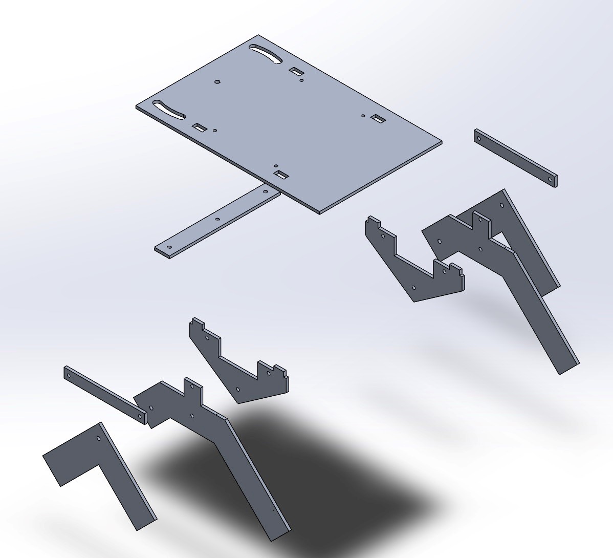 Figure 22 – Exploded View
Figure 23 – Tilt System
Figure 24 – Exploded View
These above pictures demonstrate the hardware design from the overall 3D models to breakdowns parts of the pathfinder rover design.
The goal of Spring 2016’s Pathfinder is to hold a Google Tango tablet, phone, solar panels in the shape of the Arxterra logo, a tilt system, and an electronic box. To best traverse obstacles, a rocker bogie suspension system design was chosen, with a top surface area of 12in x 18in. Modeled after ServoCity’s runt rover, the chassis was scaled to meet the surface area required for the above mentioned parts. The tilt system was designed to hold the tablet, phone and tilt servo. Lastly, all parts were modeled on the chassis.
For further details of the hardware design, refer to:
Spring 2016 Pathfinder Design and Manufacturing – Tilt System Design
Spring 2016 Pathfinder Design and Manufacturing – Tilt System Finalized Design
Spring 2016 Pathfinder Design and Manufacturing – Rocker Bogie Suspension System Design
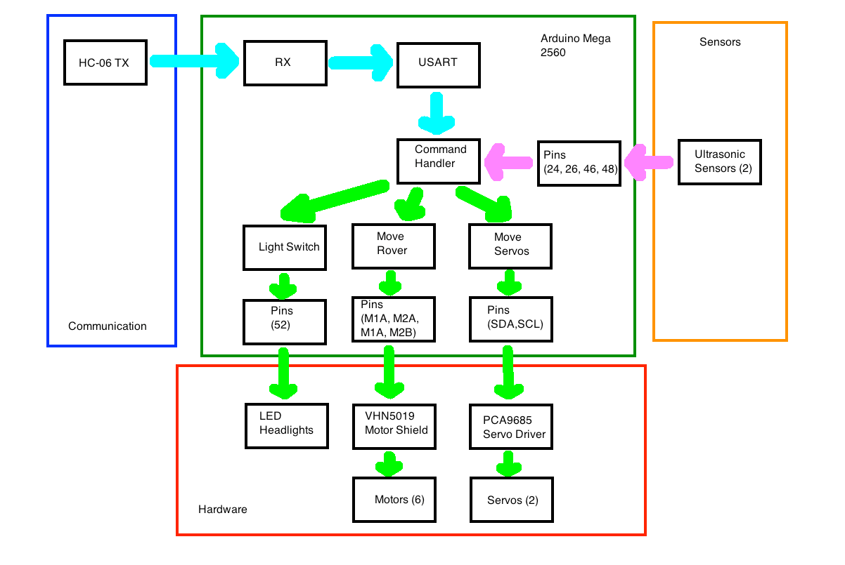 Figure 25 – Software System Block Diagram
The software design follows the system block diagram and focus on the subsystem level software modules development.
For further details on how each software modules works, refer to:
Spring 2016 Pathfinder: Software Design
For reference of Arduino code controlling motors and servos through coolterm, refer to:
Spring 2016 Pathfinder: Software Design
For reference of controlling motors through Arxterra, refer to
Spring 2016 Pathfinder: Bluetooth Communication with the Arxterra App
For reference of controlling servos through Arxterra, refer to
Spring 2016 Pathfinder: Arxterra Servo Control for Pan and Tilt
Verification and Test Plans are required to prove that the project can meet the L1/L2 requirements.
Since our team received new requirements of building a new pathfinder in a short period of time, many of the verification tests had not yet been done due to the heavy work of manufacturing. The project final demo then was been used for some of the verification and validation tests.
For more details of the verification matrix and Validation Test Plans, refer to the “project resource”
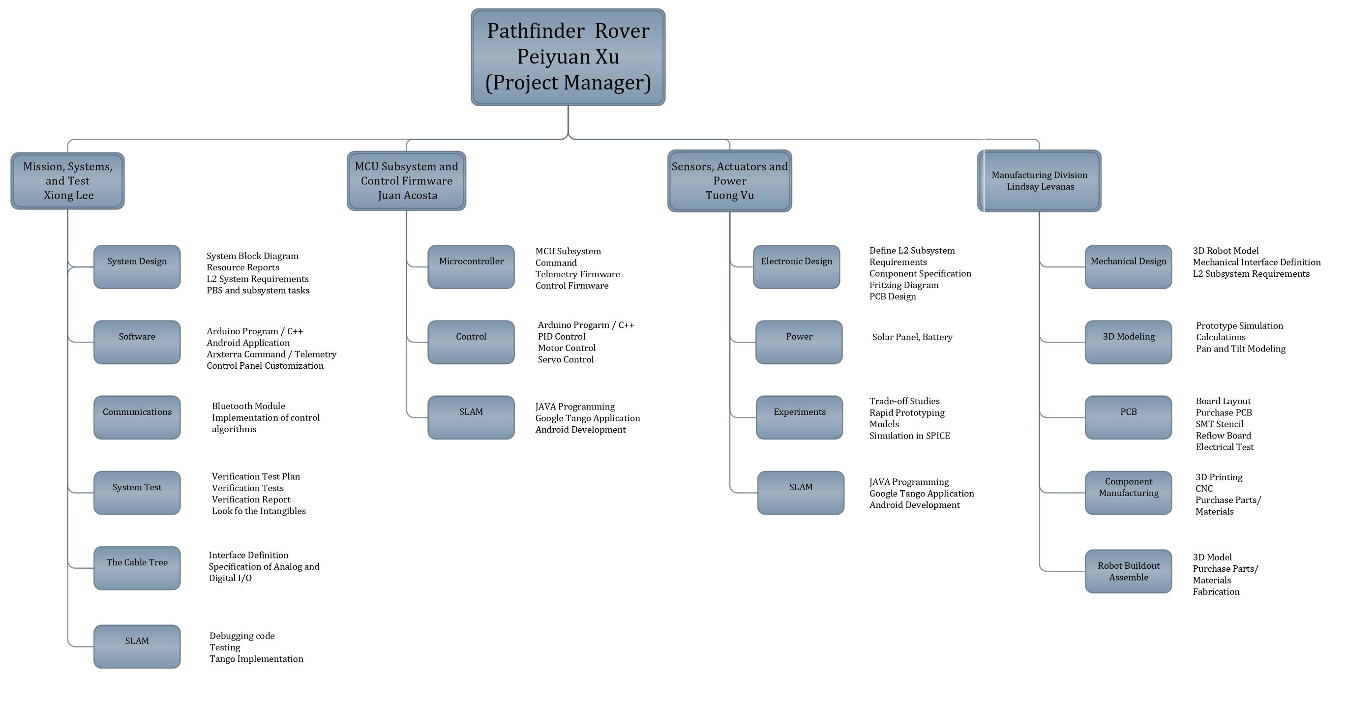 Figure 26 – Work Breakdown Structure
This work breakdown structure demonstrates all the work needed to be done for this project Pathfinder Rover. There are four branches that indicates different job duties and division works assigned to the system and subsystem engineers.
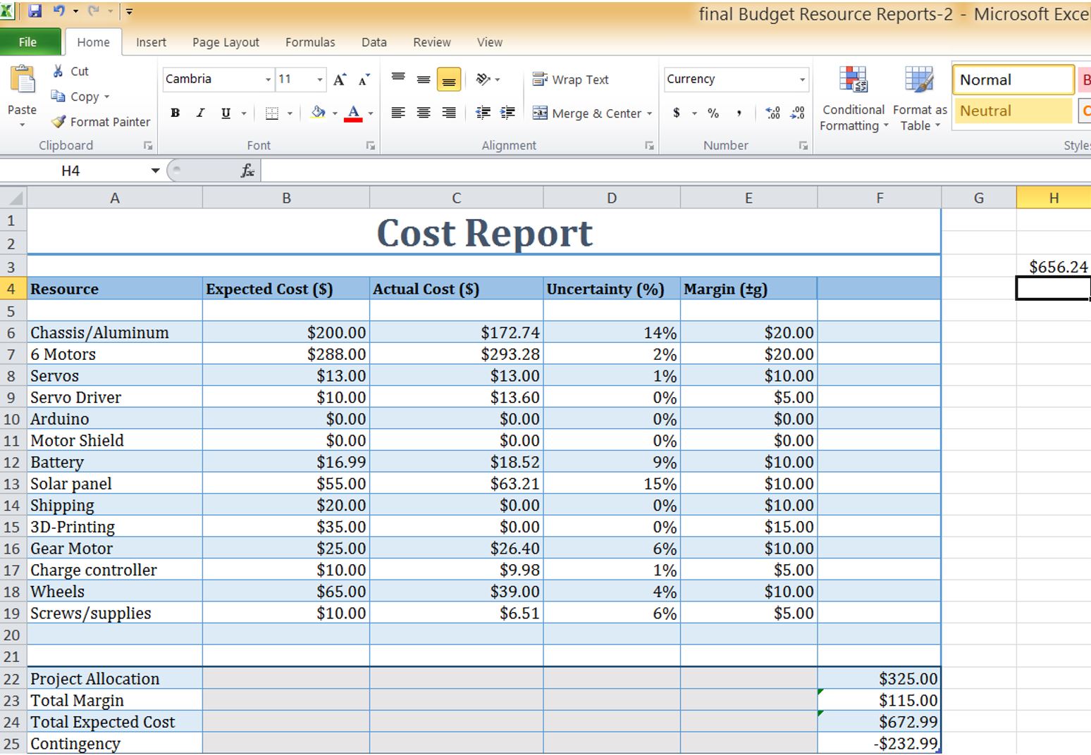
The mass report and power report are both missing because our team did not have enough time to update the reports for the new pathfinder.
For previous mass report and power report, refer to “CDR presentaion” in Project resource file
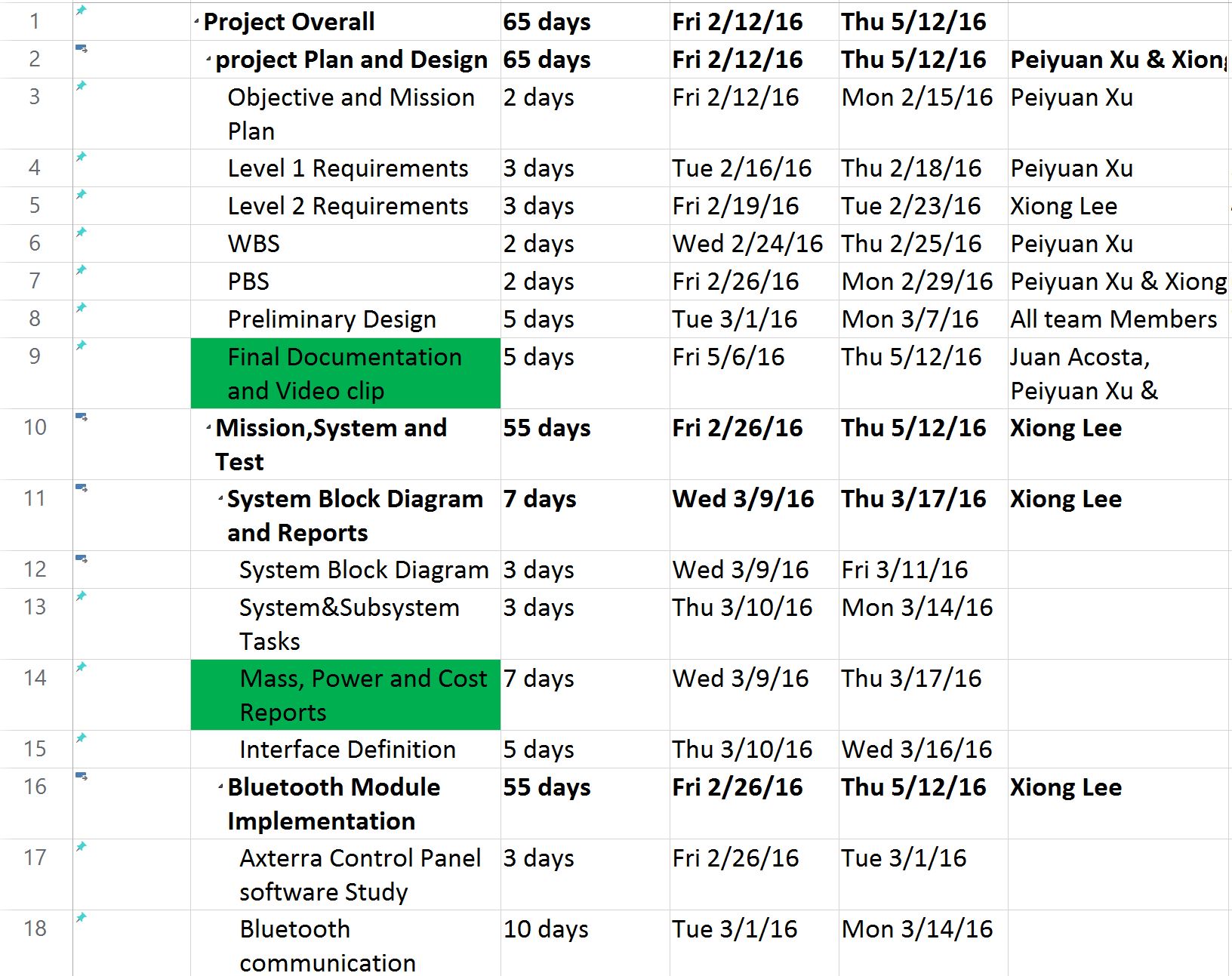
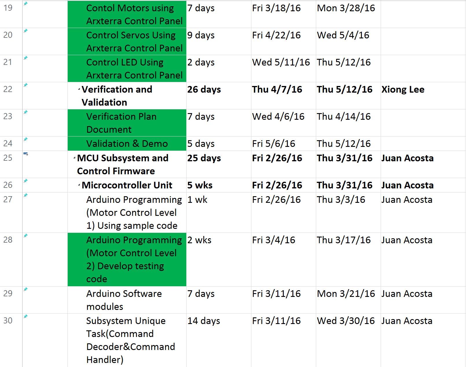

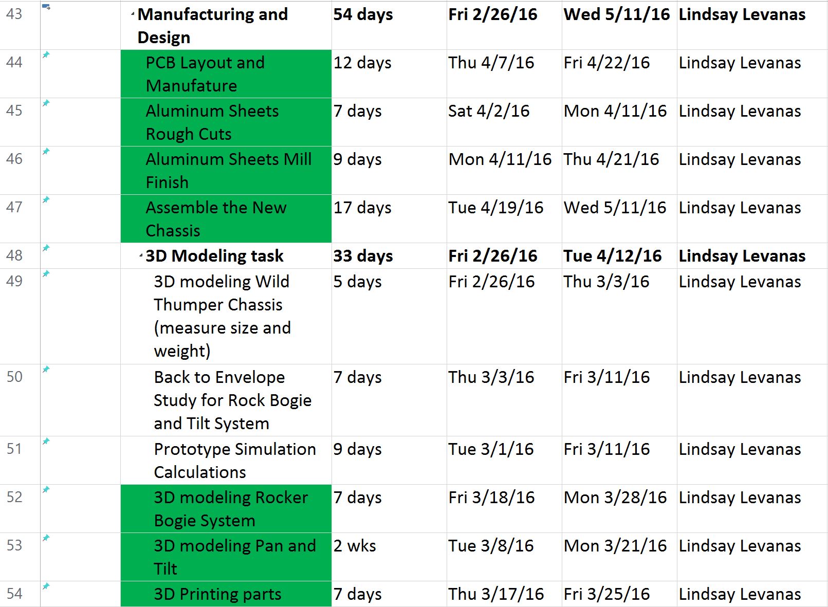
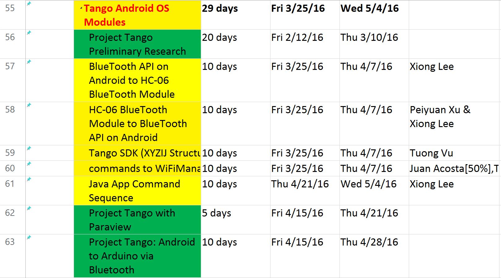
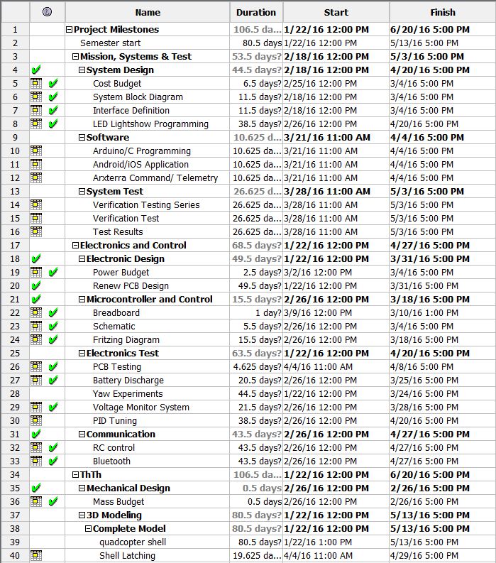
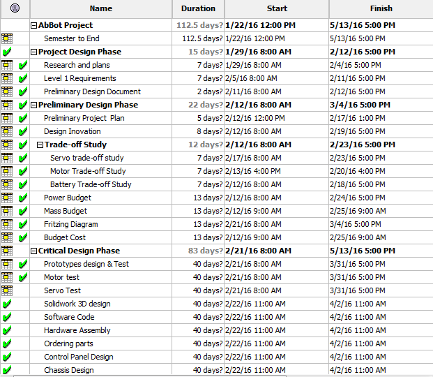
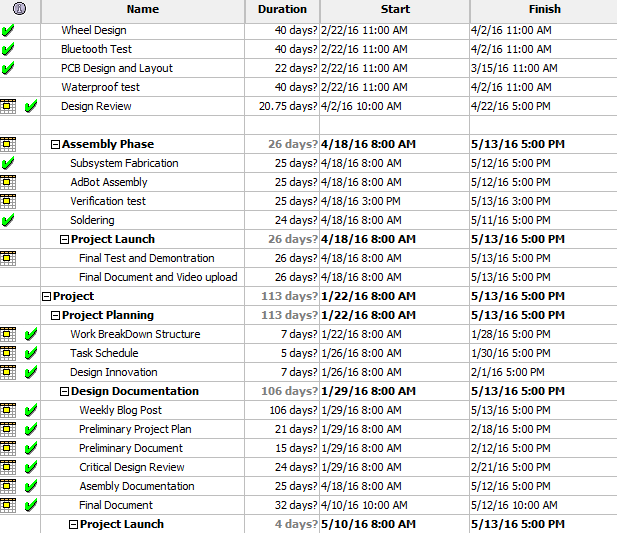
Above is the final schedule for this spring 2016 Pathfinder Rover Project. The Project Overall duration is 65 school days. This schedule was made and managed by the project manager to keep on track of the project overall progress. The tasks highlighted in green are the major tasks our team accomplished during this semester, while those tasks highlighted in yellow are the tasks our team had difficulties and could not accomplish them on time. In this semester, our team was able to fully tested, debugged and implemented the code for motors control and servos control for pan and tilt system through both coolterm and Arxterra. Another progress we made was to build a new generation of pathfinder by implementing Rocker Bogie Suspension System and solar panels self-charging capability. However, the team had troubles of implementing Project tango modules to the pathfinder.
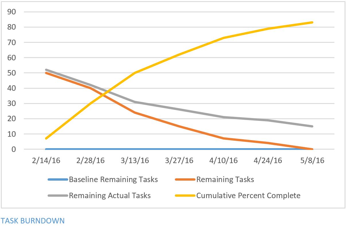
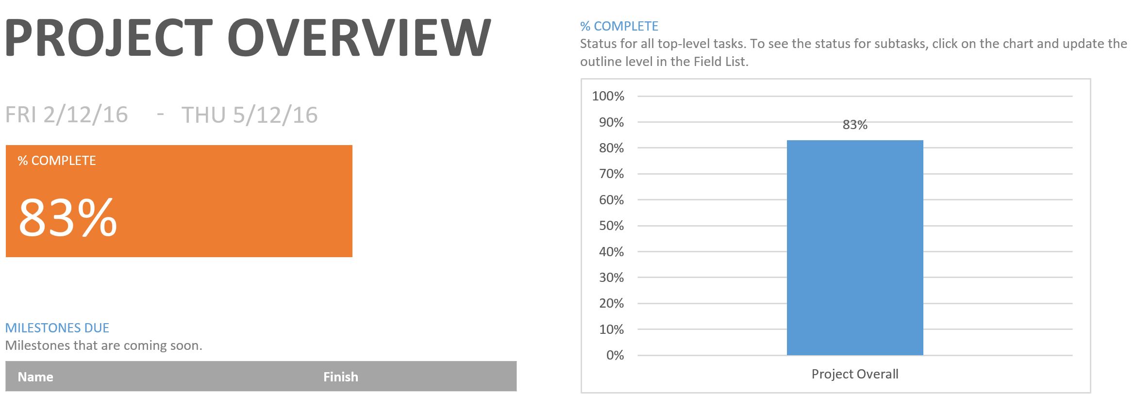
The Project Overall completion is 83%.
Verification and Validation Documents
By: Stephen Cortez (Electronics Engineer)
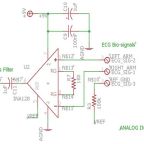
This blog post will cover the remaining two sensors that were made by the group, which includes the ECG and blood oximeter. Research concluded that commercial devices for these categories were either too large or too expensive to implement into the project, requiring custom sensors.

By Muhammad Maqbool (Manufacturing and Design)
There are many different types of material we used to finish our final design. The body and the arms of our AdBot were made of aluminum of 0.125” thickness that we obtained from McMaster. The reason for using aluminum instead of plastic was the size of our body and we wanted a strong and reliable material—something that would not fall apart. It was impossible to 3D print the body of our AdBot. Our president Ryland had access to welding tools and drill press; he helped us put the body together and did a pretty good job with it and we ended up saving a lot of money. Our major concern after the body was put together was the weight. The body is strong but it is heavy.
For our 3D printing material, we went with ABS plastic because:
Source: http://www.makergeeks.com

Luis Valdivia (Project Manager)
Juan Mendez (Manufacturing Engineer)
Anthony Becerril (Systems Engineer)
Kevin Nguyen (Electronics Engineer)
Table of Contents:
Project Overview:
These series of summaries break down all the project efforts done throughout this semester of work. This overview follows our Critical Design Review with the Debrief details here.
Executive Summary
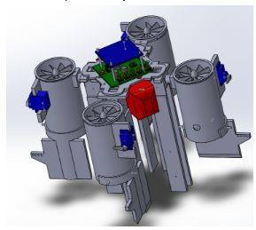
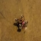
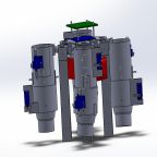
Figure 1.1 CAD Model of UFO quadcopter and thrust vectoring flaps

Figure 1.2 CAD Model of UFO quadcopter and thrust vectoring attachments
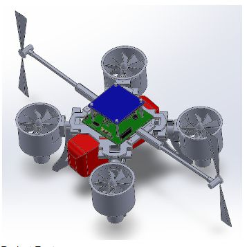
Figure 1.3 CAD Model of UFO quadcopter and additional side fans
System Design

Figure 1.4 System block diagram of UFO quadcopter Spring 2016
Experimental Results
One experiment that was done was a torque experiment. This was done in order to find the torque that the yaw problem was producing and with the results we would be able to use to counter that torque. Research was conducted to create a proper test. A torque apparatus was then built where the test was conducted. The procedure for the test and results can be found in UFO Torque Test Spring 2016.
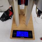
To figure out the necessary thrust from the 5th and 6th fan, we used the highest torque test reading .0515Nm along with the 6 inch fan rod and the torque formula using in physics class. Using the equation m=(Torque)/(g*radius) , we conclude m=(.0515Nm)/(9.8 *6 inches) –> m=.03448Kg is the necessary thrust counter the yaw rotation caused from the 4 EDFs. Since we used two side fans, we can set the output thrust for each fan to 17.24 grams. Using the buck converter, we turned down the voltage to produce that thrust per fan (2 fans). From the results we need to keep the output voltage from the buck to be roughly 1.91 volts to produce around 17 grams. Below we demonstrate the measure thrust values of the 5th and 6th fans with respect to different voltages.
| Voltage | Thrust |
| 2.97V | 33 g |
| 1.92V | 18 g |
| 1.9V | 14 g |
| 1.56V | 8 g |
Table 1.1 Demonstrates the relation between Voltage and Thrust for the additional side fans.
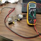
The current drain experiment consisted of a shunt resistor and a multimeter to measure the current draw. Since our motors draw large amounts of current, the multimeter was not able to take any proper measurements. To bypass this, a shunt resistor was used to measure voltage rather than current. After finding the voltage across the shunt, simple calculations can be done to acquire the current measurements. Details on this test can be found in Current Draw Spring 2016
Testing the functionality of Bluetooth vs. RC, an experiment was done by controlling the quad with each controller and incrementing the distance until connection was lost. The RC controller proved to be much more reliable and can communicate at well over 30 feet. The bluetooth communication often had trouble disarming the quad so it can’t stop the quad once things get out of hand. Information on Bluetooth Communication can be found the Bluetooth Communication: Smart Phone Applications Spring 2016 blogpost.
Details on RC Communication with the UFO can be found on our RC Control Spring 2016 blogpost.
Subsystem Design

Figure 1.5 Interface definition demonstrating ports used in the project
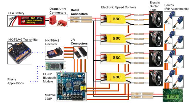
Figure 1.6 Cable Tree of overall electronics for UFO Spring 2016
Fritzing:
Since PCB fabrication is a time-and-costly procedure, a prototype must be developed to ensure that the PCB would work the first time. The first step to the prototype is the Fritzing Diagram. The Fritzing Diagram maps out all the connections of the components on a breadboard.
Physical Board:
Continuing off the Fritzing Diagram, the physical prototype is implemented on a breadboard and tested using a power supply. The power supply was set to 14.8V to simulate the battery and the output was measured to be 4.94V.
Schematic:
After the prototype was confirmed to be working, the next step is to design the schematic for the PCB. The components had to be carefully chosen to include SMD packages. The components had to be changed multiple times since those packages were not available on DigiKey. Once all the required components were on the schematic and all the connections were wired properly, the Eagle files were given to the Manufacturing Engineer to do the layout.
Layout:
After designing a PCB schematic for the project, a layout had to be done in order to have it fabricated. The board was designed to be mounted on the UFO. Components were placed properly and trace widths were modified. Once the board was laid out, it was sent to be fabricated and then it was built. Further details can be found in UFO PCB Layout Spring 2016.
Several designs were taken into consideration in order to fix the yaw problem. The original design was to implement thrust vector control. This was done by adding attachments to the electric ducted fans and which would be able to control the direction of the thrust produced using servos. Unfortunately due to some unexpected issues, the idea of thrust vector control could not be implemented. Further details such as 3D models, dimensions for the original design can be viewed in Designs of 3D Printed Attachments Spring 2016.
Since this idea did not work, an alternative solution was thought of. The next approach was to add additional fans to counter the yaw problem. This did not give us issues as the previous design did. Further details about this alternate design can be viewed in Spring 2016 5th Fan Bracket Design.
Minor modifications were done to the UFO in order to increase the space for the battery while reducing the weight. Details can be viewed in Spring 2016 Re-design of Structure Rods.
Software Design
Verification & Validation Test Plan Matrices
| Requirement Number(s) | Shall Statement | Verification Method Summary | Verification Method | Results | Pass/Fail |
| 1.1, 2.1.1, 2.1.2, 2.1.3 | UFO Ab-ducted quadcopter shall maintain stable flight for at least 7 seconds. | Quadcopter will be timed via digital stopwatch from start of flight to end of flight. Flight will also be recorded to verify flight duration. Only flights that are stable with minimal yaw rotation will be accepted. Time must be within the tolerance of +/- 0.2 seconds (time between 6.8-7.2 seconds). | Test | TBD | TBD |
| 1.2 | Project shall be completed before end of Spring 2016 semester which ends on Friday, May 13th, 2016. | Project efforts shall be completed by Friday, May 13th, 2016 therefore no more work to be done thereafter | Analysis | Project was completed at the conclusion of Friday, May 13th, 2016. All documents and efforts were completed at the end of this day | Pass |
| 1.3, 2.3.1 | UFO Ab-ducted quadcopter shall comply by rules and regulations of the Federal Aviation Administration (FAA), Unmanned Aircraft Systems (UAS), and California State University, Long Beach’s College of Engineering’s flying policies. | To fulfill compliance of FAA, UAS and CSULB COE, the quad copter shall be registered as a flying object and shall not break any rules and regulations | Inspection | quadcopter is officially registered. It was registered under the identification number FA3C74WXLT. It also abides by the rules and regulations such as: | Pass |
| 1.4 | Budget for this project shall remain below provided budget of 167 U.S. Dollars | Shall have approved budget with evidence via reciepts with the total cost lower than the provided budget | Analysis | Budget was submitted and approved at a total of $156.34 with supporting documents and information to complete the reimbursement process | Pass |
| 1.5, 2.5.1 | UFO Ab-ducted quacopter shall feature a light show of at least 3 unique patterns. | The lightshow shall be displayed and while on display is to give at least 3 unique patterns | Inspection | TBD | TBD |
| 1.6, 2.6.1, 2.6.2 | The UFO Ab-ducted quadcopter shall be capable of control with wireless communication for a range of at least 10 feet. | The wireless communication will be setup and tested with increasing distances away from the quadcopter being recorded | Test | TBD | TBD |
| 1.7, 2.7.1 | The UFO Ab-ducted quadcopter’s Printed Circuit Board (PCB) shall power at least one servo at 5 five volts via a buck converter. | Each pin and component on the PCB will be tested to give the 5 volts from the battery/voltage source. | Test | TBD | TBD |
Table 1.2
| Requirement Number | Objective | Validation Method Summary | Validation Method | Pass/Fail |
| 1.1, 2.1.1, 2.1.2, 2.1.3 | UFO Ab-ducted quadcopter shall maintain stable flight. | Customer will evaluate stable flight of quadcopter. | Demonstation | |
| 1.3, 2.3.1 | UFO Ab-ducted quadcopter shall comply by rules and regulations of the Federal Aviation Administration (FAA), Unmanned Aircraft Systems (UAS), and California State University, Long Beach’s College of Engineering’s flying policies. | Customer will observe registration number and paperwork. | Inspection | |
| 1.4 | Budget for this project shall remain below provided budget of 167 U.S. Dollars | Customer will observe and confirm budget paperwork. | Inspection | |
| 1.5, 2.5.1 | UFO Ab-ducted quacopter shall feature a light show of at least 3 unique patterns. | Customer will observe lightshow. | Inspection | |
| 1.6, 2.6.1, 2.6.2 | The UFO Ab-ducted quadcopter shall be capable of wireless communication. | Customer will observe wireless communication via RC and bluetooth. | Demonstation | |
| 1.7 | The UFO Ab-ducted quadcopter’s PCB shall power at least one servo via buck converter. | Customer will observe servo powered via PCB servo driver. | Demonstation |
Table 1.3 Validation Matrix with requirements, objectives, and summaries
Project Update

Figure 1.7 Work Breakdown Structure for the engineers in each division

Figure 1.8 Resource report referring to Mass report for UFO Spring 2016

Figure 1.9 Resource report referring to Power report for UFO Spring 2016

Figure 1.10 Resource report referring to Cost report for UFO Spring 2016
The project schedule was documented using, Project Libre. Every task was listed under each engineering division to display the engineer responsible for each task.


Project Demonstration
Project Blog Posts
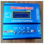
Lipo Battery Safety Spring 2016
This post is a step by step guide on how to use the LiPo charger. Failure to handle the LiPo in a safe manner may result in damaged batteries….or worse self injury to user.
PCB Design: Schematic – Spring 2016
This blog post includes full detailed explanations on the components used within our PCB. Images of the components on Eagle Schematic are posted above each paragraph to give the reader a better understanding. Full schematic image is provided to show the connections between each component.

Current Draw Spring 2016
High powered motors are difficult to measure with a multimeter since the current draw exceeds the specifications of the meter. This post explains how to measure the current draw by measuring the voltage and resistance instead.
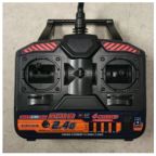
RC Control Spring 2016
RC control is a must for quadcopters since bluetooth is short-ranged and unreliable. This post will guide the user through setting up the transmitter and receiver as well as setting the proper configurations on the MultiWii.
Prototype: Fritzing and Breadboarding – Spring 2016
To ensure that the PCB works the first time, a prototype is needed to test the functionality of the circuit. This blogpost overviews the process of creating the prototype circuit.
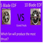
Spring 2016 Trade off study: 5 Blade EDF vs 10 Blade EDF
This blogpost compares the different thrust outputs from 5 Blade EDFs and 10 Blade EDFs. We demonstrate different throttle positions on our RC controller which correspond to different thrust from. We will finally see which fan is the strongest!
UFO Mass-Thrust Trade Off Studies Spring 2016.
Trade off studies were performed in order to determine how much weight the UFO can have before it got too heavy to lift off. An equation was found which allowed us to calculate the max weight. In order to confirm this equation with the UFO weight, servos, 3D printed attachments were added on.
Bluetooth Communication: Smart Phone Applications
Going over communication and controls, this post summarizes the smart phone applications used to receive data from the quadcopter flight controller sensors as well as use other applications to control the quadcopter rather than RC control.
Bluetooth Module Update Spring 2016
This details the bluetooth modules used previously and the new one implemented moving forward in series with the MultiWii flight controller and its GUI.
Verification and Validation Matrices Spring 2016 UFO
As detailed on the verification matrix, the following requirements have their own pass/fail results detailed:
1.1 – Stable Flight
1.2 – Project Completion
1.3 – FAA, UAS, CSULB COE Compliance
1.4 – Project Budget
1.5 – Lightshow
1.6 – Wireless Communication
1.7 – PCB
UFO Spring 2016 – EDF Area Coverage With Flap Length Calculations
We performed some calculations to determine the size of the allowable flap length on our EDFs. Using Microsoft Excel, we were able to determine an array of sizes with their corresponding output thrust.
Using Multiple servos without servo driver UFO spring 2016
As a way of rapid prototyping our system without a servo driver, we wrote a blogpost to show an alternative to controlling servos. This method involves a simple wiring diagram with example code for various methods.

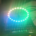
UFO Light Show Setup
The Neopixel ring is the aesthetic cornerstone of our wondrous quadcopter. This blogpost shows how to setup the hardware and software for the lightshow.
Project Preliminary Design Spring 2016 Millennium Falcon
This is our continuing on our research blog post which together is known as our Preliminary Design Review. It outline the beginning of all our work and sets up our fundamental understanding of project moving forward.
Spring 2016 Millennium Falcon Research
This post is an outline of our research of past quadcopter projects and possible solutions for approaching these solution.

Spring 2016 Millennium Falcon Preliminary Design Document
A Preliminary Design was put together for presentation by all group members. Here Program objective, Level 1 and 2 Requirements were defined along with Product Breakdown structures and project designs. Further details about the sections mentioned can be found in Spring 2016 Millennium Falcon Preliminary Design Document.

Concluding Thoughts:
Improvements for next semester:
Lessons learned:
Things we could have done different:
Project Resources:
To best complete the transitioning of this project for future students, a resources folder was compiled into a Google Drive folder. The access to this folder is here: https://drive.google.com/folderview?id=0B5GCeIa4TgwtNjM0VXBoNTBTWDg&usp=sharing
It is best to read the “UFO_SP16_AResourceSummary” document and following through with all the additional, provided documents in the resources folder and get up to speed on the project’s progress.

Posted by: Luis Valdivia (Project Manager)
Written by: Anthony Becerril (Mission, Systems, and Test Engineer)
Following the Verification and Validation Matrices, this post follows the level 1 requirement 1.5 – designing and implementing a lightshow to display at least 3 unique patterns. This also satisfies its corresponding level 2 requirements if applicable.
To meet the requirement, the use of the NeoPixel LED Ring had to be implemented into the quadcopter and designed to properly work through the Printed Circuit Board (PCB) and display at least 3 unique patterns. Following the previous post on the lightshow, The lightshow properly works and has been emulated successfully. Next, through use of our PCB, the LED ring is to be powered and programmed to display the lightshow. The PCB was unable to produce the light show emulated before due to the problems of going through I2C. Supporting documentation is provided below and we have completed and failed this requirement.
Additional Resources:
Previous Blog Post: Verification and Validation Matrices (Spring 2016)

AdBot is a robot that can drives around campus in place of a person passing out flyers.
Dang Le (Project Manager, Electronics and Control)
Don Tran (Mission, Systems, and Test)
Muhammad Siddiqui (Manufacturing and Design)
Table of Contents
Program Objective
The project objective is to build a rover that will simulate a flyer distributor advertising CSULB’s Eta Kappa Nu social, guest speaker, and technical events on campus. Using a single power source the rover will launch from, and return to, an HKN advertisement booth and run in a general high foot-traffic area on campus which consists of flat areas, sloping areas, and stair ways, as shown in the course map. The rover will be controlled remotely using a computer with internet connection. Negotiations of budget resulted in the rover to cost less than or equal to $250. There is to be expected 0 to 16 mph wind during the course run on May 13th (Reported in Weather Report) [1].
Mission Profile
The perimeter of the grass is 275 ft / 84 m. The north and south sides are leveled. The east side has 9 steps. The west end is a ramp.
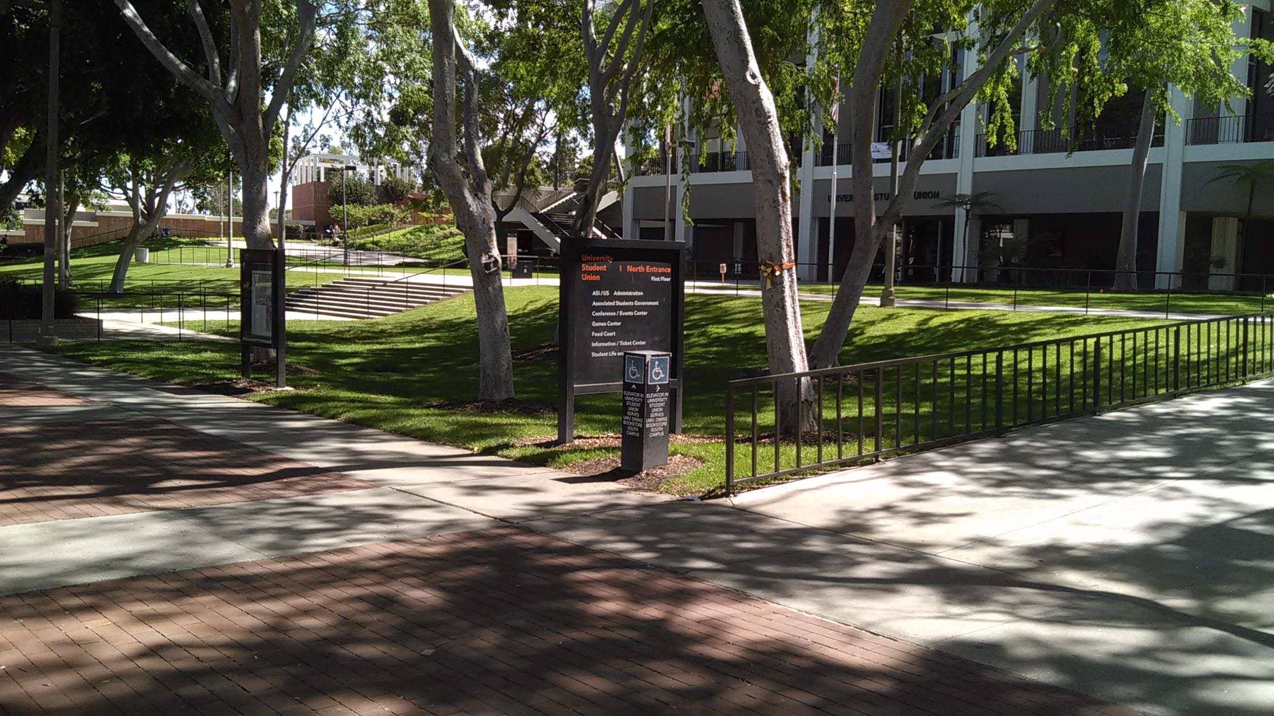
Figure 1 Test Course
Level 1 Customer Requirements
1.1 AdBot shall travel at 4.55 ft/s at the pace of an individual delivering flyers.
1.2 AdBot shall follow CSULB Regulations for Activities and Advertising.
1.3 AdBot shall launch from the HKN booth and return.
1.4 AdBot shall operating with one power source.
1.5 AdBot shall be controlled remotely through Arxterra Control Panel.
1.6 AdBot shall go up nine steps of a staircase.
1.7 The budget shall be $250
1.8 AdBot shall protect its hardware from weather conditions on the day of the final.
Level 2 Requirements
1.1 AdBot shall turn at 84 rpm.
1.2 AdBot’s sign holder shall be within 3 ft.
1.3 The course shall be completed in 8 min.
1.4 AdBot’s current draw shall require 1000 mAh.
1.5 The Arxterra app can connect via bluetooth within 3 ft.
1.6 AdBot shall provide 25 kg-cm torque to straighten out.
1.6 The sign shall be 5.3 in. from the back of the chassis.
1.6 AdBot shall not bend at the motors or servos due to weight.
Design Solutions
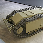
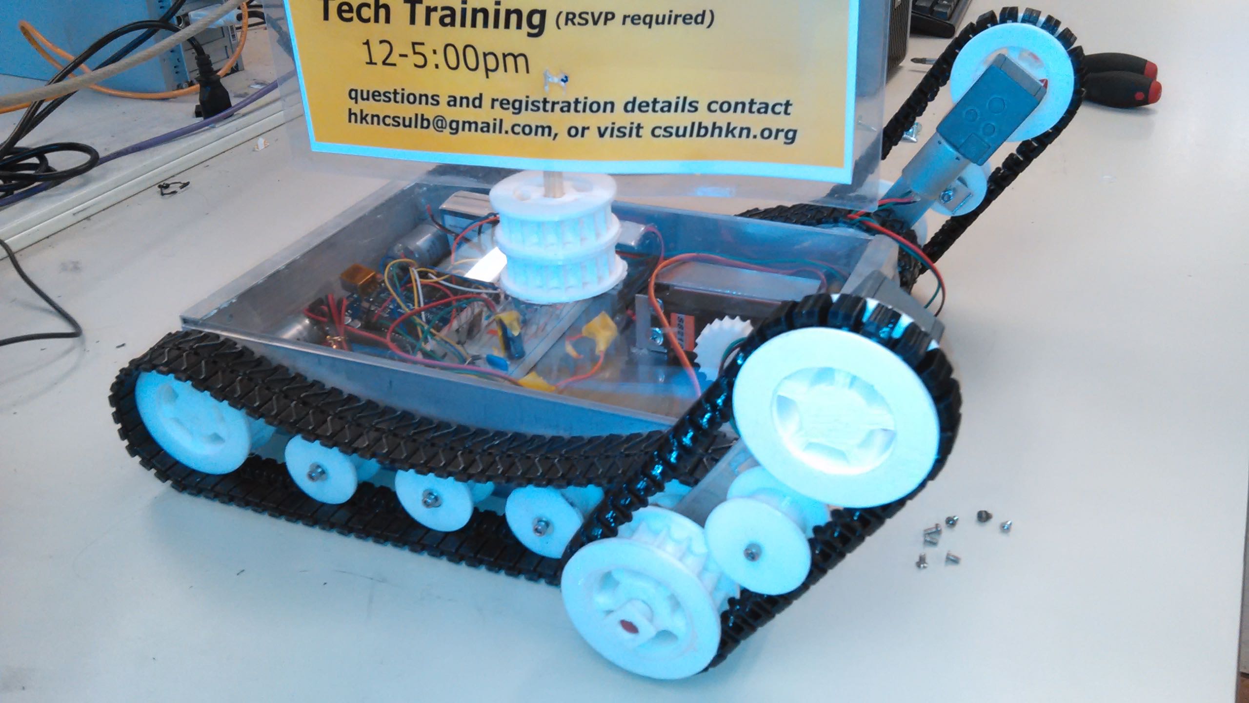
Tracks instead of wheels make AdBot look military. They can drive over obstacles on the ground without getting stuck.
For the PDR, the chassis was built out of wood and 3D printed wheels. The 3D printed tracks had more tension in hopes that they do not fall off. The wheels had longer treads. AdBot was powered by battery. It moved with differential drive control and could drive forward, backwards, and turn. The tracks shifted on the wheels. The servos moved using an unsigned byte, slider from 0-90, custom command in Arxterra.
For the CDR, the chassis was built out of 6061 aluminum. The wheels were reprinted and prevent the tracks from undoing. The left side tracks moved together; the same goes for the right side.The motors were switched to higher torque ones and changed from 6 V to 12 V. Without a battery yet, AdBot was powered with a AC to DC wall adapter and wire. The geared motor to lift the arms was not finished.
Motor Driver Trade-Off Study
The Arduino pins supply less than 0.040 A. The solution to drive motors is to find motor drivers. The trade-off study is in this link here.
Motor Trade-Off Study and Torque Test
DC motors are commercially available and offer choices. The motors have gears that changes thousands of rpm into hundreds. The motors of interest offer more torque force with decreasing speeds. Several motors are purchased and tested as stores do not claim the torque information or stall current. This link link has information.
Experiments
AdBot was taken to lab equipment to measure the motor specifications. Free multimeters have a 0.020 A limit. The torque test apparatus was used on motors. 1K, 5K, 10K, and 20K potentiometers could not stall the motors. The motor shafts were held onto a bearing by a screw and the bearing was attached to a wheel. This was done in order to provide grip to cause stalling. More information is here .
PCB Design
The custom PCB is a shield that fits on top of the Arduino Uno. It contains motor drivers to supply current to five motors. It features an HC-06 bluetooth module. The layout and schematic are in these links here and here. We made a through-hole PCB, but had to remake it into surface mounted.
Arduino Software Code Design
The firmware folder has many files containing multiple functions. The commandDecoder receives information from the Arxterra app in the form of a command packet and authenticates it. It will then pass the data packet to commandHandler to distinguish out if this is a move operation or camera-related operation and whatnot. The Arduino code then passes the packet to a function that will work on it. move_TB6612FNG() receives a packet for driving. The code is in this link here.
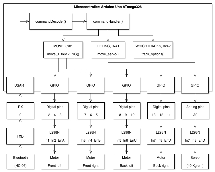
Software Block Diagram
Interface Matrix Definitions and System Block Diagram
A system block diagram and interface matrix are available so that this project can be replicated. They show the components that are used and wire connections. AdBot’s interface matrix begins displaying all the Arduino Uno’s pins and names. Components are placed in columns. When an Arduino pin is not vacant anymore, the row turns white to indicate that the next component cannot place a jumper lead in the white box. The table and diagrams are in linked here.
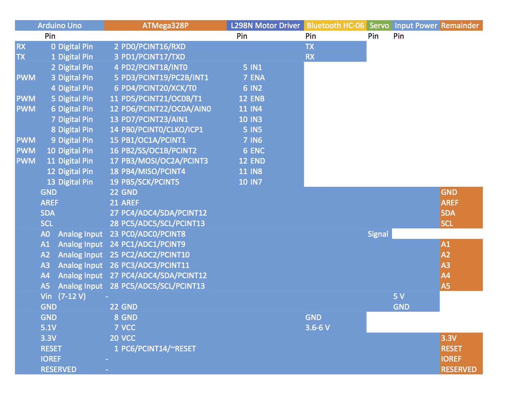
Interface Matrix Definition
Hardware Design
There are many different types of material we used to finish our final design. We wanted to use strong and reliable materials. Material trade-off study is described in this page here.
Our project manager worked on the schematic and the manufacturing engineer put together the layout. One of the problems our manufacturing engineer faced while doing the layout was the positioning of the pins that will be connected directly to the Arduino Uno. Information about the custom PCB manufacturing is in this link.
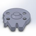
Start out with understanding the basic design of AdBot. It consists of a total of eight big wheels, eight tension wheels, four tracks, two gears, one wooden shaft, one wooden pole, one pole holder, and one flat top. The design for the wheels and tracks are from previous semester’s RoSco. I modified them so that they work for AdBot requirements. Details about designing in SolidWorks is here.
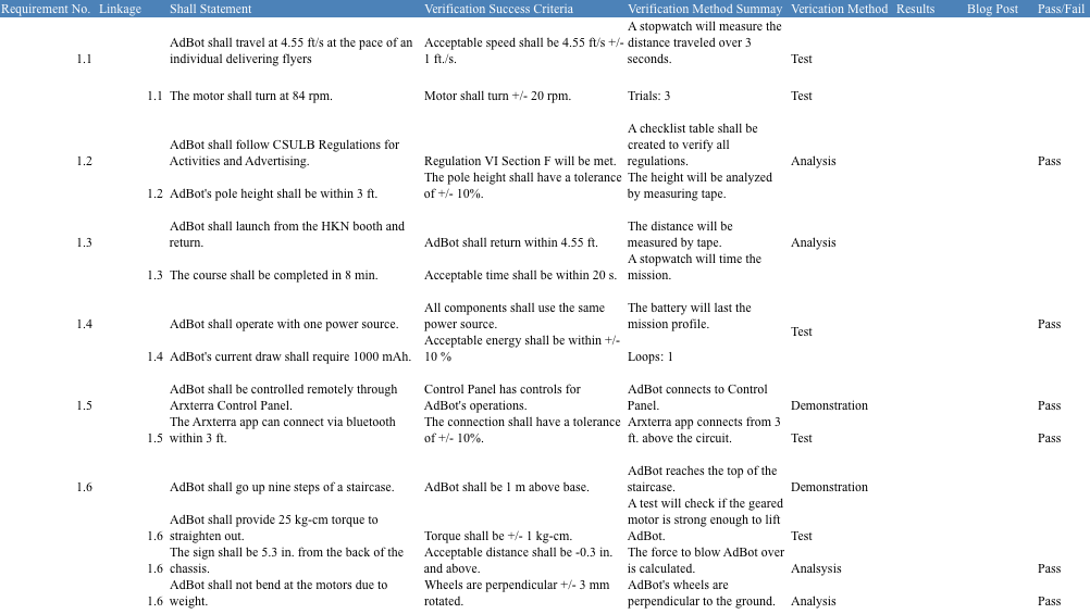
Verification Test Plans
AdBot’s performance depends on the test plan. These plans show the requirements were considered and are kept when constructing AdBot. The table is linked here.
Validation Test Plans
The customer looks at qualitative features of the product built. Validation tests are done on the day of the final demonstration. The table is linked here.
![]()
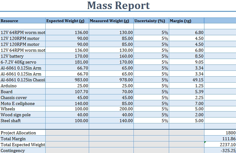
Mass Budget
Knowing individual masses lets the manufacturers know what components or materials to take out or replace. The allocated mass is based on the overall masses to stall the drive motors.
Power Budget

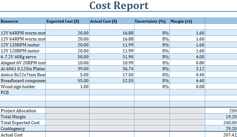
Cost Budget
The construction of AdBot rover received a $250 budget. After the first few weeks, $100 was spent on breadboard parts and the chassis. The team has to keep track of our budget during the time building the project. Luckily we saved money and time on shipping due to our team purchasing Amazon prime. The project ended up with approximate $208 of spending—not including the PCB fabrication and SMD components. The cost of the end product is shown.
Project Libre was used to schedule the semester. The WBS illustrates the members’ duties in the schedule and pace to complete those. The depictions are shown
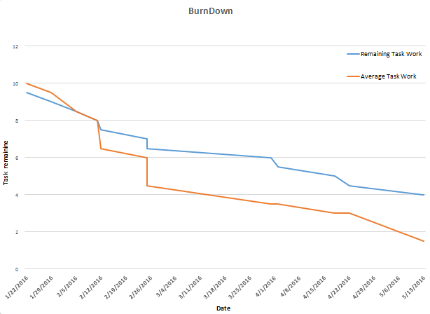
The burndown line will not reach zero in software.
AdBot is designed after a tank, and it is built from the ground up on a $250 budget. We ordered several parts from China to save several dollars. This mistake delayed our project for the CDR presentation. We spent a lot of our money during the design phase too on tools and parts to learn to use. With four weeks left and no electronics engineer to make a new schematic, the systems engineer, manufacturing engineer, and I worked extra overtime. The systems engineer had a difficult time writing and troubleshooting his C++ functions that receives commands from the Arxterra application. I was busy a lot in the project, because having one person working on manufacturing is not enough. Construction requires multiple heads to check, cut, drill, and build correctly. Everyone worked on software and tasks almost everyday for months.
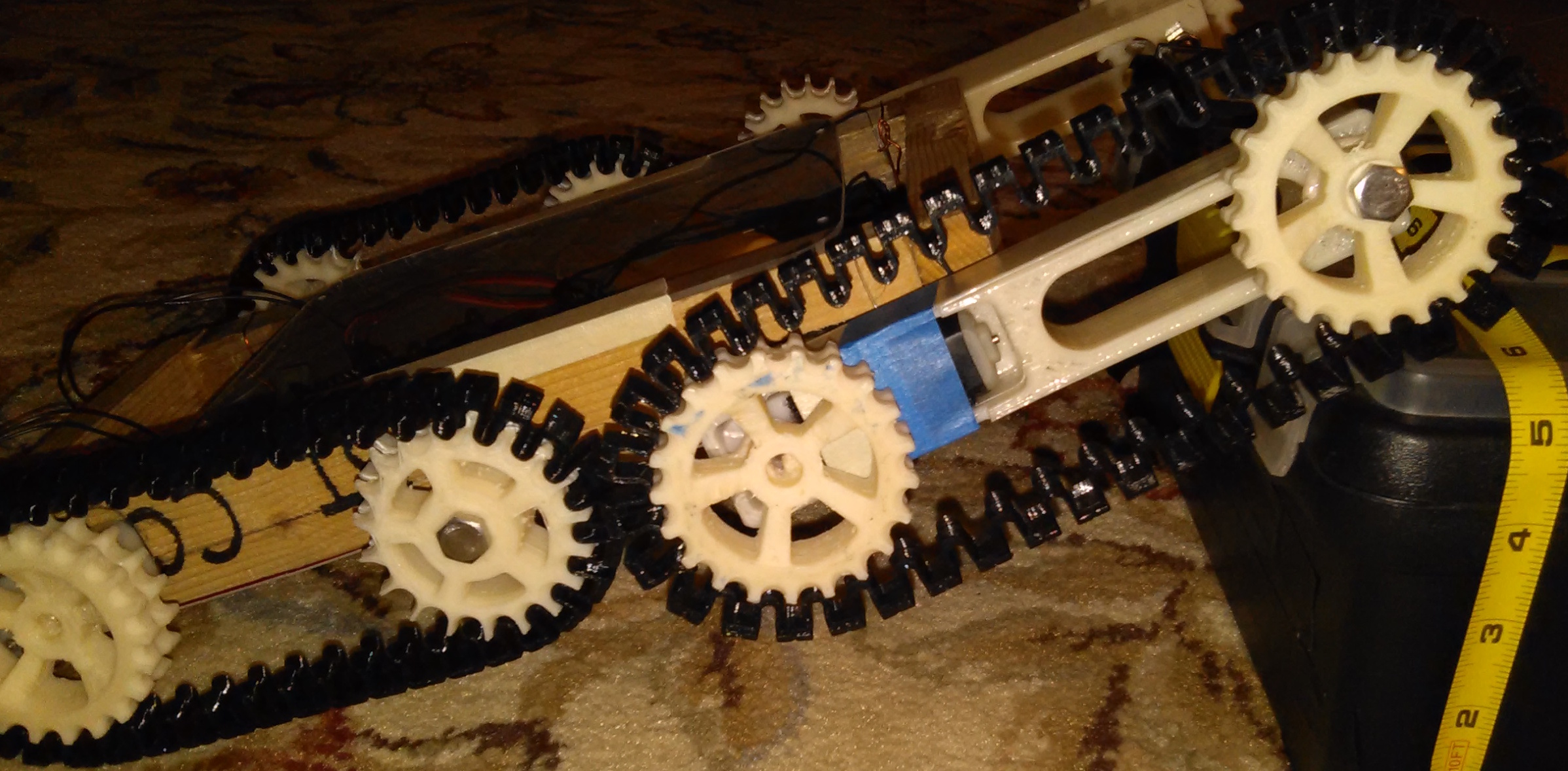
The front motors at the end of the arms on AdBot are heavy. It places enough tension on the shaft to shake the servo around, which is screwed onto brackets. In this situation, the president helped us mount the servo securely. To make AdBot better, we should move the motors inside the chassis to drive the four front wheels. The tracks are too long to print on certain machines. The printed tracks took a long time to work on, but after printing, they do not come out as expected. On the final, we used metal tracks.
The system and software block diagrams are created using the full version of Shapes.
Verification & Validation Table

By Dang Le (Project Manager)
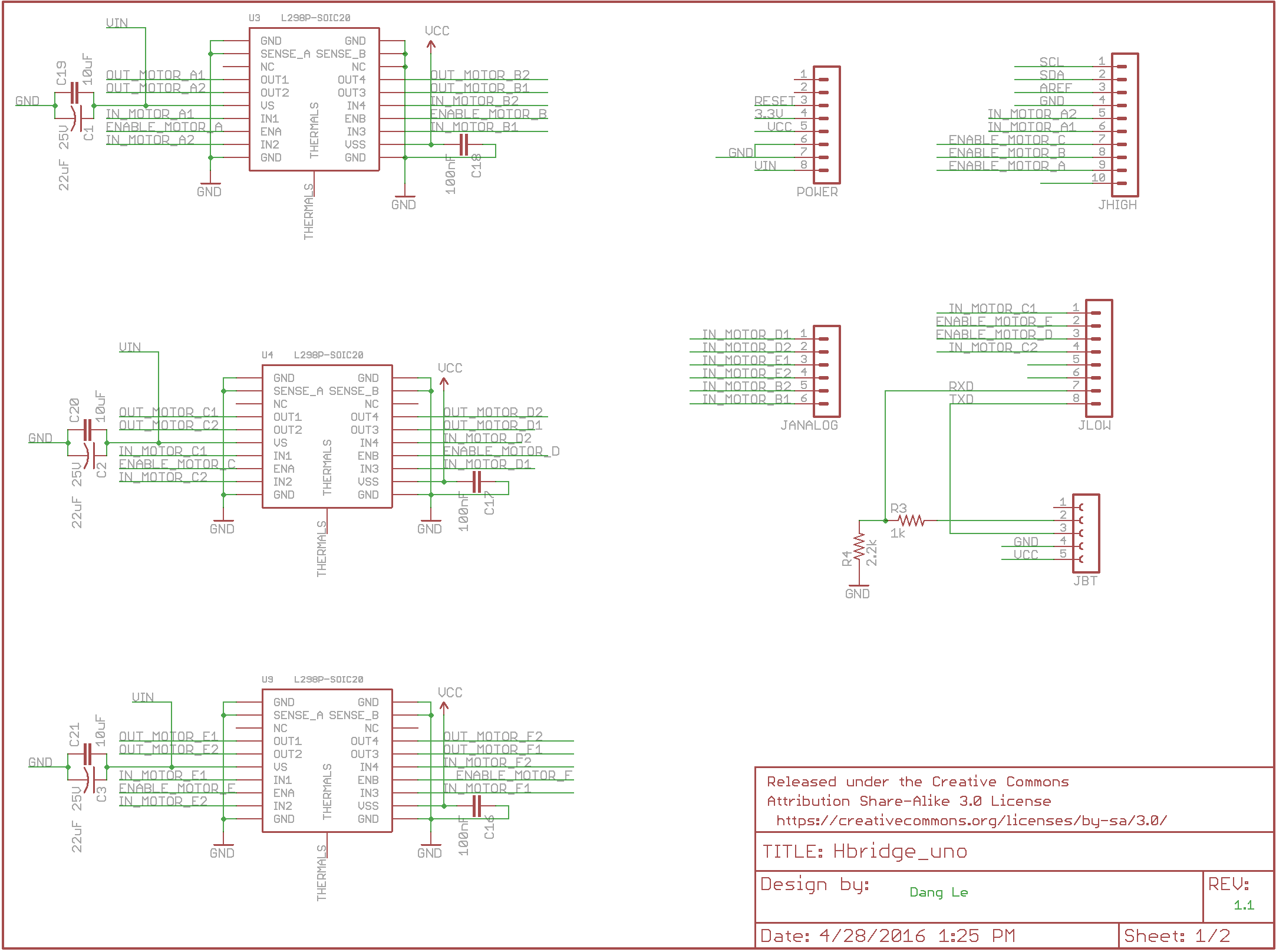
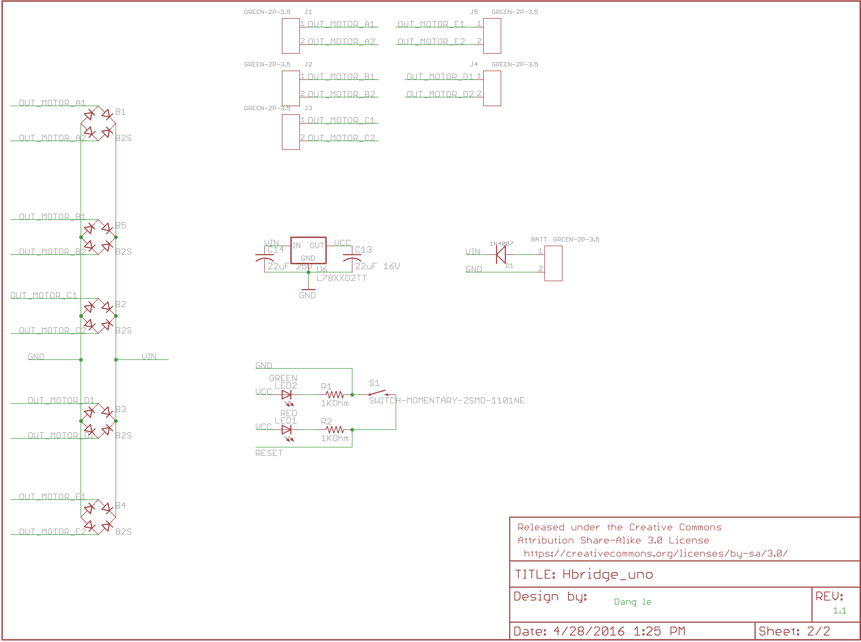
The PCB schematic for AdBot, made by the project manager, in figure 1 shows pin allocations with the integrated circuit components and the Arduino Uno.
Schematic page 2
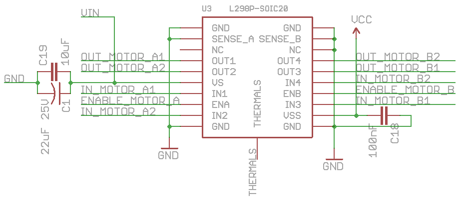
Figure 2. L298P motor driver.
The first L298P half bridge is the surface mount PowerSO20 component, which is not the Multiwatt15 breadboarding type so the pins read differently. The sense pins are grounded. They are not connected to 0.5 ohm 2 watt resistors for measuring the voltage and current draw. The device is manufactured with two no connection terminals. Vs requires inputing the power source, which is a 12 V battery. Vss is for inputing 5 V to keep power for logic.
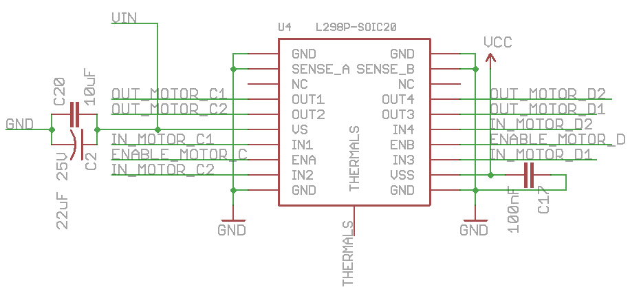
Figure 2. L298P number 2.
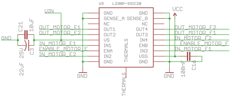
Figure 3. L298P number 3.

Figure 4. Arduino Uno pins 8 and higher.
The above image shows the header connection to the Arduino and the roles some pins are designed to have. Each half bridge has runs two motors, so they have a total of four input and two enable pins to connect to the arduino. JHIGH refers to pin number 8 up to SCL.

Figure 5. Arduino Pins 1 to 7.
The above image shows the the remaining pins. JLOW represents Arduino pin number 1 to 7. The voltage divider connections to the bluetooth module. Analog pins are used to write digital highs and lows to the motor driver just as digital pins are capable of doing.
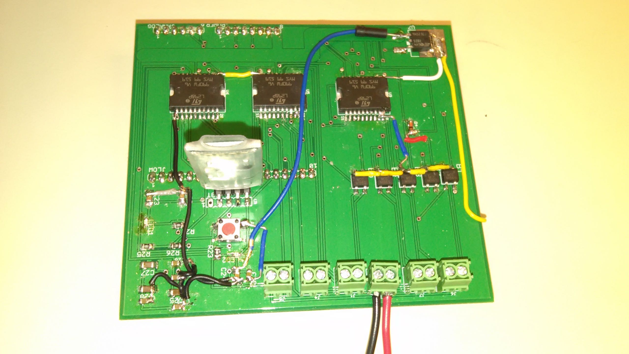
The project manager worked on soldering and troubleshooting the PCB board. He measured and tested the board for problems.

By Muhammad Maqbool (Manufacturing and Design)
Dang Le (Project Manager)
PCB layout was one of the hardest tasks to complete. We were left with no schematic. Our project manager worked on the schematic and the manufacturing engineer put together the layout. One of the problems our manufacturing engineer faced while doing the layout was the positioning of the pins that will be connected directly to the Arduino Uno. The dimensions for the pin placement were found online while keeping in mind the distance between Jlow and Analog should be 1.9”. The motors are placed on the right edge of the board so it is easy to connect or disconnect wires. All the capacitors are placed on the bottom right of the board so it is easy to put the components when the PCB arrives. We were not sure about the placement of the half bridges so the manufacturing engineer double checked it with the president and we ended up placing it between the pins that will be connected to the Arduino. They are kept close to the power source. For routing first I made a power bus of 0.18” and dragged it all the way down and then manually routed all the components that will be getting direct power from it. All the remaining wires are 0.016” thick. Source

Figure 1. PCB layout