Spring 2018: Biped Micro FOBO Final Blog Post

By: Miguel Gonzalez (Project Manager)

Approved By: Miguel Garcia (Quality Assurance)

BiPed Team:

Miguel Gonzalez (Project Manager)

Jeffery De La Cruz (MST)

Jorge Hernandez (E&C)


Table of Contents

Mission Objective

By: Miguel Gonzalez (Project Manager)


Goal for this project is to design and manufacture a BiPed Robot. This robot will be slightly similar to the BiPed robot that was created in Spring 2016 and another bipedal robot named FOBO, created by Jonathan Dowdall. Our design will be based on FOBO but will be much smaller in size that implements micro servos for walking and turning. For sensing its surroundings, the robot will utilize ultrasonic and Infrared sensors. Other key differences between the FOBO and our micro version of FOBO are that:

  1. The head of our robot shall house a 3DoT board, servos controller shield, and a sensor shield.
  2. The movement of our robot will be conducted via SG90 micro servos that will replace the clunky and oversized Hitec HS-805BB servos.
  3. The legs of our robot will have a more efficient method to mount and utilize its servos for weight reduction and for longer walking steps.
  4. Our robot will utilize Bluetooth technology for user to robot communication and movement control
  5. The robot’s power system will be changed from heavy LIPO batteries to a single Samsung 18650 battery located near the robot’s center of mass.

The mission of Project BiPed is to design the BiPed to navigate a predesigned maze. The BiPed shall be able to navigate the maze with user input from the Arxterra App/Control Panel. The BiPed will be able to memorize the user-defined path and will be able to navigate it autonomously. In addition, the BiPed will acknowledge other robots while traversing the maze and avoid collisions using its sensors. To learn more about the mission objective you can take a look here. For preliminary maze designs and definitions take a look here.

Project: Level 1 Requirements

By: Jeffery De La Cruz (MST Engineer)

Verified By: Miguel Gonzalez (Project Manager)


Will:

L1-1: Micro FOBO will stand on its own without any physical help.

L1-2: Micro FOBO’s electronic components will be easily assembled and disassembled.

L1-3: Micro FOBO will have 2 legs.

L1-4: Micro FOBO will be a toy robot based on the design of the FOBO by Jonathan Dowdall.

L1-6: Micro FOBO will fit within the classroom cabinets shelves. 28”x13”x14.5”

L1-7: Micro FOBO will utilize a 3DoT board or Sparkfun Pro Micro 3.3V/8MHz.

L1-8: Micro FOBO’s part components will be 3D printed using the material carbon fiber PLA.

L1-9: Micro FOBO will not exceed a print time of 7.80 hours. Upon approval of the waiver.

Shall:

L1-10: Micro FOBO shall not exceed a cost of $250 to construct.

L1-11: Micro FOBO shall be 60% or less of the overall size of Jonathan Dowdall’s FOBO

L1-12: Micro FOBO shall detect intersections in the maze.

L1-13: Micro FOBO shall be able to perform static walking.

L1-14: Micro FOBO shall produce 90 degrees turn.

L1-15: Micro FOBO shall be guided through the maze with the use of the Arxterra application.

L1-16: Micro FOBO shall record the path of the maze.

L1-17: The Micro FOBO shall traverse the maze using the recorded path.

L1-18: Micro FOBO shall be able to traverse cloth, paper, and linoleum materials.

L1-19: The Final Biped shall be completed by May 10th, 2018.

Should:

L1-20: Micro FOBO should step over a square rod 1cm tall, 1 cm wide by 10 cm long

L1-21: Micro FOBO should be able to perform dynamic walking

System/Subsystem: Level 2 Requirements

By: Jeffery De La Cruz (MST Engineer)

Verified By: Miguel Gonzalez (Project Manager)


Will:

L2-1: Micro FOBO will be connected via Bluetooth to the app on an android phone.

L2-2: Micro FOBO dimensions of the robot will need to be small enough to fit in a 4in by 4in box for maze purposes.

L2-3: Micro FOBO will use SG90 micro servos.

Shall:

L2-4: Micro FOBO shall use UV/IR sensors to detect intersections.

L2-5: Micro FOBO shall use the color of the maze to establish if it needs to turn. black (0,0,0) green (0,255,0) for line following.

L2-6: Micro FOBO shall use a battery that outputs 3.7V nominal.

L2-7: The user shall use the Arxterra application to move the robot forward, backward, left, and right.

L2-8: Micro FOBO connectors shall be able to connect and reconnect all the wiring in less than 10 min.

L2-9: Micro FOBO wiring shall be nice and clean with the use of terminal blocks, contact pins, 2.0mm PH series JST connectors, and barrel connectors.

L2-10: Micro FOBO shall play a musical tune when the maze is completed.

L2-11: Micro FOBO shall have indicating LEDs to demonstrate either a left or right turn.

L2-12: The Micro FOBO shall record the path of the robot on the 3DoT board or the Sparkfun Pro Micro 3.3V/8MHz to navigate the robot through the maze.

L2-13: Micro FOBO shall use a 3D printed chassis and leg components.

L2-14: Micro FOBO shall measure within 4.5” x 3.25” x 7.25”.

L2-15: Micro FOBO shall weigh no more than the allocated mass of 460g.

L2-16: Micro FOBO shall detect objects 8 inches from it.

Should:

L2-17: Micro FOBO should be able to see other robots to avoid a collision. The robot will stop completely and wait for clearance. (Ultrasonic sensor)

L2-18: Micro FOBO should take a bow at the end of the maze as a victory celebration.

System Block Diagram

By: Jorge Hernandez (E&C Engineer)

Verified By: Miguel Gonzalez (Project Manager)


After looking at all the constraints and requirements for the robot our group came up with a system block diagram that could help us visualize how the robot’s components interacted with one another. This diagram made it clear to understand where initial designs should be made and provided great insists on some challenges we would have in the future. Below we link the blog post to the system block diagram the group made.

Work Breakdown Structure

By: Miguel Gonzalez (Project Manager & Manufacture)


When working on a team project it’s important to break down the project into general tasks and assign them to team members. Typically a chart is created to easily visualize how the work is divided among team members, this called a WBS (Work Breakdown Structure). Here we link to our post demonstrating and explaining our WBS.

Product Breakdown Structure

By: Jeffery De La Cruz (MST Engineer)

Verified By: Miguel Gonzalez (Project Manager)


Fig.1 Product Breakdown Structure

Based on System Block

Sensor Suite

  • The color sensor will be able to detect colors and its data input range Ex, black (0,0,0) green (0,255,0) for line following.
  • Will be able to see intersection sign on the maze and differentiate its color from the path lines.
  • Shall be able to see other robots to avoid a collision. The robot will stop completely and wait for a command. (Ultrasonic sensor/IR)
  • The robot should have to indicate LEDs to show where the robot plans to make a turn (left or right)

Smartphone App

  • Will allow usage of the app to navigate the robot through the maze through forward, back, left, and right commands.
  • Will record the path of the robot in 3Dot board to navigate robot without the user controlling it.
  • The robot will be connected via Bluetooth to the app on an android phone.

Chassis

  • The wiring for the robot shall be nice and clean with the use of terminal blocks, contact pins, 2.0mm PH series JST connectors, and barrel connectors.
  •  All connectors shall be able to connect and reconnect all the wiring in less than 5 min.
  • Dimensions of the robot will need to be small enough to fit in a 6in by 6in box for maze purposes.

Battery

  • The robot power management system will use two 1000mAh 2S 20C Lipo Pack rechargeable LIPO batteries.

Interface Matrix

By: Jeffery De La Cruz (MST Engineer)

Verified By: Miguel Gonzalez (Project Manager)


After verifying the product breakdown structure we began listing the interfaces for the 3DoT Board that were going to connect to our sensors and motors.

Prototype Fritzing Diagram for Biped

By: Jorge Hernandez (E&C Engineer)

Verified By: Miguel Gonzalez (Project Manager)


With the product breakdown structure and the interface matrix completed we began the prototyping the circuit and making connections to the servos and sensors. The Fritzing application allows a physical breadboard design to be created digitally. By designing a digital version, and verifying its functionality we can have a smooth transition to creating the PCB.

Mechanical Drawings

By: Miguel Gonzalez (Project Manager & Manufacture)


This blog demonstrates the process of developing all the parts for the Micro Fobo and the unique ways we solved issues throughout the building process.

Resource Reports (Power, Mass, Cost)

By: Jeffery De La Cruz (MST Engineer) and Miguel Gonzalez (Project Manager and Manufacturing )


Fig.2 Power Report

Fig.3 Finding the Center of Mass

Summary of Experiments / Rapid Prototyping Completed and Software Tests

By: Miguel Gonzalez (Project Manager & Manufacture)


It has been approximately eight weeks since the start of the semester and most of the first month consisted of mainly research and write-ups. But after the first month, we began experimenting with small components and sections of our BiPed. We started by looking at the legs of our robot as we knew that making the robot walk on two legs was a crucial part of our design. We created a copy of the 2016 Fall ROFI design and just focused on the legs of that robot. This initial design consisted of having 6 servo motors operating the leg and foot. Using the blog post on that robot and using help from projectbiped.com we were quick to get the robot’s leg to move. If you would like to see images and videos of the robot when it’s operating, you can view our drive folder here. In this configuration, the robot’s leg is very robust and can do very intricate movements while maintaining the robots balance. The issue with this design is that nearly 70 percent of all the weight of the robot consists of the legs alone. We knew that if we can decrease the weight on the robot we could have easier walking movements that in theory can speed up its walking speed. Our secondary design for the robot was to reduce the number of servos operating on the legs by only having four servo motors instead of six.

Fig.4 ROFI vs FOBO

Fig.5 Original Size vs Micro Size

This newer design would remove both the knee servo and middle leg servo on both legs. Theoretically, the newer design should remain functional and provide the ability to take longer strides when walking. It is important to note that the designs for the new leg designs have been modeled and 3D printed but the test will take place on March 17, 2018. This experiment will allow us to verify that the legs can perform walking movement and maintain a higher walking speed than the six-servo design.

Concluding Thoughts

Resources

Project Video: YouTube

PDR: EE400D Design Presentations

Project Libre Excel: Burndown

Verification and Validation Documents: https://www.arxterra.com/spring-2018-project-biped-verification-and-validation-pass-fail-matrix/

Solidworks Files: Micro FOBO

Fritzing Files: Fritzing-20180331T202552Z-001

EagleCAD files (zip folder): Copy of EagleLibraries | 400-D gerber-20180518T192139Z-001 | ServoShield2Eagle-20180518T192149Z-001

Arduino and/or C++ Code:  Walking and Turning | Remote_Control FOBO

Bill of Materials: https://www.arxterra.com/spring-2018-biped-preliminary-budget/ Budget Table pdf

3D print Time: https://www.arxterra.com/spring-2018-biped-3d-print-time/

List of all our blog post: https://www.arxterra.com/news-and-events/members/3dot-robots/biped-generations/biped-generation-5/

Goliath Spring 2018 – Final Blog Post

By: Ernie Trujillo (Project Manager)

Approved By: Miguel Garcia (Quality Assurance)

Goliath Team:

Ernie Trujillo (Project Manager)

Ryan Nguyen (MST Engineer)

Tai Nguyen (E&C Software Engineer)

Milton Ramirez (E&C PCB Engineer)

Daniel Guerrero (M&D Engineer)

Table of Contents

Introduction

This document provides resources to all major tasks that were completed by the Goliath team in the Spring 2018 semester. It also provides a summary of the objectives placed by the customer and links to other documents on detailed topics.

Executive Summary

Mission Objective

The goal was to redesign the Goliath tank and follow a concept design from the Goliath 303 Tank while retaining the same goal as the Fall 2017 semester. The Goliath Tank needed to navigate through a 2-D maze made from cloth. The first time through the maze the robot is remote controlled through the Arxterra App  while recording every decision made in the maze and the second time it would play-back the unique path that was recorded. The final objective was to test the robot avoidance software of the robot and see how it overcomes having other robots in the way of its path through the maze.

Project Requirements

Work by Ryan Nguyen (MST Engineer)

Level 1 General Requirements

  1. The robot shall be completed by May 15.
  2. The robot that is to be designed shall be done in such a way that it is relatively inexpensive, less than $250, preferably a laser cut model or 3D printable design.
  3. Since robots are to be operating through the maze simultaneously, the design should ensure that collisions are to be avoided in all situations.
  4. When printing 3D models for the project, any prototype print shall obey the 2/2/2 rule and shall take no more than 6 hours in sum. Projects may request a waiver with justification.
  5. Robots shall utilize a version 6 3DoT boards powered by the 3.7V RCR123A battery. Projects may request a waiver with justification.
  6. The robot will be designed in such a way that there are no dangling or exposed wires. Connectors will be used between all electronic and electromechanical components. Jumper wires will not be used, ribbon cables are preferred; the gauge of wires should be consistent with the current.
  7. Good construction techniques: all moving and rotating parts shall use bushing or bearings, hinges shall be interlocking and include a latching mechanism. No gaps shall be greater than 1 millimeter, immediate access shall be provided to all external connectors (USB, switches).
  8. The robot shall record the user’s input and be able to repeat the previous route defined by the user. The software algorithm is defined in 400D E&C lab sequence.
  9. During teaching mode, ArxRobot app via mobile devices shall be used to teach the robot to navigate the maze.
  10. During the playback mode, the ArxRobot app shall transmit live video feed and telemetry to the Arxterra control panel, including battery level.
  11. The Robot disassembly time shall be 10 minutes. Projects may request a waiver with justification. All 3Dot boards will be clear of electronics, motors will be disconnected, all sensors will be disconnected.
  12. Reassembly time shall be 10 minutes. Projects may request a waiver with justification. All teams will be allowed to use a cable tree as well as an assembly diagram as necessary. All robots will be tested after reassembly to confirm its functionality.

Goliath Level 1 Requirements

Project:

L1 – 1 The Goliath will drive on flat surfaces, such as cloth, paper, linoleum.

L1 – 2 The Goliath shall be operational for 1-hour duration.

L1 – 3 The robot shall be a scale replica of a Goliath 302 Tank. The scale factor will be 1:11.5 with a mean

square error (MSD) over all three axis (x, y, z) of no greater than 10%.

L1 – 4 The total cost of the goliath shall be no greater than $200.

L1 – 5 The Goliath shall have easy access to charging and programming hookup.

L1 – 6 Goliath shall house a custom PCB and use control telemetry shall to navigate the maze.

Program:

L1 – 7 The Goliath should make tank noises.

L1 – 8 Goliath shall detect and avoid other robots in the maze.

Goliath Level 2 Requirements

System:

L2 – 1 The mass of the Goliath shall not exceed 400 grams. Goliath L1-3

L2 – 2 The Goliath shall be smaller than 5x4x3 inches. Goliath L1-3

L2 – 3 Goliath shall use IR range finder to detect objects. Goliath L1-7

L2 – 4 Goliath’s final version shall be printed with ABS plastic. General 3

L2 – 5 The Goliath shall be power by a single 3.7v RCR123A battery. General 6

Subsystem:

L2 – 6 Main PCB shall have two UV sensors, UV LED, Gyro, and connectors to range-finder. Goliath L1-6

L2 – 7 Arx-robot App will have different operating control modes and direction pad to control Goliath’s

movement. Goliath L1-6

L2 – 8 Goliath shall have 4 x 10 mm cut out on back of Goliath to provide access to charging and

programming hookup. Goliath L1-5

L2 – 9 The Goliath will not have any electrical parts mounted outside. General Level 1-7

L2 – 10 The Goliath should have a latched lid. Interlocking mechanism. General Level 1-8

L2 – 11 The Goliath shall detect objects 10 inches in front. Goliath L1-8

L2 – 12 Goliath will have all-terrain tracks. Goliath L1-1

L2 – 13 The Goliath shall have 10 gears. Goliath L1-1

L2 – 14 The Goliath shall have 2 motor(s), located in the back of the chassis. Goliath L1-1

System Design

Work by Ryan Nguyen (MST Engineer)

System Block Diagram

Figure 1 – System Block Diagram for the Goliath Tank.

The system block diagram illustrates how components of the Goliath communicate and connect with each other; from the control panel that uses Wi-Fi to talk with the mobile app to the wheels and treads. More detailed specific components such as the HM11 Bluetooth model is added, and various parts on the PCB parts are laid out; more items are expected when the E&C engineer completes trade off studies.

System Resource Reports

Figure 2 – Spreadsheet for expenditures for the Goliath Tank.

Figure 3 – Spreadsheet for the mass of the components.

Figure 4 – Spreadsheet for the power consumption of the components.

These tables represent the three resource reports (Cost,  Mass, and Power) that were made for the Goliath Tank.


Manufacturing Design

Work by Daniel Guerrero (M&D Engineer)

Initial Design

Figure 6 – Preliminary sketches for the Goliath Tank.

The initial designs of the Goliath Tank were modeled after the 302 Goliath Tank, however close to half way through the semester the customer suggested that we follow the design of the Goliath 303 Tank.

Rapid Prototyping

Throughout the semester the design of the Goliath Tank made drastic changes. The progression of the design for the Goliath Tank can be researched in the following link:

Final Design

The final design is not a perfect model. There were still modifications that the M&D Engineer could have made, if more time was allotted, to make the Goliath Tank better (such as a design that maintains the treads better). Provided are the STL files to the Goliath Tank that was used on the day of the Verification Testing (day of the final).

Goliath Tank STL Files

PCB Design

Work by Milton Ramirez (E&C PCB Engineer)

In order to make the interior of the Goliath Tank less cluttered a custom PCB was created for the sensors. The components that were designed within the PCB were the I2C expander, two UV Sensors, and the gyro. For further information proceed to the blog post on the system schematic and the custom shield layout:

Provided are also the Eagle files for the Custom Shield PCB:

Goliath Custom PCB

Software

Work by Tai Nguyen (E&C Engineer)

Line Following

Before the robot can navigate through the maze, the first objective that must be accomplished is having it follow a line. Even though UV sensors were used, the IR capabilities were being utilized to follow a black line. For further information on the software application to line following proceed to the following blog post:

Robot Detection

To avoid collisions, the Goliath used a ToF Range Finder that would detect any objects that were in front of its path. The following blog post goes into detail on how the Range Finder works and how collisions with obstacles are avoided:

Final Code

The final code is provided in a zipped folder with all the libraries required and code to navigate through the maze:

Goliath Code

Verification Test Plan

Work by Ryan Nguyen (MST Engineer)

The verification test plans were a was to evaluate how well the final project did in terms of mission and customer objectives. One of the main objectives of the MST Engineer is to create these plans. On the day of the final the tests plans were given to Professor Hill and he would evaluate whether the project passed or failed a given objective. Provided are the Verification Test Plan for Goliath:

Spring 2018 Verification Test Plan V2


Lessons Learned

For students that proceed to take this class the following is advice that is offered in order to ensure that the project is successful:

  1. Ask anyone who has taken this class and this will be one of the first things they say, make sure you do research prior to beginning the project. This website has years of knowledge that was done by other students. Utilize it and you will do yourself the favor of saving time. I’ll get into more detail about this point but time is your most valuable resource to this class.
  2. Make sure that prototyping the design begins immediately! The biggest issue that the Goliath team had was that the first fully built tank was not given for the rest of the team to work on until extremely late in the semester. As one would expect, the first design will have serious issues that need to be fixed (For our team it was that the treads were having trouble staying in place). If the first design was completed weeks in advanced then modifications could have been made to resolve the problem.
  3. In terms of 3D printing, make sure that you rely on multiple services to create your prints. Maker’s Society is a great place to start but also see if you can find anywhere else as it does take time to get prints done and the quicker you can receive them the faster the robot can be built.
  4. For the PCB, before sending it to be manufactured double check that every trace on the PCB is mapped correctly and that there isn’t any connection missing. We were unable to use our PCB due to small oversights in the circuit schematics, so make sure multiple people from the team look over the PCB Layout.
  5. Start working on the software early. There is a lot of trouble shooting that goes into writing the software and every time a new component is implemented there is a high possibility that things will not compile.
  6. If the E&C Engineer has not taken EE444 he/she will be at a slight disadvantage. Two students from my section had taken that course the semester prior and it was evident that both were very knowledgeable on how to implement the software and how to tackle the objectives that were placed in regards to navigating the maze. That does not mean it is impossible to be a successful E&C engineer, I believe all people in that position have to follow the same lab sequence that is offered in that class, but you will need to work much harder.
  7. When Professor Hill was talking about how designing the 3DoT board was going he brought up a point that resonates with me still as I write this. For any task, you will give it an expected time to accomplish. Once you have that time you want to double it, then you double it once more and that is close to the real amount of time that it will take to complete that certain task. My point is that this class is not as straightforward as you will map it out to be. Always be prepared for set backs and unforeseen obstacles. Time will go by quicker than you imagine and if you squander it the project may not turn out successful.


Project Video

Created by Ernie Trujillo (Project Manager)

More Info

If you are interested in researching further into our project check out the Preliminary Design Review done for the Goliath Tank:

Resources

www.arxterra.com/goliath-fall-2017-final-blog-post/


Spring 2018: Biped Software Diagrams

By: Miguel Gonzalez (Project Manager & Manufacturing)

Approved By: Miguel Garcia (Quality Assurance)


One of the most helpful things to do before you start writing code is to create a flowchart and a software block diagram. These diagrams will help you understand the overall construction and function of the code. In this blog post, we will be looking at the diagrams our team created to visualize how the Micro FOBO should function. These charts introduce tasks the software must complete reaching mission success.

Related requirements:

Level 1

L1-12: Micro FOBO shall detect intersections in the maze.

L1-13: Micro FOBO shall be able to perform static walking.

L1-14: Micro FOBO shall to produce 90 degree turn.

L1-15: Micro FOBO shall guide the Micro FOBO through the maze with the use of the Arxterra application.

L1-17: The Micro FOBO shall traverse the maze using the recorded path.

Level 2

L2-5: Micro FOBO shall use the color of the maze to establish if it needs to turn.

L2-10: Micro FOBO shall play a musical tune when the maze is completed.

L2-11: Micro FOBO shall have indicating LEDs to demonstrate either a left or right turn.

L2-16: Micro FOBO shall detect objects 8 inches from it.

L2-17: Micro FOBO should be able to see other robots to avoid collision. Robot will stop completely and

wait for command. (Ultrasonic sensor)

L2-18: Micro FOBO should take a bow at the end of the maze.

Software Block Diagram

The software block diagram can be thought of as individual code modules that work together to create the overall software system for the Micro FOBO.

Fig.1 Micro FOBO Software Block Diagram

As you can see in figure 1 the left block represents the “main code” section. In this section, you will find all the functions and call to functions the robot utilizes for the completion of tasks. This section houses the main code that runs in a loop calling on subroutines to make readings or to simply perform a task. The middle section of the block diagram represents all the available “functions/subroutines” the robot has available. Some functions include Walking forward, turning, and taking measurements. It is clearly visualized from the arrow movement that the main code of FOBO has the ability to call subroutines and functions located in the middle section of figure 1. Finally, looking at the right part of the chart we can see the “actions” section which is the code that runs after certain functions are run. For example, if Turning Left is run then the action of blinking the left LED antenna will be performed.

Software Flow Chart

Although the software block diagram is a useful tool for understanding the subroutines and actions of the robot it can still be difficult to use as a template for writing code. For this reason, we make software flow charts. We can use the block diagram above to make the flowchart that you see below.

Fig.2 Micro FOBO Software Flow Chart

As you can see, this flowchart is a visualization of how the code runs showing all it’s decision procedures and actions it takes whether its tests are true or false. Instead of reading the chart from left to right like the previous diagram we read this chart from top to bottom. As we can see the first thing the code will do when starting up is check for a Bluetooth command if not command is present it will proceed to check if the IR sensor is triggered. A yes answer will cause the code to run the “turn” function which causes the program to ask “which direction.” Once instructions are received the program will perform the next action and blink the corresponding LED. If the IR sensor is not triggered then it will check the ultrasonic sensor. If triggered, Micro FOBO will assume there is a robot crossing in front of it so it is instructed to wait until it’s cleared. The program will loop back every 10 seconds to check if the path has been cleared. Once cleared the program will proceed to take a step forward. At every step, the robot will ask itself if it has cleared the maze. If the answer is false then the program loops back up to the beginning. It is quite apparent that by using these two diagrams we can fully understand the behavior of the robot and how its code should be written to produce the desired functions. In the next few weeks, our E&C engineer will be utilizing these diagrams to write the code necessary to have Micro FOBO navigate through the maze and achieve all customer requirements.

References

  1. https://www.arxterra.com/fall-2016-biped-updated-systemsoftware-block-diagrams/
  2. https://www.arxterra.com/fall-2016-velociraptor-w-software-block-diagram/
  3. https://www.arxterra.com/fall-2016-solar-panels-software-block-diagram-update/

Spring 2018: Biped Action Code

By: Jorge Henandez (Electronics & Control)

Verified By: Miguel Gonzalez (Project Manager)

Approved By: Miguel Garcia (Quality Assurance)


At first we were given the task to complete a previous ROFI biped. Not knowing how many of the integration systems worked, research was required. Most of the wires were cut from ROFI so this process took around 1 and a half to 2 weeks to even get ROFI functional. Once an Arduino Mega and the shield provided from last semester were connected properly, along with the external power source, it was finally time to have ROFI moving.

Robot POSER, which is a beta robot poser provided from projectbiped.com, allows new action sequences and servo calibrations to be created for ROFI/ FOBO.  The application controls the robot via a USB cable from the Arduino Mega (Uno for FOBO) to a laptop or desktop computer. The folder containing the application also has 3 actions (walk, static walk, and turn right) so you can get the robot moving once it is calibrated. To see us calibrate ROFI click here ROFI Calibration .

Similar steps were taken to get FOBO walking and used a FOBO servo centering program, provided from projectbiped.com, along with the FOBO poser to get our calibrations for each servo. Having our own unique calibrations, we saved a frame action which allowed us to bring Micro FOBO back to its center servos which are listed below.

Fig.1 Action Frame Calibration

FOBO calibration

Walking Action:

The walking action looks like the following, which moved the servos in a walking motion for a continuous loop until asked by the user to stop.

Another action was loaded onto FOBO Poser to make the biped mimic walking. Below is the sequence of the frames as it controlled the servos in 10 frames to adjust it walking while maintaining its balance.

Fig.2 All Action Frames

References

  1. https://drive.google.com/open?id=1tc26z7_5NyqFinNxEK91PzSnA_zeO6-v
  2. https://drive.google.com/open?id=1QH7lymwSedcqScjL0sX_gTmvqSDlX_yu

Spring 2018: BiPed PCB Assembly

By: Jorge Hernandez (Electronics & Control)

Verified By: Miguel Gonzalez (Project Manager)

Approved By: Miguel Garcia (Quality Assurance)


The E&C Engineer, once I constructed Micro FOBO’s PCB, which consisted of a servo PWM expander and 2-channel multiplexer components, the team, and I realized we used the wrong PWM driver. The PCB from Oshpark came out perfectly other than an error which prohibited us to use it which was a shame since we were out of time to order a new PCB. For specifics, our PCB was a 1.58 x 1.10 inch (40.2 x 27.9 mm) 2 layer board.

Fig.1 (Left) PCB top layer, (Right) PCB bottom layer

For the PCB assembly, it was not possible as the parts from DigiKey were the wrong parts or else I would have started the assembly process. The wrong Digikey parts and images that came in can be found here (BOM blog post). For future Biped teams, specifically FOBO, as the E&C who spent all semester learning EagleCad, I suggest using the CD-4017 decoder chip as that is the chip FOBO is supposed to run on according to projectbiped.com. Gerber files of my PCB can be found here (Eagle Cad files) if needed.


References

  1. https://drive.google.com/open?id=1PAOOEQvNZLm0ZHpqEQCEXiZkjwHqv53L3WkboKpvBYI
  2. https://drive.google.com/open?id=1y8bPzPUELlKzZT7SZPKXb6eyWLH5YkeL

Goliath Spring 2018 – Line Following Code

By: Tai Nguyen (E&C Engineer)

Verified By: Ernie Trujillo (Project Manager)

Approved By: Miguel Garcia (Quality Assurance)

Introduction

The Goliath tank is using (2) IR sensors on (2) Adafruit SI1145 to line follow.  The SI1145 doesn’t have an IR LED on it, so an external 850nm IR LED bought from Everlight through Digikey is used to produce the infrared light.  The SI1145 is an I2C addressing device, therefore they share the same I2C address at 0x60.  To resolve this issue, the PCA9540B 2-channel I2C multiplexer is used to communicate to both devices.  For testing purposes, the TCA9548 multiplexer was used.


IR Sensing

Infrared sensors work by using an LED to emit infrared light and then having a sensor that measures the intensity of the reflected light. Lighter colors will tend to reflect more IR light while darker colors will tend to absorb IR light, thereby reducing the amount of light reflected.  Due to the UV sensor not having its own IR LED, we had to look at the wavelength graph on the SI1145 datasheet to determine the range of wavelengths the sensor can read.

Figure 1. Spectral Response on page 14 of the datasheet.

In the graph, at the peak of the IR Photodiode, we see that the range of optimal wavelength values is from 750-850 nm.  The 850nm was the most common IR LED and the cheapest, so it was chosen for the test.

Test Setup

I hooked up the LED to a digital pin on the SparkFun Pro Micro and showed it downward side by side to the IR sensor.  After adjustments, I found the optimal height above the surface you’re measuring to be ¾ inch.  This gives you a clear 100-200 LSBs between reading a black surface and a white surface.

Line Following Algorithm

Figure 2. Code in the main loop after setup and initialization code.

If you notice, we send the motor speed to the opposite PWM output.  This way, we can easily control the motors based on what the IR sensor is reading.  The way black line following works, we want the motor that is not seeing white, to speed up to return the sensor to the black line.  This solution was only implemented however because of the way the IR sensor was soldered to the protoboard.  IR1 was on the side of motor A and IR was on motor B.  If we swap these sensors, we wouldn’t have to swap the PWM outputs.

Example:

IR1 reads a value of 1000, and IR reads 300.  According to this, we know that IR on channel 0 is reading black while IR1 is reading white.  We’ll need to tell the motor on theIR1 side to speed up and return back to the line.  We also want IR0 to slow down to assist IR1 to return quickly in order to correct the robot before the next intersection.

Conclusion

Line following has been done by many colleges and projects, so there are plenty of resources to assist many beginners.  If robots use IR sensors to navigate through a maze, the maze would be required to have lines in the middle of pathways for robots to follow.  White surfaces reflect more IR light back into the photodiode and black surfaces will tend to absorb the light, reflecting less back, resulting in a lower LSB value.

References

  1. https://cdn-shop.adafruit.com/datasheets/Si1145-46-47.pdf
  2. https://circuitdigest.com/microcontroller-projects/line-follower-robot-using-arduino

Goliath Spring 2018 – Ultrasonic Sensor Testing

Written By: Milton Ramirez (Electronics & Control Engineer)

Verified By: Ernie Trujillo (Project Manager)

Approved By: Miguel Garcia (Quality Assurance)

Table of Contents

Introduction

The ultrasonic sensor works by one side sending an Ultrasonic sound and the other side recording the distance by how long it takes to listen to the echo. The sound that the sensor produces is so low that it cannot be heard by human ears.

Figure 1 – Fritzing diagram of the testing set up.

Parts

  • Arduino Uno R3
  • 4 alligator wires
  • 4 jumper wire t
  • Ultrasonic sensor

Testing

So, for my test, I connect an Ultrasonic sensor to an Arduino Uno microprocessor. Then upload a code that was found in a library called new ping that already had a code called newpinnexample that worked with the ultrasonic and then displayed the values in the serial monitor in Arduino. This code has the delay at 50 ms but I changed this to 300ms, so it can be a little easier to keep track of all the values that are being displayed in the serial monitor in the Arduino program. Another thing I needed to change was the max value since the code had it set to 200cm. I changed this to 500  since most product descriptions for this sensor say that the max distance is between 400cm-500cm.

Figure 2 – Code. Picture of the code used to test the Ultrasonic

Results

For the most part, most of the results I got were similar to what the product description said, the minimum value I was able to get was 2cm. Anything lower than that would result in 0 cm.

Figure 3 – Serial motor capture displaying what happen if you covered you hand over the Ultrasonic sensor.


Figure 4 – Serial monitor capture at a fixed point.

As you can see in Picture 3 there seem to be a +/- 1 margin of error in the reading in the Ultrasonic sensor.

Figure 5 – Serial Print of the max values

As you see, the max value that I was able to record was 403cm which is in between the max range in the sensor description, which is supposed to be between 400cm-500cm.

Conclusion

In conclusion, the Ultrasonic sensor seems to be a great option to use in the collision avoidance part of the class’s projects. The only problem with the sensor is that it needs 5V to operate and cannot be directly connected to any pins in the 3Dot board since the 3dot can only supply 3.3V. It might also be tedious to code since you might have to make a condition statement that can overcome the margin of error in the readings.

References

  1. https://www.mouser.com/ProductDetail/OSEPP-Electronics/HC-SR04?qs=wNBL%252bABd93PqZEhuhHkuOw%3D%3D&gclid=Cj0KCQjw0PTXBRCGARIsAKNYfG0ABolQAfXGFxkBtA86J-wariihJlxa73V3iyIKwpgaNUm7F2vtmasaAptuEALw_wcB

Goliath Spring 2018 – PCB Test

By: Milton Ramirez (E&C Engineer)

Verified By: Ernie Trujillo (Project Manager)

Approved By: Miguel Garcia (Quality Assurance)

Table of Contents

Introduction

This blog post will detail our testing procedures to determine whether the goliath PCB board works as intended.

Body

We first tested the PCB with a continuity test. We first checked if the SDA and SCL pins were connected to the multiplexer, gyro, and the rangefinder connectors. Then we checked the continuity of voltage and ground which worked fine. The problem occurred when we finally tried to run the code. We ran a gyro code to check if the gyro worked properly, but we didn’t get any readings.

Figure 1. The output that we got when we ran the code as it can be seen the gyro was giving back no readings.

Then looking back at the hookup of the Gyro sensor I overlooked that the Vlogic pin was suppose to be connected to the 3.3V pin . So to confirm that this was the problem, we connected a wire from the 22nF capacitor that went from the Vlogic pin to the 3.3V pin. We got the following figure.

Figure 2. Gyro output when we connected a jumper wire from the Vlogic capacitor to 3.3V.

Even though we were getting the pro micro to finally display values these values where not the ones that were desired. So we proceeded to test the UV sensors with the code as well . These were also not responding. Here we realized that it wasn’t the UV sensor that wasn’t working but the PCA9540BD Multiplexer was not responding. At this point, we had to cut our losses and just use the breakout boards that this PCB consisted of which were the  Si1145 UV sensor, ITG-3200 Gyro breakout, and the multiplexer.


Lessons Learned

It is crucial to check the hookup guides for some of these breakout board if provided and most of the companies that sell these breakout boards do provide this. Since most of these PCB boards will be designed to work for the 3DoT board, a lot of these breakout board specific pins will not be included.


Reference

  1. https://learn.sparkfun.com/tutorials/itg-3200-hookup-guide?_ga=2.107125259.843316059.1526443995-392003097.1517876398
  2. https://www.dreamstime.com/stock-images-pcb-testing-image91414

Goliath Spring 2018 – Rapid Prototyping

By: Daniel Guerrero (M&D Engineer)

Verified By: Ernie Trujillo (Project Manager)

Approved By: Miguel Garcia (Quality Assurance)

Table of Contents

1st Iteration: February 16th, 2018

Introduction:

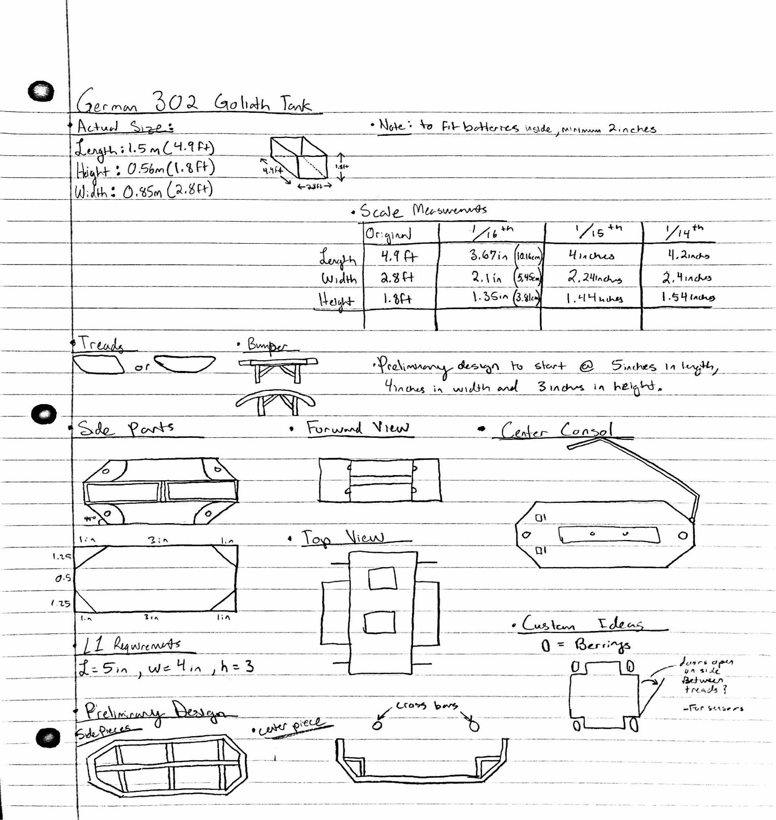
This is the beginning of creating a scale model of the German 302 goliath tank. Since it is the beginning of the semester and my team wasn’t set on the location of all of our electrical components inside the tank I wanted to create an open design to be able to fit any of the pieces they needed.

Details:

For this design I wanted to follow our professor’s request in having both motors in the back/front of the tank. For that reason I created the platform, but at the same time I didn’t want it to take up the entire back part of center console so I left a gap underneath for wires and other pieces that might need to go underneath. The opening at the bottom of the center console was to allow the line following sensors to function internally. As for the top and side pieces I wanted to keep them open to have options in terms of our placement of all of our components. Lastly, the side pieces were made thick enough to be able to screw into and attach to the bottom part of the tank. The design is meant to be simple yet sturdy to accommodate for the weight of the components being put into the tank.

Figure 1. Shows an explosive view of the first design I made to focus more on the overall shape of the tank and start sizing components that we could be using.

Conclusion:

It is better to have contacted all of your printing resources beforehand, for some reason this print took a while to get to me and I had to move on to the next design the next day. Overall, this design is much larger than what we want to get to, but it would serve as a good foundation and a start to what we have coming.

2nd Iteration: March 2nd, 2018

Introduction:

Following the German 302 goliath tank I leaned towards the previous model for my inspiration. At the same time I also wanted focus my efforts on designing an efficient and realistic side piece, for that reason I wanted to test different methods for the design.

Details:

With this design I decided to try and get close to the older model from a previous year. In this design I wanted to skip forward in creating a housing space for the motors and making a permanent space for them. On the same piece I also introduced the opening on the front of the bottom piece for the range finder.

I also started to design the Hinges for the side portion. I wanted to deviate from the old model and crate a moving support hinge so my first thought was to create half of the hinge beginning from the bottom of the side pieces. And the small circular parts in between the hinges are meant for the other end of the spring to connect to from the “bottom wheel hinge” photo.

As for the top portion I wanted to keep the inside accessible while mimicking the lids in the original German goliath 302 model. I wasn’t sure how much room they needed inside the tank so I kept it open in case of overflow.

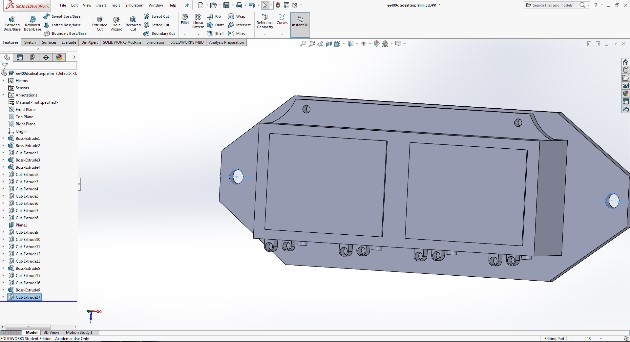
Figure 2. Is the image of the bottom hinge and its design. The total width of this piece is 5mmand should hold 2 wheels on the bottom edge

Figure 3. This is the side piece as a whole, the box is hollow and the four pairs of loops at the bottom resemble the placement of the hinges that will hold the wheels.

Conclusion:

After the print I realized there were some changes that needed to be made. One of which was the size and thickness of the wheels or the set up I had to hold them. I also noticed that the box is a little too big and too square so in the next coming days I’ll be thinking of a way to fix that. I haven’t been able to access the files of the previous models design through this class on the google drive so most, if not all, of the upcoming designs and modifications will be made from scratch.

3rd iteration: March 14th, 2018

Introduction:

Last week I got the bottom piece printed first through Ridwan and found a few mistakes only found through printing. While waiting for the other prints I decided to move onto the gear. I didn’t know how to make gears so I had to do a little research on my own and from that I created the design that’s shown in this folder.

Details:

In this iteration of my design there wasn’t that much to change but there were some key features that I needed to fix in the bottom portion of the center console. For example, the size of the opening for the range finder wasn’t exact so I wanted to fix that. The bars over the motors should be more secure over the motor compared to the last iteration. The last thing I did was adjust the length of the bottom I noticed that before it could only fit the 3dot board itself not considering any of the cables that could be running in front or behind. As you can see the gear resembles the ideal look of the one in the photo, but the tips of the gear ended up being too wide for the treads themselves.

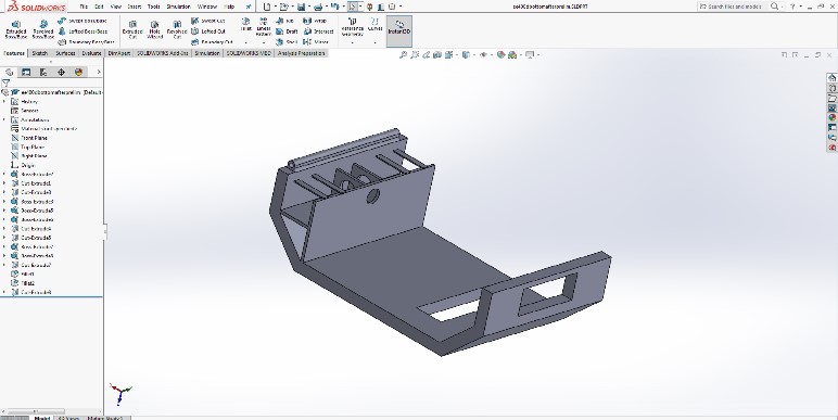
Figure 4. Is the first leap into designing the bottom piece of the German 302 goliath tank.

Figure 5. At some point I knew I was going to have to create a gear that mimics the Tamiya so to start of easy, this is the first design of the gear I’ve created, based off the Youtube training video I found and the image of a tank that Ridwan showed me.

Conclusion:

While waiting for the electrical components I need to check the dimensions of the pieces themselves to make sure it all fits together. For this iteration specifically I know I’ll be needing to change the dimensions of the gear because the spikes are too think for the treads we have.

4th Iteration: March 20th, 2018

Introduction:

Things are starting to pick up in terms of design and trying to get a print available for my team. I managed to connect with maker’s society and access their 3D printing farm so my hope for the upcoming weeks and until the end of the semester is to have an appropriate turn out rate for the 3D prints of the iterations.

Details:

For this iteration, my goal was to have something for the group to work on before the break. I would like to start with the separate hinge pieces, I decided to try a different design, something new, because the previous design didn’t work as well as I thought, the wheels that I would have had to make for the previous design would have been too thin and too small in terms of diameter due to wheel bite. As for the rest of the side, I modified the “ee400d4thsidepart[s]” to look exactly like the previous semester but still implementing the hinge concept in terms of separate pieces and separating the wheel placements above the piece. The spacing in between the top and bottom wheel placements are different which is why I have two different wheel sizes

Figure 6. This is the second attempt at making a hinge that could work underneath the main side piece.

Figure 7. The spacing in between the top and bottom wheel placements are different which is why I have two different wheel sizes.

For the center console, I would like to first point out the hole in the “ee400dmiddleconnector” piece. The reason why I put that gap there was to help create space for the components that we put inside the tank, which is why there is also a hole in the center side pieces as well. For “ee400d4thbotpart” the only difference I made was the opening at the back of the tank for the micro-USB cable to run through. Lastly, for the top I was told there was a possibility of using a UV sensor in our tank so I created an opening for the sensor to go through and I also tried to mimic the placement of the panel openings on the German 302 goliath tank found online and previous models.

Conclusion:

I hoping this design will work out in terms of the hinges and the opening on the sides of the tank to fit all of the electrical components. At this point in time, my group is still in the coding phase and building the PCB so I’m still not sure on what they are implementing and integrating into this design. My goal for the break was to create at least the center console for the rest of my group to figure out how to place the rest of the components inside the vehicle so that way when I got back from break I would have something ready for them.

5th Iteration: April 5th, 2018

Introduction:

Over spring break, even though I was out of town, I was able to get my Solidworks program on my computer to work and came up with a model ready to print by the time I got back. For this new design, I was advised by both Professor Hill and Ridwan to follow the images of “Monkeyfab’s” Goliath tank model. After doing a little bit of research, I had to size it down and change a few components to accommodate for our size restriction and location of our electrical components but at the same time followed the new design.

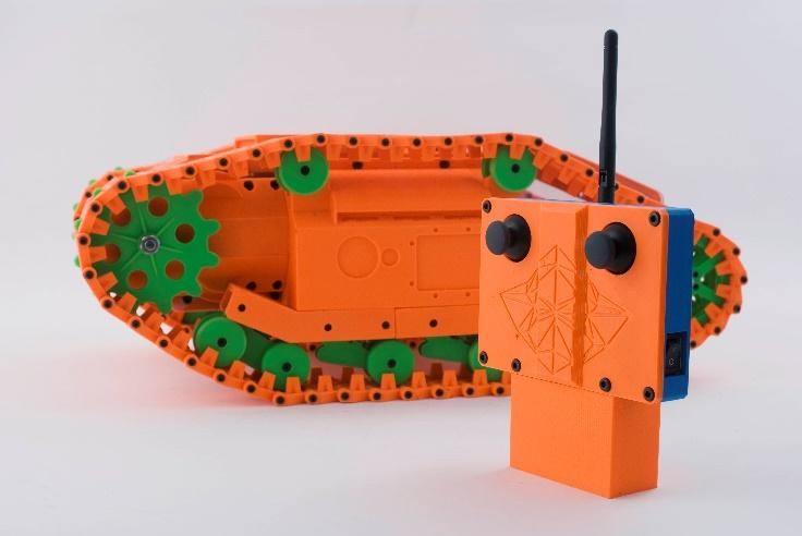
Figure 8. The Goliath tank was following inspiration from the MonkeyFab design.

Details/ Modifications:

Before spring break, I practiced on how to make gears so I did a little research on my own and from that I created the design that’s shown in this folder. The reason why I chose to follow the design of Tamiya’s gear is because I wasn’t sure if I would have enough time to create and print all of the pieces for the treads so I stuck with the gear that resembles the look of the parts provided in the kit from Professor Hill.

Figure 9. A copy of the Tamiya gear design with the adjust length of the spikes so that it catches the tracks better.

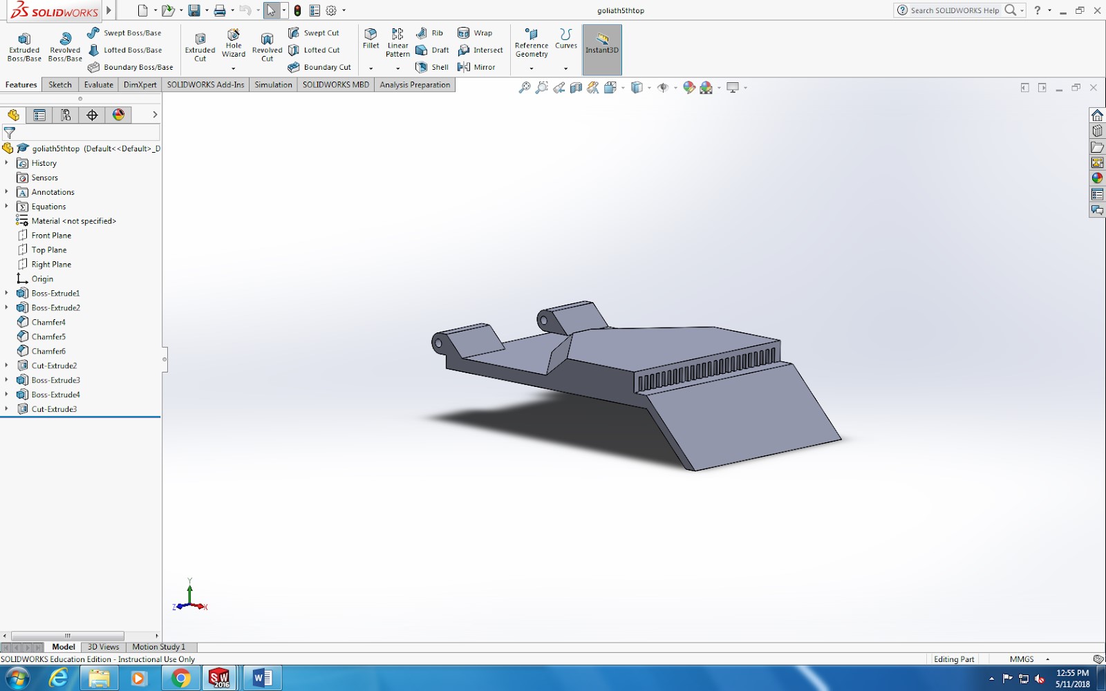
Figure 10. From that I moved onto the top piece and again I tried to mimic what I saw in the monkey fab photo and was able to recreate the look. I didn’t have too much space but I resized it to fit on our tank and look like the part.

From that, I moved onto the top piece and again I tried to mimic what I saw in the photo and was able to recreate the look. I didn’t have too much space but I resized it to fit on our tank and look like the part. As for the hinges, again space was a concern and I wanted to have a strong hinge so I put those parts on top of the piece extending outward which would connect to the bottom piece which was modified to accommodate for the new hinge.

Lastly, the “5thiterside piece” has an opening towards the back of the piece which lines up with the motor placement. The holes along the lower perimeter of the piece were my idea of finding a way to attach the side pieces without getting in the way of the closing hatch. One of the things that I had to think about was how to efficiently keep the lid closed on the tank.

Figure 11. This is a side view of the side piece used on the center console. The wholes along the bottom edge represent the pin locations to keep it closed.

Conclusion:

One of the things I realized while researching this new design was that there were no “stl” or “solidworks” files for any of the parts shown in the monkey fab design. I was able to find multiple images which gave really good insights on what the pieces look like, but none of them gave concrete dimensions on the size of their tank. Also their gear system is a lot different than ours which is why I don’t have an additional piece on the side of the tank behind the green gear in the picture above. Overall, there was not much to go off of but I did end up scaling the image above and was able to produce a center console close to what the tank looks like now.

6th Iteration: April 12th – 16th, 2018

Introduction:

After my first attempt in trying to design parts of this new model, I tried putting it all together and noticed a couple things wrong with the prints. I also put my focus on all the pieces that were going to be implemented to make up each side of our tank.

Details/Modifications:

Since last week, I’ve made some pretty big changes to our model. Starting off with the bottom of the tank I added two tabs on each side of the bottom piece that has a 3mm diameter hole to screw the corresponding holes on the “sidepiece041718” to create the center console. This will allow the side walls of the center console to have a better connection to the bottom piece and create a sturdy tank. The other difference I would like to point out on the same piece is that I moved the hinge from being on top of the tank to becoming a part of the top and making the hinge flush.

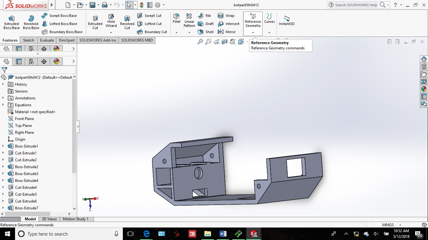
Figure 12. Here is the 1st iteration of the bottom piece from the new model.

When designing the new model, there seemed to be a lot of parts in the image provided to create the side piece. First off I created the hinge holders in two separate pieces to resemble the design. One is the front and the other the back, designed to each hold two hinges. These two hinges would then be screwed underneath “centersidepiece” along the outside edge to resemble the look. The “bsidehingeholder” is meant to fit completely underneath the center side piece with only the lower half of “fsidehingeholder”. The angled portion of “fsidehingeholder” is mean to hold the “motified bottom hinge041618”. The new wheel holders are meant to hold two thin wheels created earlier this semester on either side at 5mm in diameter and 2mm in thickness and on the end with the small tab.

Figure 13. This is the front end of the side hinge holders that will be screwed under the center side piece along the outside edge.

Figure 14. This is the center side piece that makes up the majority of the side of our tank. The circular and rectangular indentations represent the design of the tank used in the 1940’s.

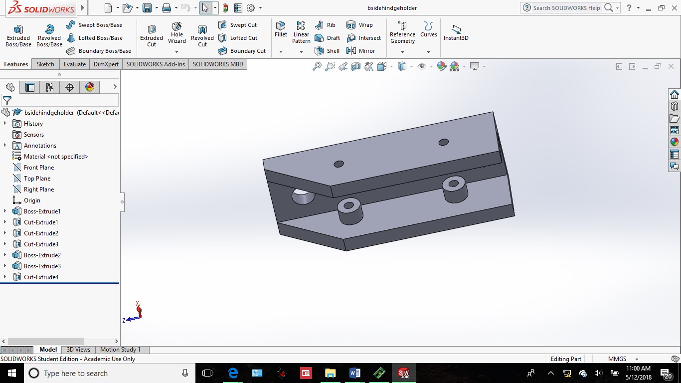
Figure 15. This is the back end of the side hinge holders that fits perfectly underneath the length of the center side piece along with the other hinge holder Figure 13.

As for the gear, I used what I learned from the first attempt to create this second-gen gear and try to follow the Tamiya design provided by Professor Hill. With this gear I also had to modify the size of each part. For example, the diameter for the motor to go through was a little more complex than just a circle so I created a shape that would catch onto the flat side of the motor bit and rotate as needed. The spikes were also altered in a way that would extend them out a little bit further to better catch onto the treads.

Figure 16. The circle in the center of the gear is not a perfect circle which is designed to catch the flat end on the motor pin.

Conclusion:

These new pieces should bring our team that much closer to completing the design. I hoping that when these pieces print that they all come out fine and work the way they should. One of the other things I have to think about in the upcoming week are the attachments/placements for the springs.

7th Iteration: April 18th, 2018

Introduction:

Last week I managed to create and print the majority of our parts for this design A few problems that I ran into this week was with the printing properties mainly the quality of the overall print. Even though the printer can print at 50 microns, there was one component in particular that I wasn’t aware of being too thin. Which lead to some changes that I made this week.

Details/ Modifications:

For this Iteration, there wasn’t that much of a difference from previous methods but the hinge on both the top and bottom pieces of the center console were too thin to maintain a solid hold on each other. After the print and while attempting to put it together the hinge started to break. Because of that, I designed the hinge to be thicker than the model before approximately 1mm all around compared to 0.5mm. I also wanted to point out that this was the first design in which I implemented a trade-off study, specifically the hatch closing feature which has two pieces that extend from the top and snaps closed on the corresponding grooves on the bottom piece.

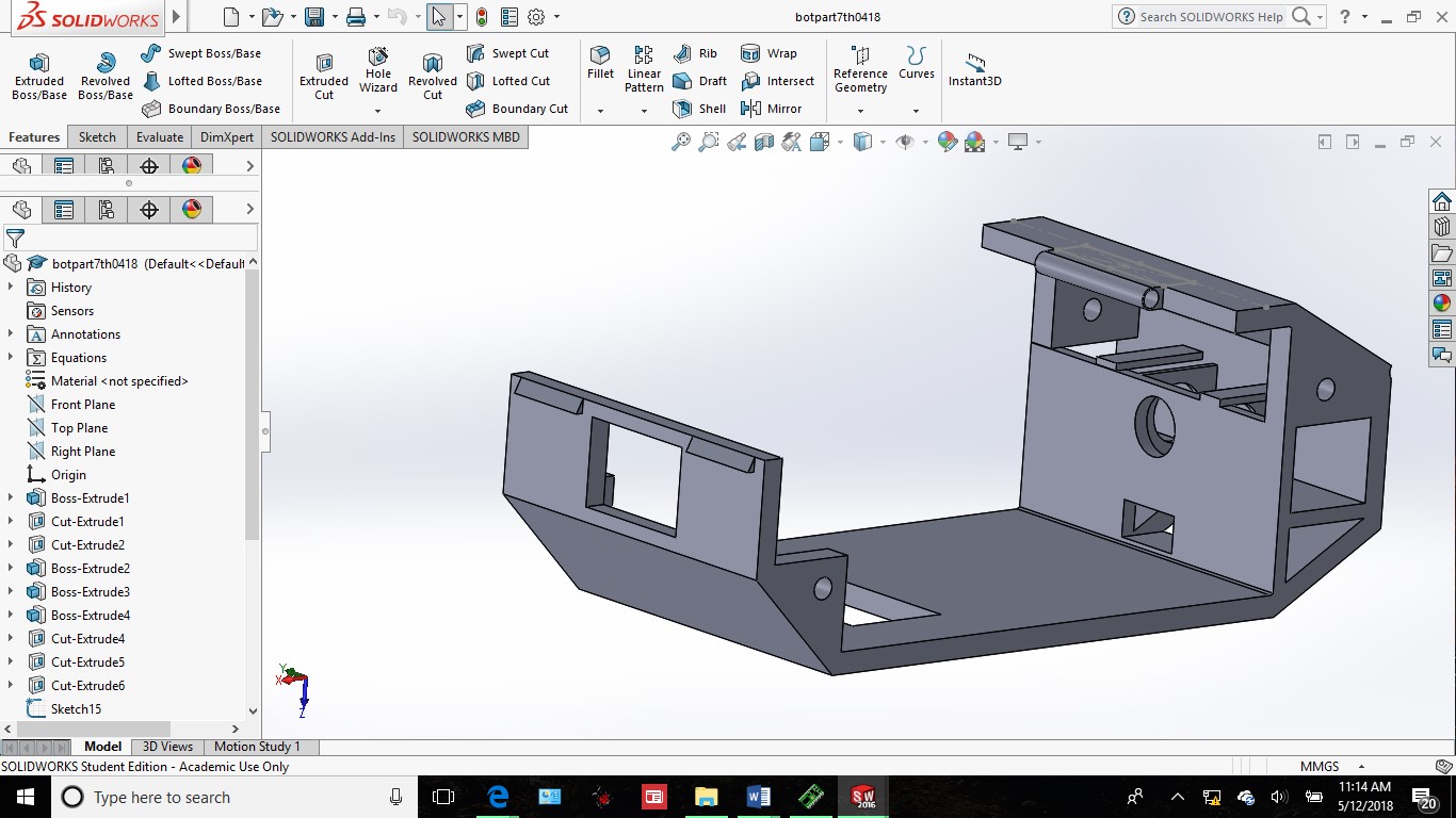
Figure 17. The tradeoff study being implemented on the front of the bottom of the tank shown with the two rectangular triangles on either side of the range finder opening.

Figure 18. The same study being implemented on the front of the top of the tank, but looking at it from the back.

Thanks to Ridwan’s casing for his caliper, I thought of an alternate way to close the lid. His storage case for his caliper has two snapping pieces the keep the box close, which in turn lead to the closing features I added to my design. The reason why I made two tabs was because I didn’t want the lid to get in the way of the range finder. Lastly, there still wasn’t any notifications on the orientation or placement of the 3dot board which is why I don’t have a set or fixed location for the electrical components.

8th Iteration: April 19th, 2018

Introduction:

After making the modifications last week I found that there was still some more work to do. This week I focused on modifying the tank to some of the components we had just bought from McMaster-Carr and Sparkfun.

Details/ Modifications:

For today’s rendition of the bottom piece, I changed the size of the opening for the range finder in the front.  For the bottom hinge folder towards the back, I added two points for which the springs from McMaster will connect. For the other hinge, I did the same, but I also extended the length of it to accommodate for the minimum size provided by McMaster-Carr.

Figure 19. Identifying the small tabs along the length of the back side hinge holder two rectangles placed.

Figure 20. Due to the length of the springs from McMaster –Carr I needed to adjust the placement of the tabs on the front side hinge holder as well.

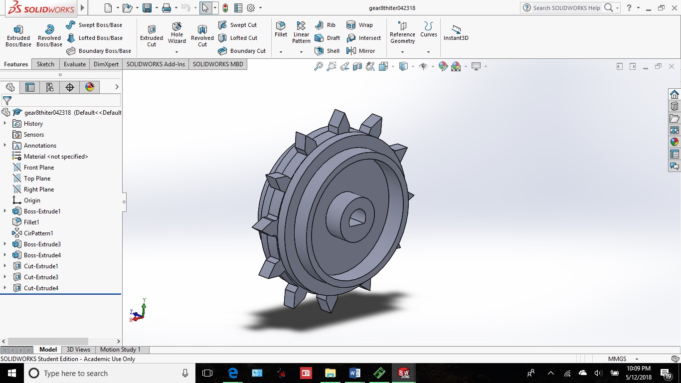
Figure 21. Changed the length of the gear spikes to a finer point and subtracted 0.5mm.

I noticed after the last print I made that the spikes on the gear held onto the treads too long while rotating. To fix this problem I changed the length of the spikes but tall enough to efficiently run the tank. I also changed the diameter of the placement for the motor pin. Previously, I took an exact measurement on the motor pin and matched that on my gear but I found that, due to melting properties I had to make the hole a little bit bigger.

Conclusion:

I’ve realized that when using multiple printers as your source of production, it is hard to determine the right size for every piece every print. Every printer has a different effect on the material we used to print.  I’ve noticed that so far I’ve used four different printers between Ridwan and the 3D printing farm at maker’s society.

9th Iteration: April 23rd to 25th, 2018

Introduction:

It’s getting towards the end of the semester, luckily, this week I got some details on the dimensions of the electrical components that we’ll be using inside of our tank. So my focus for this week after talking to Professor Hill is to get an idea of how I’m going to mount the electrical components to the chassis.

Details/ Modifications:

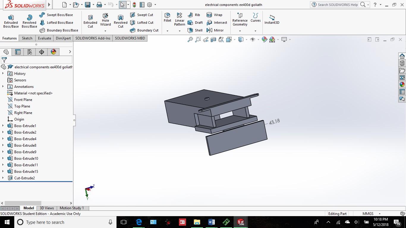
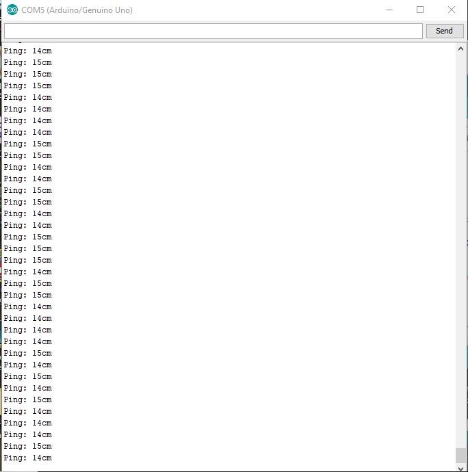
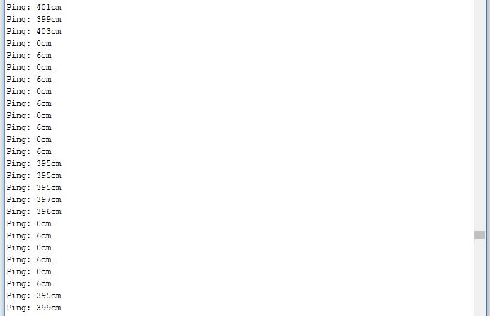
Figure 22. Top view of all of the electrical components. And the 43.18 represents the length of the proposed PCB.

Figure 23. This is the bottom side of all the proposed electrical components connected to each other.

Today on the 23rd I was told about the electrical components and their exact dimensions. The biggest piece of the electrical components resembles the 3dot board, provided by Chris H. at 3cm x 7cm. The next larger, thicker rectangle resembles the size of the battery that would be on the board. Next, are the two female pins that are holding the PCB over the 3dot board and the range finder that is connected to the PCB. Concept option suggested by Professor Hill.


Figure 24. The holes at the bottom of the center side piece serve as a guide to the placement of the screws to combine the hinge holders to the center side piece.

For the center side piece, I had to adjust the placement of the screws and hinges which then lead to re-printing the rest of the side pieces. Before the screw points were centered onto the piece, with this new layout I moved them more to the flat end, rather than the cut off end, to extend the length of the hinges and to allow more space for the moving parts as seen in the picture of the original design. I also changed the width of the material surrounding the holes on the previous design to 1mm as shown on “wheelholder9thiteration”.

Figure 25. Had to adjust the width of 3D printing material that surrounded the holes so that way it didn’t print weak and breakable hinges.

As for the center console, I added a screw point just to test and see where I could line up the 3dot board in reference to the top (a piece that will be removed/ modified later when I get the exact dimensions and the physical parts). Lastly, there was a small change on the side piece in which I added a 3mm diameter hole for the other tank wheels to go through.

Figure 26. Wanted to show the addition of an extra hole to serve as a guide to the rolling wheels opposite of the gears.

Conclusion:

As we move towards actually demoing and implementing our electrical components I noticed that there is about a 2cm gap between the placement of the electrical components and the bottom of the tank. Further iterations at this point depend on how the prints come out and whether or not the group and or instructors see any changes that could be made.

10th Iteration: April 26th –April 30th, 2018

Introduction:

As it’s getting close to the end of the semester, I’m looking to finely tune specific parts to get our tank looking like an actual model. Over the past week, I was able to create a secure position for the 3dot board and my hope is to have a physical 3dot board ready for the next print.

Details/ Modifications:

As our tank is getting closer to our final design, I had to play around with the length of the hinge holders to make sure I had space for everything. For example, the small tabs that lead to the springs on “10thiterbsidehingeholder0430” moved closer to the hinge to avoid being broken off. To make sure the width between the wheels matches the width of the guides on the tread I modified one of the older designs to change the thickness of the wheel to 2mm.

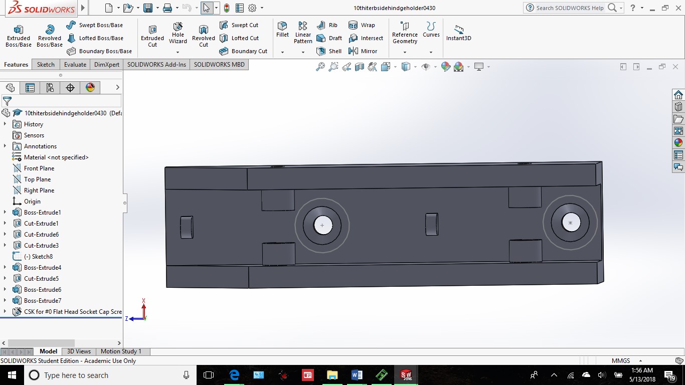
Figure 27. After the print I realized I had change the placement of everything a little bit by making more space for the springs.

One of the key new features that I added to my tank is the mounting points for the 3dot board on the “goliath10thtopwhinge” piece.

Figure 28. The electronic components file is the same as before but this time I added two points on the front end of the lid to screw the pieces on and the two groves in the back used as guide and placement of the back end of the electrical components and securing it to the lid.

In terms of the bottom piece, I had to change the placement of range finder viewpoint to work with the modification of the top piece and location of the electrical components. I also moved the location of the line following sensor opening closer to the front to line up with the electrical components on the lid.

Conclusion:

After the prints were made, the plain 3dot board used in previous semesters given to me to test and see if the board fit. Due to false information, the width of the board was actually larger than I was previously told. Along with other parts, I’ll be making some more modifications and prints in the next couple of days.


11th Iteration: May 3rd, 2018

Introduction:

After making a few modifications earlier this week I was able to quickly get the prints from Maker’s Society, but some of the parts I made didn’t really seem to fit the way I wanted it to be. For example, the dual hinge had a while biting problem so I played around with different lengths. The spacing of everything underneath the center side piece needed an adjustment as well.

Details/ Modifications:

Starting off with the dual hinge, had to adjust the overall length of the piece because it was too close to the hinge holder and gear. My solution was to extend the piece above the two-wheel pin locations by 5mm (12.5mm total) then realized that it was too long so I decided to take off 3mm and changed the length again to 9.5mm.

The next couple of parts I would like to talk about are the front and back side hinge holders. In all of the previous designs, I was concerned about the spacing for the hinges and screws. In this design, I feel like I have figured it out in the sense that I put three of the tabs for the springs on the “11thiterbsidehingeholder” moved the screws and adjusted the spacing on “fsidehingeholder11th”.

Figure 29. This is the back side hinge holder that extends past the length of the bottom edge of the center side piece.

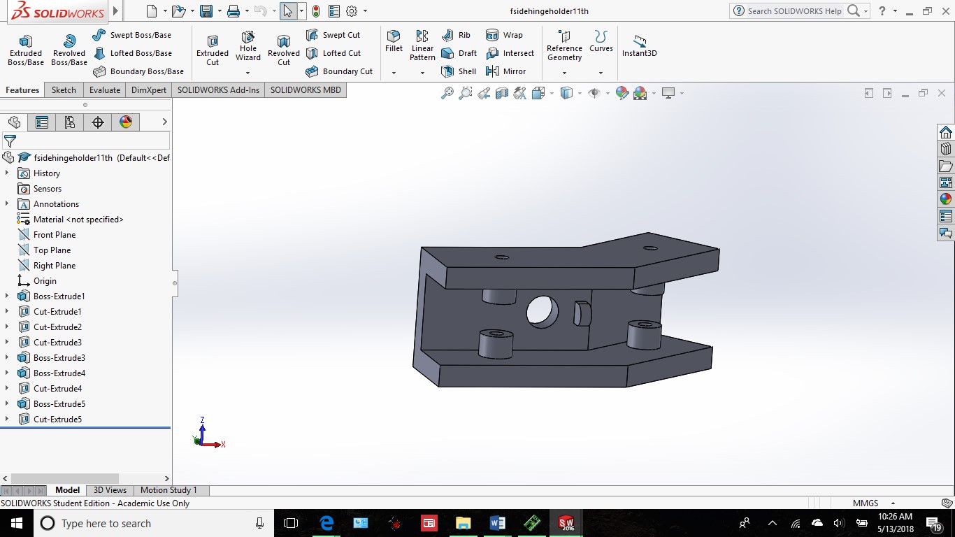
Figure 30. This is the front side hinge holder which will be angling towards the gear.

For the center side pieces, I also realized based off my Solidworks knowledge capabilities that I can’t mirror sketches and the hole locations on an entire piece. For that reason, I created two center side pieces in order to solve that problem. On this same piece, I coordinated the new screw locations on the side hinge holders to the bottom of this piece.

Figure 31. The adjustment made to creating space for the 3dot board mounted to the top of the center console.

The “goliath11thtopwhinge” piece has only one small difference, I increased the gap of the 3dot board holder by 2mm to adjust to the actual dimensions of 3.5cm in width. It is now 33mm in width from the part’s base. The reason why I made the gap 2mm smaller than the actual size was that I wanted a tight fit and I had the width of the top piece as a size constraint if the parts were any smaller they could break off easily. I also adjusted the length of the top piece by 0.5 mm to make it easier to open the lid of the center console. I also created the rolling wheels that would be opposite of the gears on the tank. I also included the screw points of the center side piece to the “sidepiece11th”.

Figure 32. The four hole in the center off the side piece represent the locations of all the screws that will hold the center side piece up.

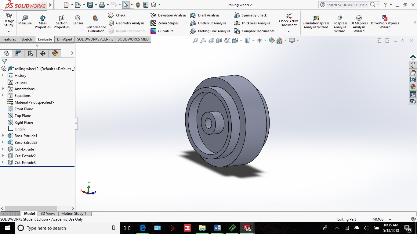
Figure 33. This is the 3D rendition of the wheels used on the opposite side of the gears.

Conclusion:

Although I have all the parts printed, I’m not too stoked that there are different colors in the design. If there is enough time, I’ll be looking to make everything the same color. Between the size constraint of the springs from McMaster-Carr and the size constraint of the tank, the center console sits a little too high above the ground compared to what I wanted. In this upcoming week after the remaining prints, I’ll be looking for any last minute modifications that need to be made.

12th Iteration May 10th, 2018

Introduction:

This is crunch time, it’s cutting it close but there some very important changes that needed to be made. For this last iteration of my design, I edited quite a few pieces. Pieces in which I’ll discuss in this blog post.

Details on Modifications:

First off, there were a couple of things that didn’t need changing, but a reprint. For example, the “11thiterbsidehingeholder” and “fsidehingeholder11th” is correct in terms of dimensions and design but for some reason, the piece was warped and wasn’t flushed with the outside edge of the center side pieces. Also, the gear and wheel holders were printed in a different color (pink) so I asked for a re-print to match the color scheme.

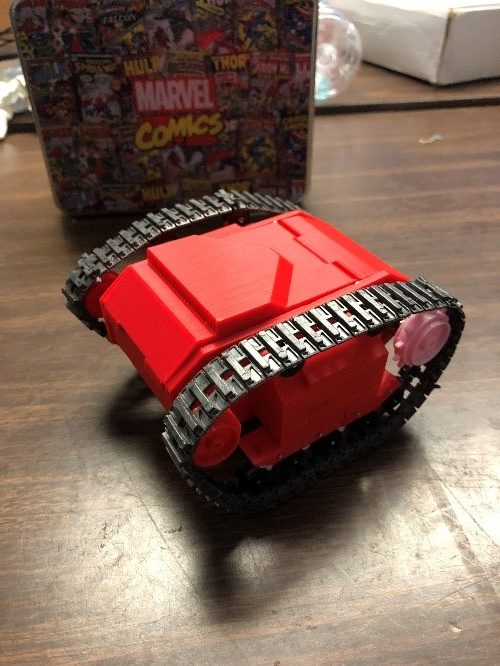
Figure 34. Top view of the 11th iteration of our tank.

Figure 35. Side view image of the tank, it’s kind of hard to notice, but the tank rides pretty high off the ground.

For the center side pieces, the orientation of the squares and circles on the outside face were backwards so I fixed that to match the model below. As for the dual hinge, the arm was still too long so I adjusted the length to allow the wheels to fall just below the “fsidehingeholder11th”

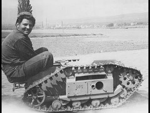
Figure 36. A photo of an actual German 303 goliath tank from WW2 in 1942. Also known as the “doddle bug” by the soldiers at that time.

Moving on to the center console. The orientation of the front of the tank and the gears is going to be a bit backward, but it should still work all the same. In the previous iteration I had the gear and the “rolling wheels” leveled with each other, but that doesn’t match the 303 goliath model it looks more like the 302. For that reason, I extended the face with the range finder port to about 27mm rather than 20mm and I made the tabs towards the front of the bottom piece a bit larger to accommodate for both the screws to go through above the hole for the bushings and bring the axle lower to get that 303 look. For the top piece, I followed Professor Hill’s request in making only one tab to snap the center console closed. The only reason why I had two before was to make sure the range finder can “see” between the two tabs.

Lastly, for the flat side pieces, I relocated the corresponding holes to the bottom piece of the tank and created a housing to cover the exposed motor piece on either side. I also adjust the lengths of all the edges to match the perimeter of the center console.

Conclusion:

For the number of iterations that I went through, this project really enhanced my solid works skills and my ability to adapt quickly to changes. For example, after making these last modifications I realized I received some poor quality prints but was able to redesign them fast enough to get a new printed model. For the next semester, my recommendation would be to try and find a good way to fit both the range finder and the motors on the same side. I’m hoping that with my submission my files can be accessibly viewed by others to take the next step forward.

References

  1. http://www.monkeyfab.com/goliat_sterowanie/
  2. Figure 36 was from a youtube video
  3. https://www.solidworks.com/


Goliath Spring 2018 – Turning Method

By: Tai Nguyen (E&C Engineer)

Verified By: Ernie Trujillo (Project Manager)

Approved By: Miguel Garcia (Quality Assurance)

Table of Contents

Introduction

The turning method of choice was turning using a gyro.  The gyro we chose was the SparkFun Triple-Axis Digital-Output Gyro Breakout – ITG-3200.  This specific breakout features an I2C serial interface, optional external clock, and digital outputs for X, Y, and Z axis angular rate sensors.  The VDD supply voltage ranges from 2.1-3.6V.  We ran tests using a 3.3V VDD from the SparkFun ProMicro 3.3V 8MHz.

How does a Gyro Work?

Before getting started, it is important to know how a gyro functions and how to use it.  A gyro measures angular velocity, the rate of change of the angular position over time, which is usually given in degrees per second on the datasheet.  If you want your robot to turn a certain amount of degrees, for example, a 90-degree angle, we would not need the angular velocity, but angular position.  From Calculus I, we know that the derivative of position is velocity.  To obtain a position from velocity, we will need to perform an integration.

An integration involves your variable multiplied by some delta time.  Most people know of integration as an “area under the curve” and to solve for more parabolic curves, techniques like left-side, right-side, midpoint, or trapezoidal integration come to mind, where it is a sum of multiple areas across a delta time.  In digital systems, it is very difficult to perform continuous integration, so the simpler solution is to take a sum of finite delta angles over delta t.

Figure 1: Trapezoid Integration


Initialization code

Figure 2: Initialization code

These are global variables created outside of void setup() and void loop().  The first variable is a float data type to achieve the best accuracy when it comes to integrating (the closer we can get to 90 degrees ex: 90.039 degrees, the better).  We also want a static variable qualifier to preserve the angle data as we slowly add each delta angle loop after loop.  The variable then is what is going to keep track of how much time has passed since call of the millis() function, which stores time passed in milliseconds.  tSpeed is a constant to determine our turn speed for our motors.  zRate is a SIGNED 16-bit variable that records the angular velocity.

Main Code

Figure 3: Error correction by use of if statements

A common issue with any gyro that must be fixed is drift.  When your gyro is sitting still, there is an offset or an error that occurs.  Try plugging in your gyro and reading the angular velocity while it is sitting still.  That is your error for that axis.  Over time, this angle offset will add up to multiple turns/rotations and that is what drift is.  There are 2 ways you can try and solve this issue.  One way is to first notice that your error tends to jump around, like for example, you’re reading the zRate and it’s displaying 5.25, 5.06, 5.78, 5.60, 5.80 and etc.  The error is not a constant.  So the method to get a singular constant error would be to run a 20 point average.  A running average takes N points of data and finds an average.  To do this, you would apply a for loop.

Figure 4: Example 20-point average code

Here is an example that sums up each point of data using a for loop.  After you find the sum, create a new variable and divide that sum by N amount of points that you recorded.

Figure 5: Calculation of average

After you get this term, when you record your zRate, subtract this offset value and you’ll achieve a near 0 value when you’re not moving.

The second way of calibrating your velocity offset is to apply a hysteresis (double threshold) with if statements.  Figure 2 shows if statements that say, if the speed is less than +2 and greater than -2, then the gyro is not moving and to set the angular velocity data = 0 degrees/second for that reading.

Figure 6: Integration code

Uncomment the Serial.println(currentAngle) to test and track how many degrees your gyro has rotated.

Below is the turning code for right turns and turning around:

Figure 7: Gyro code for Right turn

Figure 8: Gyro code for turning around

Conclusion

Gyros are great tools that have applications such as orientation measuring or turning.  A gyro outputs an angular velocity which we use to determine angular position through integration.  In almost every gyro, there is an error that accumulates over time called drift.  Drift occurs when the gyro rotates faster than you can sample and so your integration approximation is going to be incorrect.  Integration in digital systems are never 100% accurate so there will always be some small error in the end.

References

  1. https://www.sparkfun.com/products/11977
  2. http://tutorial.math.lamar.edu/Classes/CalcII/ApproximatingDefIntegrals_files/image002.gif