Height Requirement

By Maxwell Nguyen

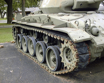
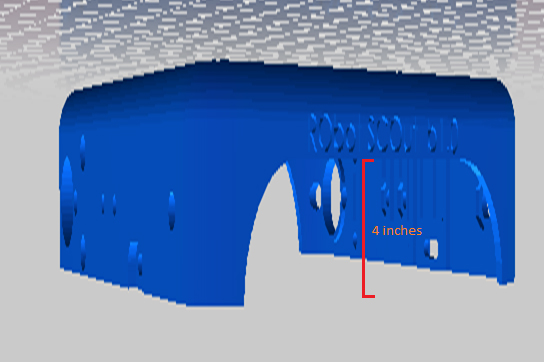
Along the designated course shared by the Rover, Spiderbot, and Hexapod, the most notable obstacle was a sprinkler head with the height of four inches.  The orginal Arxterra RoSco is design to travel primarily through flat surfaces and is not equipped to move over obstacles at such height.  In order to clear this four-inch sprinkler, the rover team will be examining a design solution that will allow the new rover to achieve the height requirement.

The rover team has agreed that extending the height of the rover is the most simple and efficient design solution in order to fulfill the height requirement.  By taking the original chassis (or body) of the rover and extending both sides we will be able to give the rover a height clearance of 4 inches.

body

In order to extend the sides, several methods will be weighed against each other.  One approach will be to have the manufacturing division remodel the chassis of the rover to fit our needs.  However, due to time constraints and inefficiency from remodeling the chassis we will opt for a difference solution.

The most efficient solution the rover team decided upon is to mount two wooden height extensions, one to each side of the rover.  This will eliminate the need for plastic remodeling and simplify our design solution.  Similar holes drilled into the bottom of the wooden extensions will allow us to mount the motors, wheels, and track at the bottom of the extensions.  This will thus give the rover a significant height increase.

Opto-isolator

 By Chau To

Optoisolator is a component that transfers the signal between 2 isolated circuits. It consists of an LED and a phototransistor as shown in (Figure 1). When a signal is applied at anode (cathode is usually connected to ground), the LED will emit light that shines on the base of the phototransistor turning the transistor on. The optoisolator is used to isolate two parts of a circuit that has different power consumption such as between a micro controller and the DC motor.

Why Optoisolator?

Since the hexapod drives servos directly from the digital pins of the Arduino board, the Optoisolator will provide protection for the board by isolating the servo and Arduino. Since the servo consumes a large amount of current than the board, a power surge could happen and as a result the current from the servo could damage the Arduino. In addition, servo is a very noisy component; the noise could leak to the sensitive microprocessor.

How to connect?

figure 2

As demonstrated from the figure, the output from the PWM digital I/O pins of the Arduino connects the anode than the cathode is connected to ground. The Servo has 3 pins (or 3 wires). The Vdd wire connects to collector of the phototransistor; the other 2 wires connect like figure 2.

Operation: When the PWM is high, the LED lights up; the transistor will switch on. The servo control pin is high, and the servo shaft will rotate.

How to choose an optoisolator?

There are many types of optoisolator in the market. The two important parameters while choosing an optoisolator are the diode forward current and the switching time. The maximum forward current can be found in the data sheet; for the Ardunio the maximum rating forward current should be around 50 to 80mA. The switching time of the optoisolator determines how fast the phototransistor turn on, or what the delay is when the signal passes through the isolator. Nowadays, optoisolator has very fast switching time in micro-seconds.

The hexapod team will use a PS2501-4 Optoisolator 4-channel (4 Optoisolator in 1 IC) to operate the robot.

 Datasheet can be found at: https://www.sparkfun.com/products/784.

figure 3


Track Research

By Maxwell Nguyen, Project Manager

 The rover team is researching new ideas for treads/tracks for the rover.  The current tread belt is one continuous belt that takes hours to print.  In addition, one small mistake could potential ruin the entire track and make it completely useless.  In order to fix this problem, we will be looking into a new design that allows the belt to be split up into separate pieces.

Upon further research, we concluded that it was best to create our tread belt to resemble tank treads.  Tank treads are effective and can be produced as individual pieces before linking them into one continuous belt.  This will allow for faster track production and reduce the margin for error on the manufacturing end.

When searching for tank track models on Thingiverse (an open source community for 3D models and printing), we narrowed down three different types of tracks.  They can be viewed in the links below:

http://www.thingiverse.com/thing:163489

http://www.thingiverse.com/thing:163486

http://www.thingiverse.com/thing:199713

We will be working closely with the manufacturing division to develop a set a tracks and a new wheel to fit that will meet our rover’s needs.

Hexapod Final Model

By Mason Nguyen, Solid Works model by Vinh Kim

After many working hours, Vinh has finally created the real world final 3D hexapod model including the mounted with the cellphone. The hexapod will operate using 19 servos, 18 servos will serve as the hexapod movement while 1 servo will mount at the front to hold the cell phone. Vinh also modified few parts such as extending the femur length in order for the hexapod to travel over objects easier. We are on our final phase of this model and currently making pieces out of resin. Silicon molding will take place after the pieces are finished.

figure 1
Figure 1: Cell phone holder

figure 2
Figure2: Front Servo mount 

figure 3
Figure 3: Cellphone Samsung Galaxy S2

figure 4
Figure 4: Hexapod Final Model (Front) 

figure 5
Figure 5: Hexapod Final Model (Back)

Design – First Iteration

By Simon Abatay, 3D Modeling and Manufacturing

After a review with the Robot Company’s President, the initial tibia design was deemed unsatisfactory due to its flat nature. In order to tackle this, I decided to modify my original design to give it a more 3-dimensional appearance. My intentions with this modification step were to maintain some semblance of its original shape, while providing it with a newfound presence of solidity.

Blog6_image1

The picture above shows that there is a defined depth in all 3 axes of the tibia. This satisfies the 3-dimentional objective.  The tibia still retains its 7 inch height and has a shape similar to the initial design to satisfy the height requirement. In order to save weight, the inside of the tibia will be slightly hollow. The overall design will be constructed with enough material to retain the structural integrity of the tibia despite its hollowness. Below is an image of multiple views of my tibia design:

Blog6_image2

To test the quality of the design, I put it through a proper stress simulation in Solidworks©.

Blog6_image3

The green arrows in the image above show where the tibia will garner most of its support. The purple arrows represent where the external forces are being applied to the design. I chose to apply force in every possible direction against the bottom of the tibia. This was done in order to simulate the idea of the spider walking, since that motion is the time when tibia undergoes stress in all directions. The spectrum to the right of the picture shows the level of stress each section is undergoing. The stronger the section the more blue it is, and the weaker the section, the more orange and red. This simulation shows that when the tibia undergoes 50 Newtons of force in each direction, it can retain its shape with minimal deformation. This simulation shows that the tibia’s structure is sound.


Mission Objective Modified

By Kristine Abatay, Project Manager

Following the group’s preliminary design review presentation, we met with the Robot Company’s President and modified our mission objective. Our new mission objective is:

Complete a hexapod robot project whose creation will achieve a speed that matches the current Robot Company rover project, operate safely, be capable of maneuvering a predetermined route in a forest-like setting, and have a body comprised of three-dimensional components.

Trickling down from this objective allowed us to create a fifth project requirement:

5. The legs and chassis components of Spiderbot will be designed to have three dimensions.

The other project requirements can be found ina previous post where the project was introduced:

 https://www.arxterra.com/spiderbot-life-times-vol-2/

Additionally, the following tests have been created to verify the project requirements that have been written (they are listed in the order from which they have been introduced):

Verification Tests:

Test 1
If project Spiderbot is completed by May 12, 2014, then this requirement will have been achieved.

Test 2
In order to verify the speed requirement, a flat surface, straight-lined course will be measured out and Spiderbot will complete the course while being timed. The resulting quotient of the length of the course, with the amount of time it will take Spiderbot to complete the course, will be calculated. If this value is equal to or less than the calculated rover speed, then requirement will have been achieved.

Test 3
The CSULB College of Engineering Health and Safety Policy states that “Faculty…shall: Implement the university’s Health and Safety Policy and all other university safety programs in work areas under their supervision/control.”

If Professor Hill, a faculty member of the CSULB College of Engineering, approves the operation of Spiderbot in the classroom, then this requirement will have been met.

Test 4
Verification of the height requirement will be done by measuring the height clearance, as well as the length of one leg sweep of the fully constructed Spiderbot.

Test 5
The requirement of a three dimensional design will be verified within the SolidWorks program, which enables our manufacturer to define the three axes of a design. If, at any rotated view of a component design, three separate pieces of the design can be chosen to define a respective x-, y-, and z- plane, then this requirement will have been fulfilled.

Speed Calculations & Component Modification

By Matthew Clegg, Computer and Control Systems

In order to tackle the initial calculated speed requirement of the rover project, we would need a starting point for Spiderbot. For this reason, I decided to make a calculation to determine the speed that the servo motors on Spiderbot’s legs would need to move in order for the entire robot to match the rover speed.

To try to estimate a possible speed for Spiderbot, I first calculated a velocity based on the speed of the servo motors. A servo’s rated speed is how fast, in seconds, the arm can move 60 degrees. To apply this to Spiderbot, I took into account the motion of the bot in a tripod gait, which is the most efficient walking pattern.

Assuming the length of the femur to be 5” (the value assigned to the initial Spiderbot design done by Simon Abatay in manufacturing) and the femur moving forward at a 60 degree angle (the speed rating provided by servo motor specification sheets), then using trigonometry,

eqn1 

In SI units, each sweep of the leg will cover 0.109 meters. In the tripod gait, the leg will move up 30 degrees, forward 60 degrees, then back down 30. Knowing the sweep of the leg is 0.109meters, he came up with a formula to find the time in seconds

eqn2

Dividing this time by 2 to account for both motions of the gait results in

 eqn3

The total degree movement of a leg is 30, 60 and 30 degrees. He divided 0.26s by two to find out how fast the servo moves 60 degrees to reach a speed of

 eqn4 

These calculated values are our project’s starting point. They are subject to change once more progress is developed with the rover project and more concrete details are obtained.

Lastly, it has come to our attention that using both the Mega ADK microcontroller and Adafruit breakout boards (as stated in a previous blog post for this project) would be redundant. The Mega ADK was considered because it could accommodate the amount of servos we would need to construct Spiderbot. Breakout boards were considered because it was the route that both spider projects took last semester in terms of design. We decided to instead use the breakout boards along with an Arduino Uno R3 microcontroller since we already have one in our possession, so the decision was mostly based out of convenience. Using these two components together will essentially be the same as using a single Mega ADK. An image of our newly chosen component can be seen below:

Blog4_image1 (1)
 (Image found at: http://arduino.cc/en/Main/arduinoBoardUno)


Spiderbot: Initial Design

By Simon Abatay, 3D Modeling and Manufacturing

Picking up from last semester’s Spiderbot project, the design for this project will have 6 legs. Though the name ‘spider’ implies 8 legs, translating it to a project would become very pricy in the long run since it would require more materials and power to construct.

Despite the difference in leg amount, we still wanted the design to be similar to an actual spider. The image below is of an actual spider leg. From this, we can see that spiders have 7 joints.

Blog3_image2

(Image from: http://havoc20.wordpress.com/2010/11/13/spider-tibia-structure/)

This would translate to seven servo motors per leg, and at 6 legs that would mean 42 servo motors! To save money on the final design, we’ve reduced our spider leg design to the 3 main parts: the coxa, femur, and tibia. This is the case with most hexapod designs that can be found online.

Three joints with a single motion each will mean each leg will have three degrees of freedom. This reduction will provide smooth movement for Spiderbot while walking and enough support for the spider to stand when stationary.

Keeping the reduction of joints in mind, the following image is my initial design of the spider’s tibia, which was created in the program SolidWorks.

Blog3_image3
One of the main issues with last semester’s design was maintaining balance while stationary. To avoid this, each tibia portion will have a tibia “plate” on opposite sides of the servo motor. To keep the whole tibia portion from collapsing on itself, each pair of tibia plates will be supported by metal spacers or standoffs.

The tibia will measure 7 inches in height as a response to the project requirement of clearing an obstacle of 4 inches tall, located in the planned route for Spiderbot.

For the body portion of Spiderbot, I plan to use a circle-based design since its shape will alow for uniform weight distribution. This way, the tibias will be evenly spaced out and, assuming the hardware will be placed in the middle of it, the center of gravity will remain at the middle of the Spiderbot.

Blog3_image4

The image below shows the design of the base plate. The radius of the center portion is 3 inches to accommodate the power source, the microcontroller, the servo breakout boards, and the Android© based cellular phone.

Blog3_image5

The extensions of the circle have a radius of 4.4 inches to accommodate the servos and their proper positioning (see rectangular cutouts).  The rest of the cutouts are for weight saving and heat ventilation. Seeing as a solid plate would have unwanted and unnecessary weight, it would be best to make cut-outs of the plate while at the same time leaving enough mass and surface area for the other components.

Wheel Consideration

by Robert Licari and Anthony Vo

We can take the wheels into consideration for the purpose of finding our desired velocity based upon our calculations.

If our Wheel Diameter (D) is 45 mm, then we can conclude the Radius (R) is as follows:
R= D/2 = 0.0225 m

Now we require a velocity equation that relates velocity to our wheel. For this task, we can employ a basic velocity equation with relation to angular velocity:

V = (R*w)/sin(theta)

Where “w” is angular velocity and our conversion from RPM to rad/s is as follows:

1 RPM = (2*pi )/60 rad/s

The spec that we have four our free-run RPM is 85 RPM @ 6V, which we shall use to find our normal velocity. In tandem with this, our application of the wheel requires that the angle “theta” be 90 degrees, or perpendicular, to our rotational axis, which effectively gives us:

V = 0.0225m * [ 85 RPM * (2*pi/60 rad/s) ]
 =~ 0.2003 m/s

 This equation can be applied to varying Diameter, but, for our purposes, we will use the 45 mm wheel.

 Level 1 Requirement:
— Speed according to the wheel diameter —

 The velocity requirement is defined base on matching the velocity of the standard ROSCO.  To calculate the velocity of the ROSCO, the circumference of the wheels and RPM of the motors is taken into account.  Given the wheel diameter, the circumference of the wheel can be calculated.  After scaling the measurements to meters and seconds, the rover is expected to have a velocity of at least 0.200277 m/s or ~0.2003 m/s.

Power Consumption Theory

by Robert Licari and Anthony Vo

Before we begin it is imperative to note that the power consumption equations calculated are heavily related to the amount of torque required to move the motors from rest to forward motion. In accordance with that idea, the following theory is calculated considering the worst power conservation possible. By that, we mean that there is probably no way that the Rover will draw this much power, but the fact of the matter remains that the equations are scenarios that can, and probably will happen. Our theory at this point considers that these scenarios are happening constantly.

 Having said that, we can do some simple addition in order to compare our power consumption:

 Power_DCMotor + Power_Servos = Motor Power Consumption

 5 W + 3 W = 8 W

 Now if we do a simple calculation involving the current, we can find the total current drop that the Rover will consume:

 8 W = 8.4 V * I_total

 I_total = 0.9524 A

 If our battery output is 800 mAh, then we can easily state:

 Operational Time = 0.8 Ah / 0.9524 A = 0.84 h

 0.84 h ~ 50 mins

Given our simple calculations and considering only the power consumption of the motors itself operating constantly at their rated voltages, we should be able to run the motor for approximately 50 mins.

Bear in mind that this is an ideal situation and is not considering physical constraints and is assuming constant heavily-powered motion from our motors. The reason the calculations were done this way is to illustrate a time that was within our overall assumptions as well as a starting point for the next phase of calculations being the physical constraints of our payload (the rover itself) as well as additional power concerns involving the microcontroller.