By 3DoT David team:
Omar Mouline (Project Manager)
Christopher Hirunthanakorn (Missions, Systems and Test Engineer)
Kent Hayes (Electronics and Control Engineer)
Andrew Saprid (Manufacturing and Design Engineer)
Executive sumary
One of the 3Dot David project objectives was to build a small-sized spider bot that can walk using two motors. When the project was assigned to us, we did research on different movement mechanisms in order to choose the one that best suits our requirements. The research results can be found on this blog post: Spider Bot Different Mechanism Research
Project Objectives
The objective of 3DOT David Spider is to use scaled model of the Hexbug prototype to produce a cool project for the DIY community. The preferred method of control is to use Bluetooth communication between the remote-control (Iphone or Android) and the microcontroller on board of the spider The finished product must meet the following Program and Project Requirements:
- System processing using a microcontroller (either the 3DoT Board or Sparcs Macro.)
- Total production cost must not exceed $80.00.
- Short 3D Printing ( Not exceeding 6 hours and less than 2 hours for each single print)
- Control The Spider Bot from Arxterra app ( Android or Iphone) using bluetooth
- 3Dot david must be able to perform a safe interactive game with other projects in a specific field and date as Defined in mission profile
Mission Profile
The Mission Profile for the 3DoT projects is to perform robotic combat. With regards to the College of Engineering Health & Safety Policy, the projects must meet the following Requirements:
- The game will take place in ECS 315 in a 6 x 6 ft. area on the linoleum floor.
- Go head to head with other robots in an indoor game of IR tag
- The emitter must hit the detector in a straight line from a maximum distance of 5 ft.
- Every time a player is “tagged” by the IR tagging system, a sound will go off
- Delay time after each tag shall be 5 seconds
- When either robot has been “tagged” 3 times, the bot will shut down, indicating the game is over.
- The entire game will last from 10-15 mins
Updated requirements:
Program requirement:
- As a senior design project for Spring 2016, the project shall be completed by May 13th, 2016 Monday, May 9, 2016 2:45PM – 4:45PM (Final day) on the linoleum floor of ECS315 at CSULB.http://web.csulb.edu/depts/enrollment/registration/final_exam/spring_chart.html
- As a senior design project for Spring 2016, Documentation of the 3Dot Spider-bot shall be completed by the 25th of April http://web.csulb.edu/~hill/ee400d/Syllabus.pdf
Project Requirement:
- The 3DoT David shall be a robot that demonstrates the capability of the new 3DoT micro-controller for DIY hobbyists.
- The 3DoT David shall be a low cost project with a total cost that does not exceed $79.95, which includes the cost for 3D printing, PCB, battery, and other components.
- To document the difference between development cost and final product cost, the 3DoT spider project must create a Project Budget and a Product Budget.
- The 3DoT David shall be controlled by the Arxterra App used on a smartphone.
- The 3DoT David shall incorporate 3D printed parts to demonstrate the feasibility of the 3DoT board for 3D printed robots.
- The 3DoT David shall have a maximum 3D printing time of six hours for production of parts to ensure the quick production of the robot. Any single print cannot exceed 2 hours.
- The 3DoT David shall compete with other robots in a game of tag to demonstrate the functionality of the robot. The basic rules of the game are using an IR emitter to tag the opposing robot, must compete in a 6×6 ft area, have a delay period of 5 seconds after each tag, and be disabled for 10 seconds after three tags.
System requirements:
- The 3DoT David shall utilize the HC-06 Bluetooth module on the 3DoT board in order to receive commands from the Arxterra App using a smartphone.
- The 3DoT David shall use a single 3.7V Lithium-ion battery or a 3.7V Lithium-ion Polymer (LIPO) battery to provide power for the robot. The 3DoT board will be providing power to all of the peripherals and uses a 3.7 Lithium-ion battery as its power source.
- The 3DoT David shall use two micro motors for the movement system of the robot.
- The 3DoT David shall use an infrared LED emitter and infrared detector for the tagging system in the game of tag.
- The 3DoT David shall be disabled for 10 seconds after being tagged three times to signify the end of a round in the game of tag. This means the robot does not respond to any commands for 10 seconds.
- The 3DoT David shall operate for 10 to 15 minutes, which should be equivalent to three rounds of the game of tag.
- The 3DoT David shall use a small speaker to produce the buzzing sounds to indicate the end of a round in the game of tag.
- The 3DoT David shall use a 3D printed chassis and legs. This follows from the project level requirement about using 3D printed parts.
- The 3DoT David shall include a PCB that uses a Schmitt Trigger circuit to convert the analog output from the IR detector into a digital output to be handled by the 3DoT board. It will also have a voltage follower and anti-aliasing filter for the synchronization of the two motors. This PCB shall also provide the connections from the 3DoT board to the peripherals such as the IR emitter, IR detector, and micro motors.
Subsystem requirements:
- The micro motors shall operate in between the supply voltage of 3.7V-5.0V, be able to rotate 360 degrees continuously, have a stall current of no more than 250 mA, and cost no more than $10 each in order to stay within our budget.
- The 3DoT David shall be made from PLA or ABS filament in order to minimize the mass of the robot and be strong enough to hold its weight.
- The IR emitter and IR detector shall be positioned at least 3 inches from the bottom of the 3DoT David.
- The maximum distance for the IR detector to detect a direct hit shall be 5 ft. This threshold is for when the IR emitter of the other robot is directly aligned with the IR detector, not when it is at an angle.
- The spider-bot shall have six legs to operate its course to battle robots.
Project key features
Design Change
We have been working nine weeks to design the the Hex bug in Solid Work, in week 9 our team with the agreement of the customer decided to Change the design for these reasons:
The hex bug design:
- Had a lot of small parts that needed to be printed with precision
- It was very complex for a beginner in solid work to design without a professional formation and the right help.
- 3D print resource provided couldn’t print our small parts with the precision we needed.
- All the part for the design needed to be 3D printed which will be impossible to accomplish with the time restriction given by the costumer.
- We couldn’t use any option other than 3D printing to fit our budget.
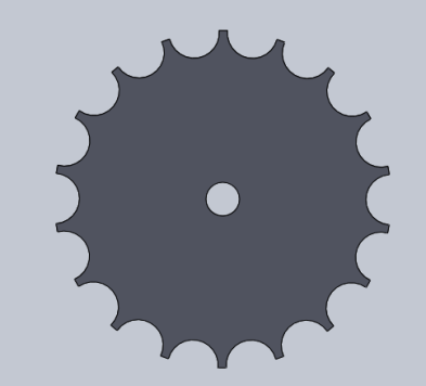
The geared design:
- We were able to be creative and adjust the design to our needs.
- The gear movement need some adjustment since the prototype walked only straight. we added a motor to control each side of legs.
- By adding the motor we were able to compile the moment of the spider. When we turn off the right motor the spider turn right and vice versa.
- Less part to print and they all were able to print with precision
- We could of used different method like laser cutting to get some parts but the 3D printing time was enough for our requirements.
- The Solid work design level of complexity was little bit higher than the formation and help provided by the division for the manufacturing engineer but not as high as the level of complexity of the Hex bug design.
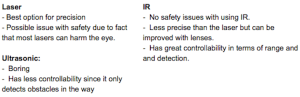
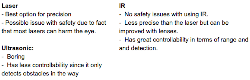
Tagging System (interactive game)
For the interactive game we had 3 options : Laser tag, IR tag, and Ultrasonic. After doing research on each option, we settled with IR tagging system for its safety. In the pictures below, some arguments about why we choose the IR are shown:
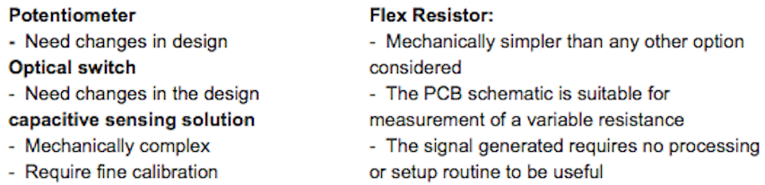
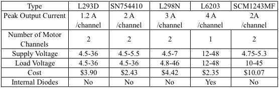
Motor Control
After assembling the 3DoT David, we found that the motor synchronization is optional. The leg position helped the robot to move forward even if the motors are not in sync. Before that, we looked at different possibilities on how to synchronize the two motors and it is shown on the table below:

We ended up choosing the Flex resistor. After implementing it to our robot we found that there is a slight improvement when the spider movement was more in sync. However, we decide to remove the flex resistor with the agreement of the customer because of the limited improvement and the limited number of pins available on the 3DoT board.
Innovative Design Solutions
In every step of assembling the 3Dot David, the team discovered issues. By brainstorming ideas, solutions are found and implemented into the design.
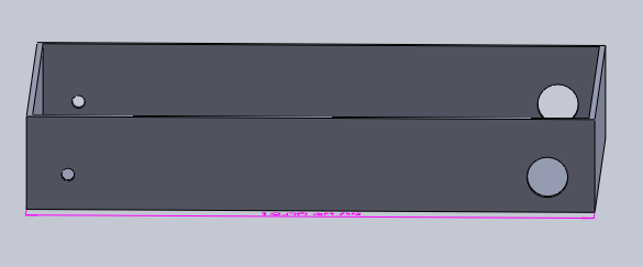
Design Evolution
With the solutions found, legs, bottom plate, and top plate are adjusted in Solidworks. By adjusting the parts, the 3Dot David will be able to move freely as it accomplishes its mission.
Design Evolution (for more details click here to go to the blog post) :
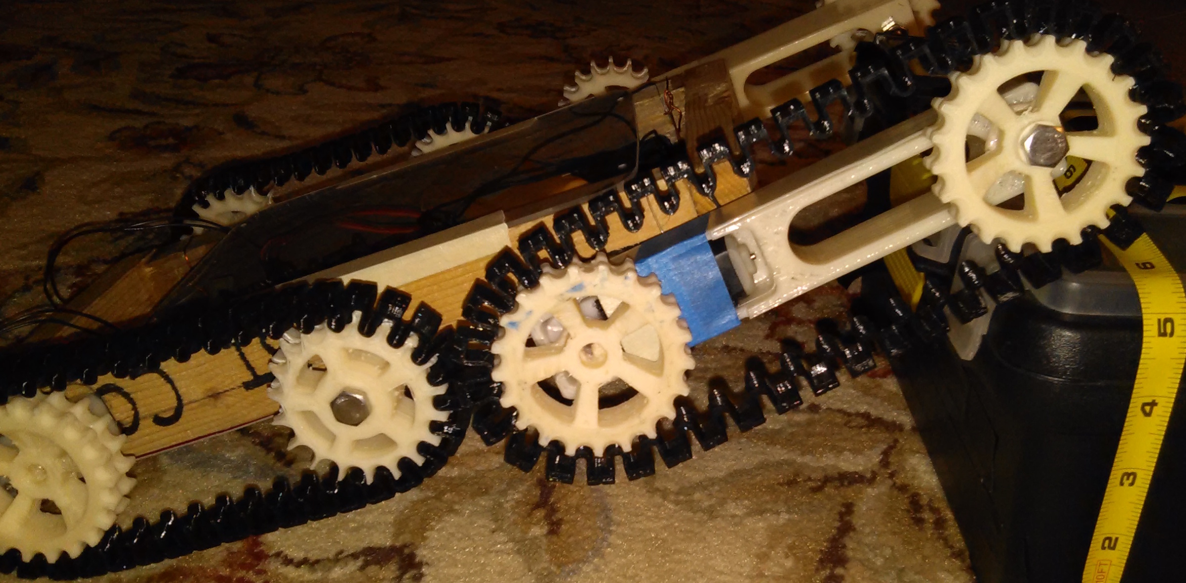
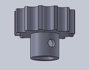
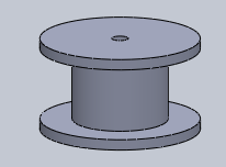
Gear Instability
Three tests were made in order to obtain stability for the gears moving the legs as it rotates. The first test was putting screws inside the center hole of the gears, but the screws were heavy affecting the motion of the gear. The second test was implementing white gears into the rapid prototype made of wood. The motors worked perfectly with these gears. However, the gears were too light, which causes concern when inserting the leg on the gear. The issue was solved by implementing extrusions on the testing board in the third test.
Gear Instability (for more details click here to go to the blog post):
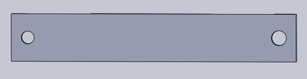
Joint Solution
In order for the leg to rotate freely, the joint must be lightweight plastic material. The joint was made in solidworks. The concern about it is that making a connection to secure the joint to the gear. A second solution was made by inserting a tube as a joint. However, there is much labor in sanding the tubes. A joint solution is found by using one of the parts in the white gear bag for the legs to rotate freely.
Joint Solution (for more details click here to go to the blog post)
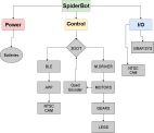
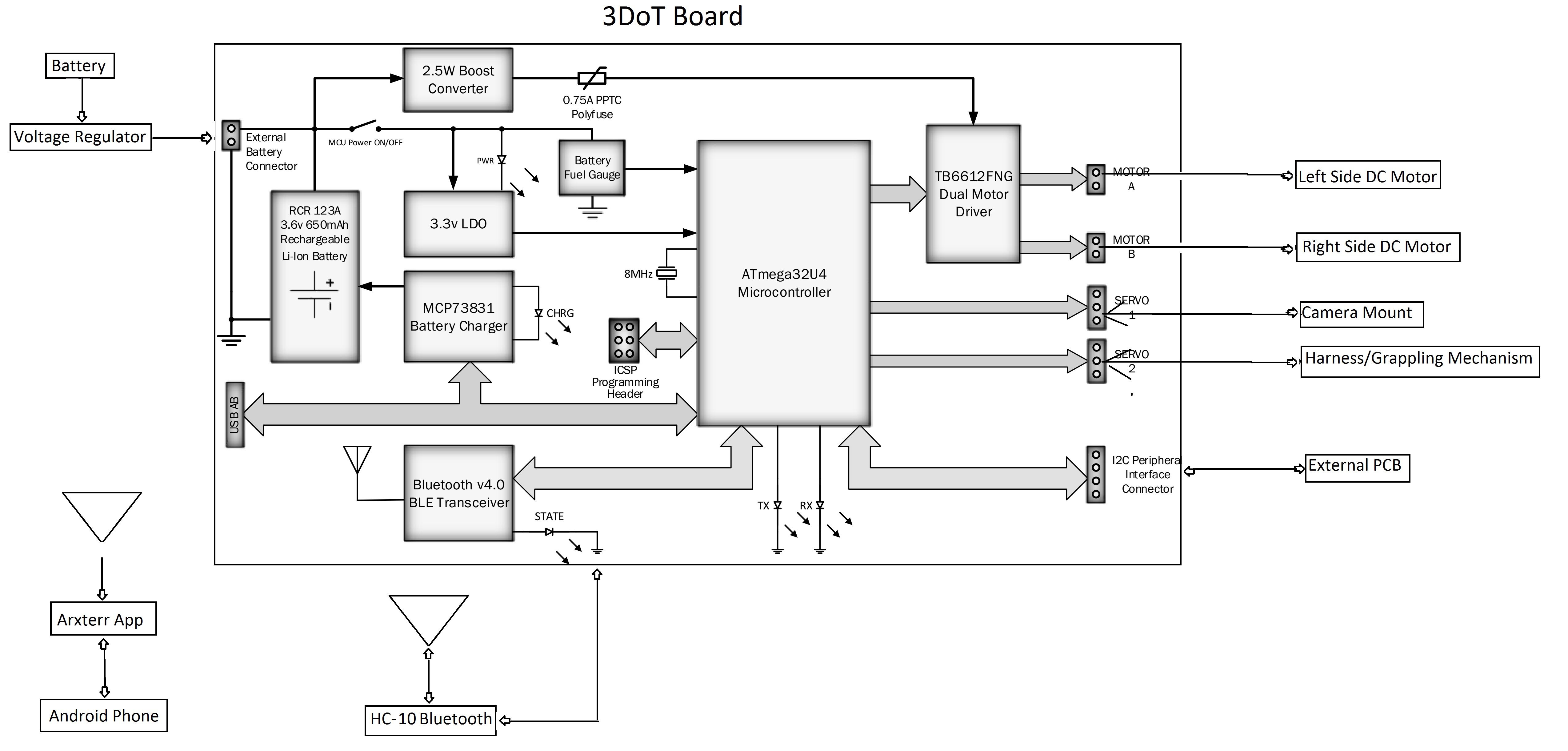
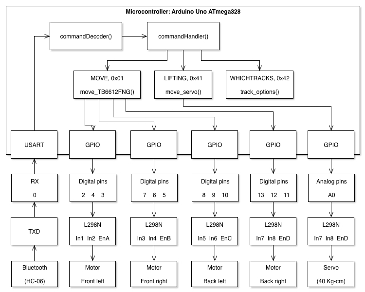
System Design
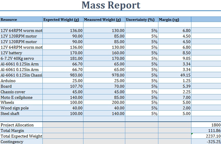
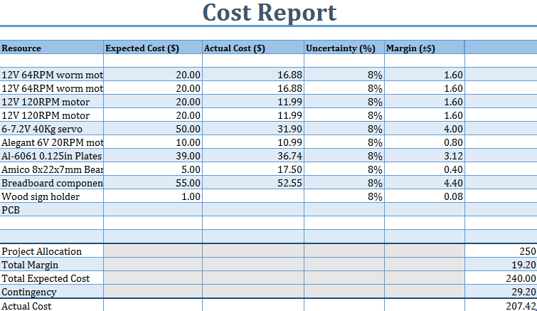
The system design for the 3DoT David is explained in detail in the following blog post. The system block diagram, interface definitions, and system resource reports are all presented there.
System Design (for more details click here to go to the blog post):
If you want to be directed to a specific topic in the system design blog post use the links below:
Trade-off studies
IR Trade-off Study
This study shows off the emitters and detectors relevant to our project according to specifications made by the electronics and control engineer. There is a table with the specs of emitters and a table with specs of detectors.
IR Trade-off Study (for more details click here to go to the blog post)
Servos and motors trade-off study
This trade off study was conducted in order to determine the best way to control our spider’s walking movements. There are brief descriptions of what motors and servos are, and how one may work better than the other for our project.
Servos and Motors Trade-off Study (for more details click here to go to the blog post)
Experimental Results
Leg Movement Angle Study
Calculations are done to find the distance of the final lift of the leg attached to the gear from the surface by using trigonometric equations. The leg must be lifted in order the spider to walk. If the leg is not able to lift, the spider is not going to walk. Thus, a blocker is created to make the leg lift as the gear rotates 360 degrees.
Leg Movement Angle Study (for more details click here to go to the blog post)
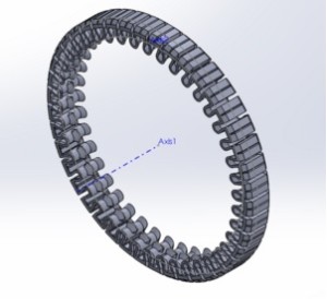
Gear Train
The gear train is an important mechanism for the 3Dot David that keeps it moving from place to place. Calculations are done to get the reasonable rotational speed of the gear by finding the gear ratio and using the given rpm of the motor at 120 rpm, or 2 cycles per second with the large gear.
Gear Train (for more details click here to go to the blog post)
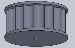
Cam Simulation
The first prototype is made with a Cam Simulation simulated in Solidworks. Further details to every part are explained in the CAM movement system. However, the design proved to be complex, and it could exceed the 6 hour limit printing time. The CAM simulation had many mates and crashed because of it.
Cam Simulation (for more details click here to go to the blog post)
IR Lens Study
This study was conducted to determine a lens for increasing the range of the infrared emitter to meet the game requirement of 5ft. We will see the various types of lenses as well as calculations for the physics of light through lenses. The conclusion shows what
IR Lens Study (for more details click here to go to the blog post)
Motor Driver Control
This blog post explains how we controlled the motors from the sparkfun Pro Micro using the sparkfun TB6612FNG motor driver. It includes screenshots of the code being used with the sparkfun Pro Micro board to drive PWM signals for how fast the motors should rotate, as well as test functions for turning left, right, and reversing.
Motor Driver Control (for more details click here to go to the blog post)
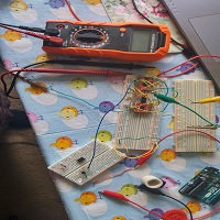
IR emitter/detector testing
These are the test results of the IR tagging system done by connecting the schmitt trigger, BJT, emitter, and detector circuits. We show how the range is affected as we increase certain resistor values as well as the voltages being read from the output of the schmitt trigger and IR detector.
IR emitter/detector testing (for more details click here to go to the blog post)
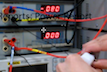
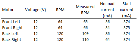
3DoT Board motor Current Safety Test
Since there was a change with the mechanical design of our spider, there was the issue of the old motors not being able to rotate the new gears. Therefore we needed to search for motors that were strong enough to turn the gears. The solution to the problem was to use geared motors, which are motors with a gear train that reduces their speed while increasing the torque. However, with this increase in torque, there is also an increase in how much current the motors would demand. We conducted a comprehensive test to show that the current would not exceed 450mA, where the results are stored inside of tables.
3DoT board motor safety test (for more details click here to go to the blog post)
Subsystem design
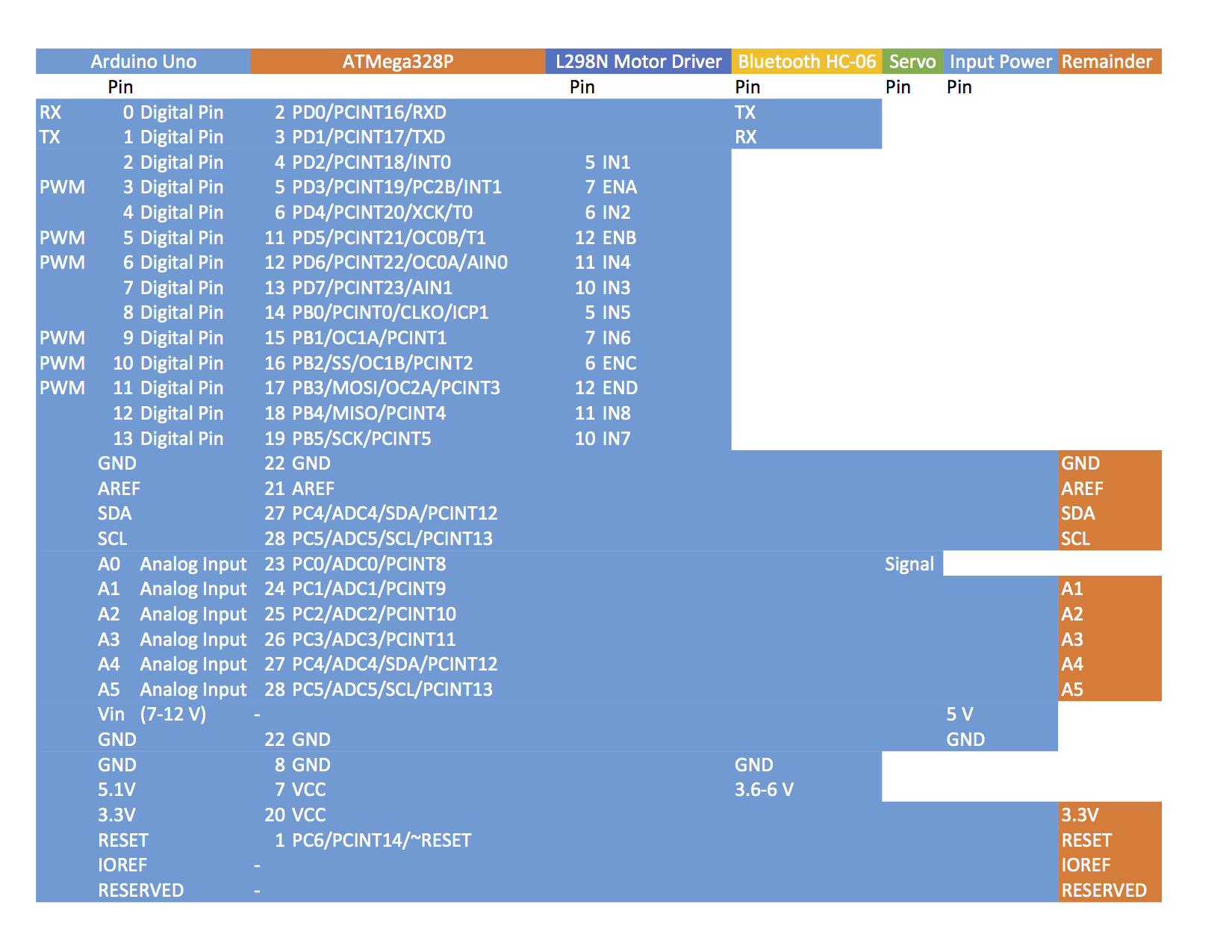
Interface definitions


This matrix describes how each subsystem will be connected to the main controller (Atmega 32u4) and what those pins are referred to on each respective system. This is covered in more detail in the system design blog post.
System Design (for more details click here to go to the blog post)
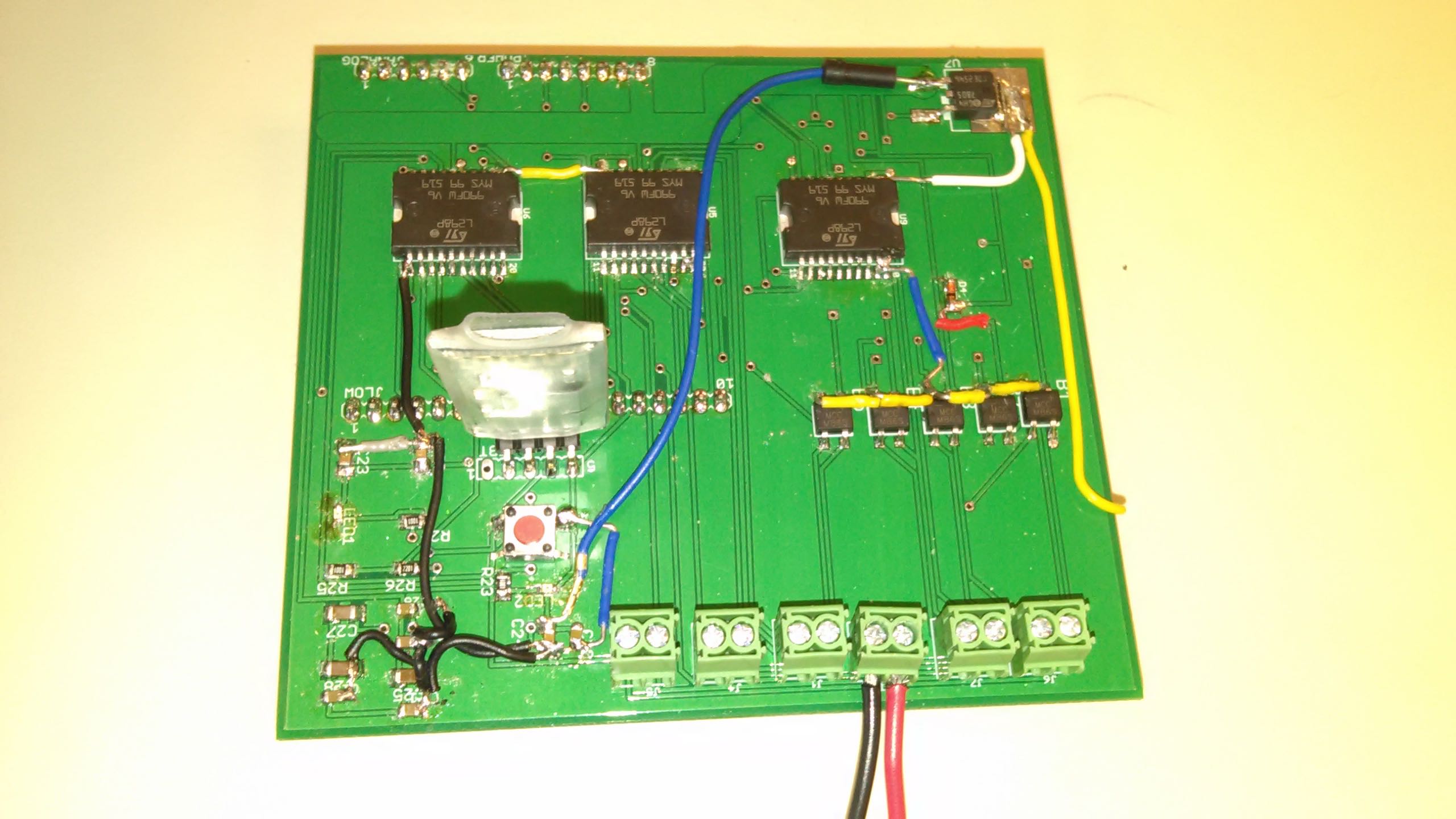
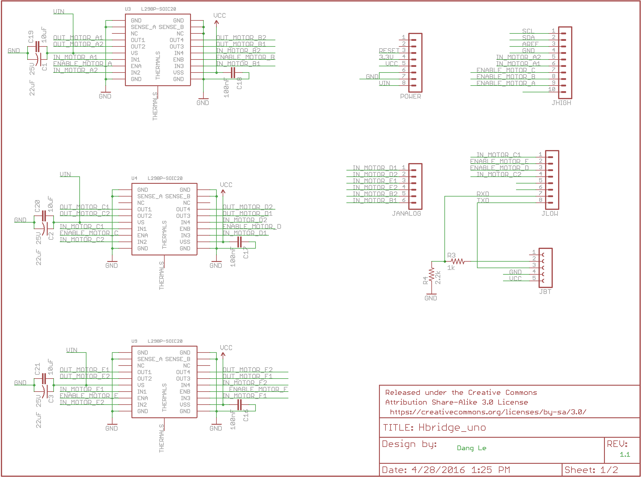
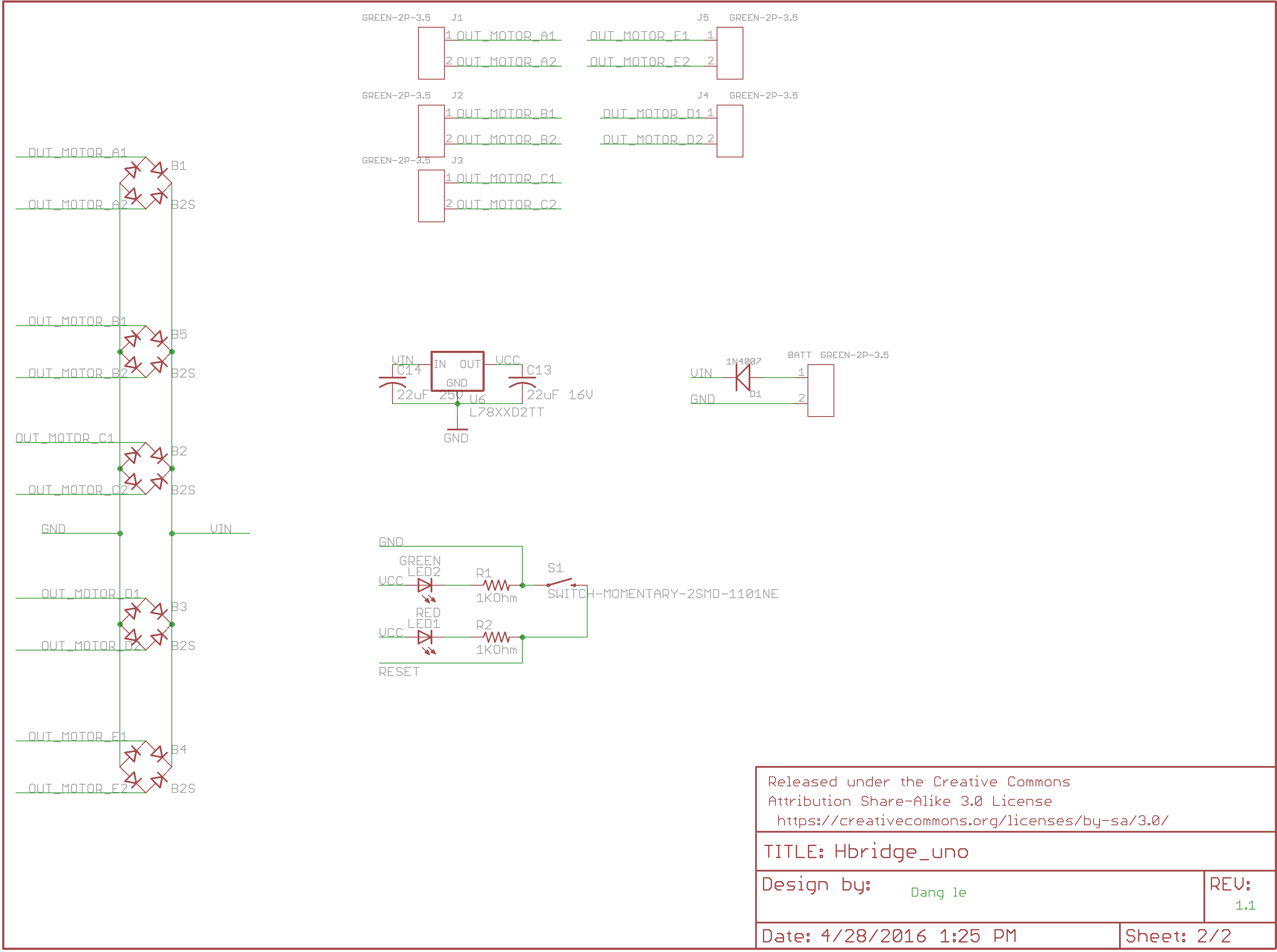
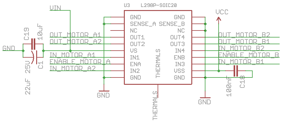
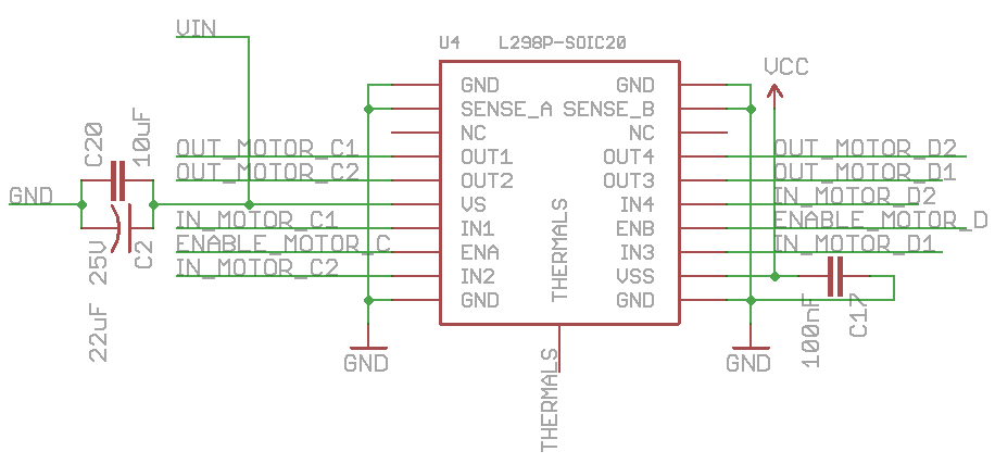
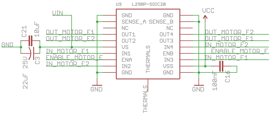
Custom PCB Design
The PCB design includes a signal processing circuit, a BJT to drive current to our IR emitter, a speaker, and voltage buffers. Each circuit is thoroughly explained in the PCB design blog post
PCB Design (for more details click here to go to the blog post)
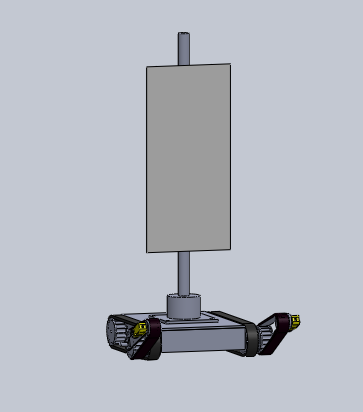
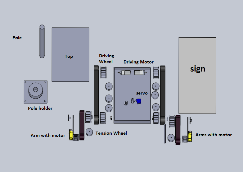
Hardware Design
The Solidworks simulation folder has all the parts to simulate the 3Dot David. The adjusted parts for the Final David are the parts adjusted to solve issues as the team assembled it during the process.The mechanical design is explained in the link below:
Hardware design (for more details click here to go to the blog post)
The STL files are to be physically printed from Solid Work. The link below contains the zipped STL files:
Final STL files (click here to access files)
Software Design
The software design for the 3DoT David is explained in detail in this blog post. It goes into depth about the individual modules and what the software has to do.
Software Design (for more details click here to go to the blog post)
Additionally, the specific changes to the Arxterra firmware as the project progressed are covered in the following blog post. It provides information on the addition and removal of code to accomplish the tasks laid out in the software design blog post.
Arxterra firmware configuration(for more details click here to go to the blog post)
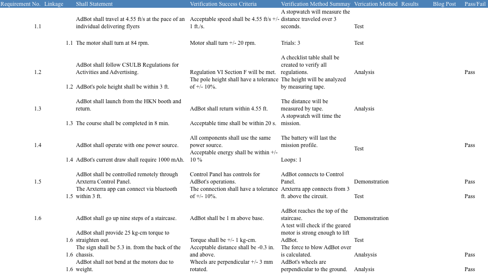
Verification and Validation Documents
In order to prove that the desired product was built properly and achieves its purpose, verification and validation must be done. The verification and validation matrices lists the requirements related to the tests that must be performed and their results. Those documents can be found here.
Verification matrix (for more details click here to go to the blog post)
Validation matrix (for more details click here to go to the blog post)
The verification and validation test plans provide all of the instructions for the tests to be performed and can be found here.
Verification test plan(for more details click here to go to the blog post)
Validation test plan (for more details click here to go to the blog post)
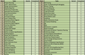
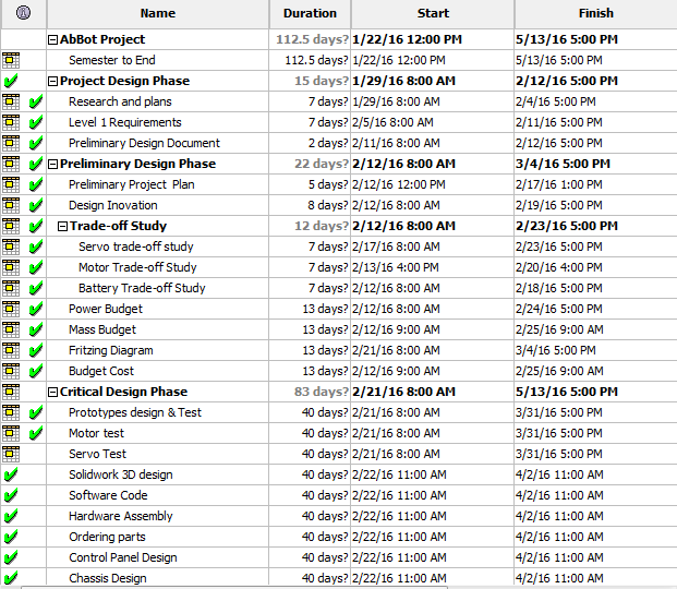
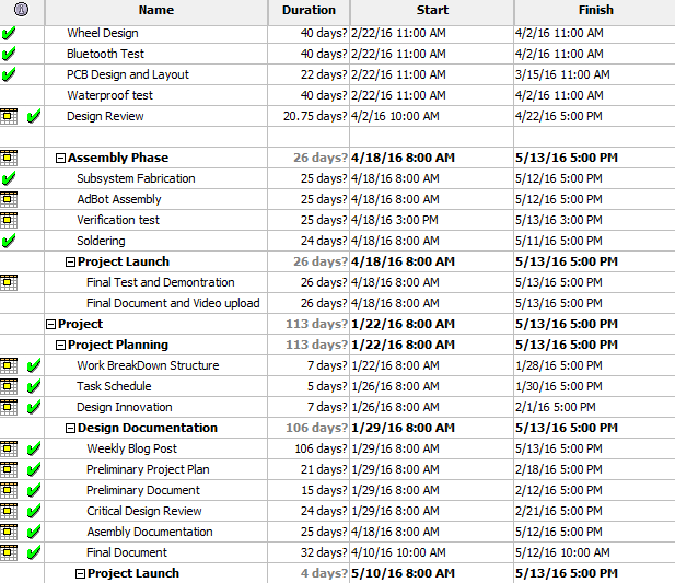
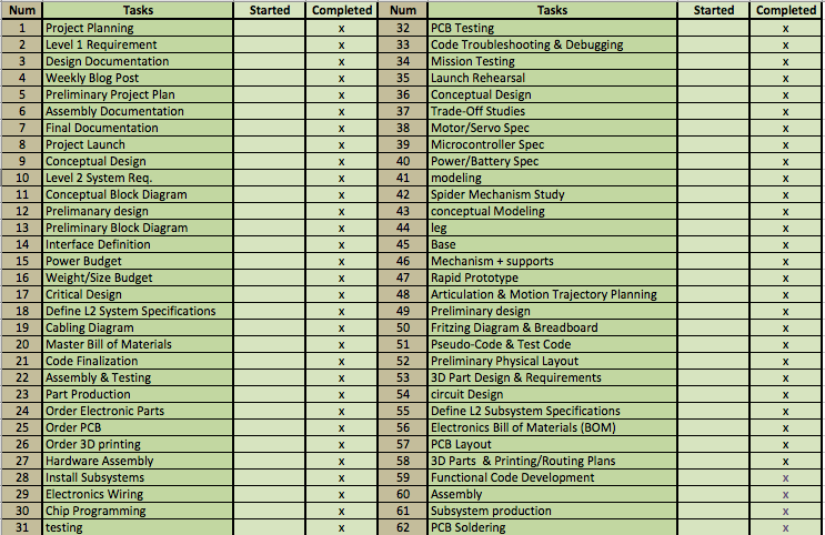
Project final status
The picture below shows The table of task and status of completion. The important tasks were taken from the project schedule presented already on the CDR and PDR, Those tasks were used to build the the project percentage completion graph and burn down graph.
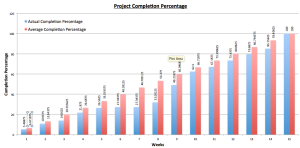
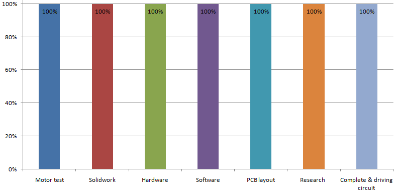
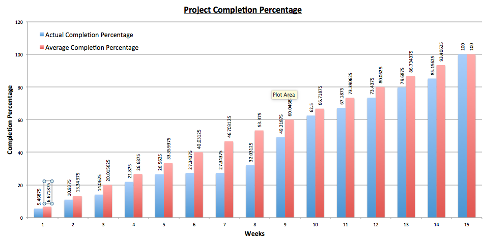
Completion %
The graph below show the average Vs. the actual completion percentage by week during the 16 weeks of the semester.
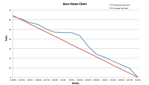
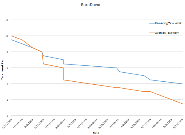
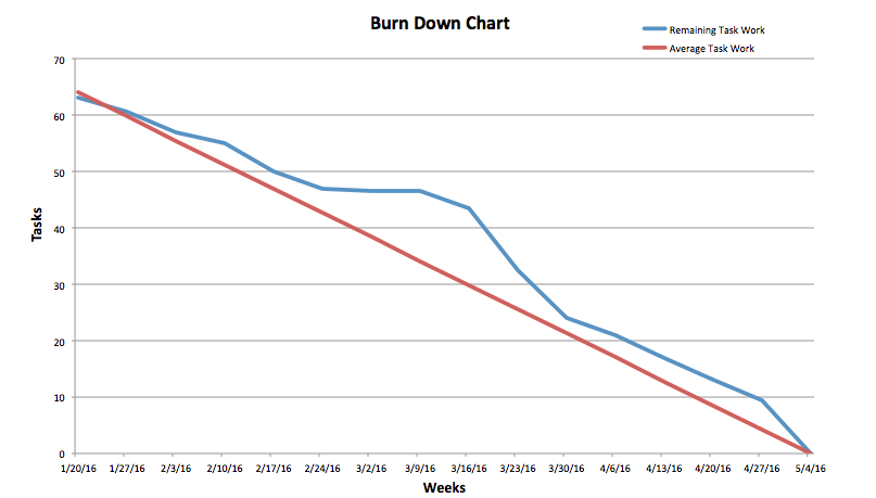
Final burn down
The graph below show the average Vs. the actual task completion graph by week during the 16 weeks of the semester. As asked, when the teem start a task we mark it as 50% completed and when the task is completed we add another 50%.
From the burn down graph we can see that from week 6 to 8 our project was delayed because of issues of the old design. After week 8, we began working on the new design and we are able to recover the lost time.
Previous Project Blog Posts:
The following Table of Contents blog post was created to organize all of the blog posts for our project and make it easier for future students to access resources related to their role.
All the blog posts made 2016 3DoT David spring semester by department (click here)
Concluding Thought
I found that the project manager position is the most stressful position in the 400D class since our grade is relies on the outcome of the project. But through this post. There were a lot of things that I had to learn on my own and I would have appreciated it if there was some kind of training plan for project managers. Additionally, I would have liked to be able to sit in on the training sessions for the other divisions, so that I could have a better understanding of what they were working on.
Issues encountered :
- I would advise to choose the right design from the beginning of the semester: our project start was very stressful during the first 8 weeks and that was due to the design that was assigned to us. The mechanism and the shape design was complex for a beginner in solid works specially if they could not get any useful information, which i think it was the division manager part.
- Improve IR range: It took both teams time to decide what type of tagging system to use between Laser, IR, LED and other than that the we couldn’t find a fast shipping for the lenses which delayed us more. We would have liked more time to test the IR tagging system before the due date
- Size of the Spider: After searching different kind of gear, we decided to use gears that will give us durability and stability unfortunately they were a little big. If we were able to find smaller gears we would of reduced the size of the spider
If we went back in time, other than applying for a division manager position, i would have chosen to implement the Jerry Mantzel mechanism instead of the Hex Bug mechanism that was provided.
Resources links
- Project Video
- CDR Powerpoint
- PDR Powerpoint
- Project Libre File
- Verification Matrix
- Verification Test Plan
- Validation Matrix
- Validation Test Plan
- SolidWorks Files:
- Frizting Files
- EagleCAD Files
- Arxterra Firmware Code


