By: Eduardo De La Cruz (Project Manager and Manufacturing Engineer)
Approved by: Miguel Garcia (Quality Assurance)
Since we decided to model 3DoT Hexy of Spring 2016’s 3DoT David, Prof. Hill recommended that we get in contact with the owner of 3DoT David to have access to the robot. Luckily, we were able to get in touch with the owner and were permitted to use the robot as a reference. From 3DoT David, we have learned a lot about: movement dynamics, overall dimensions, and weakest points in the structural design. In this blog post we will highlight the weakest points in the structural design of 3DoT David and provide solution that will be implemented in our design of 3DoT Hexy.
- In order to minimize manufacturing cost, and packaging cost the robot shall be able to be constructed from subassemblies within 10 minutes
- For quick production of the prototype, the preliminary project shall be restricted to six hours of total printing time with a 2 hours limit for each single print
- The robot shall be designed in such a way that there are no dangling or exposed wires and the final fabrication is pleasing to the customer
- To keep cost down, and keep as a toy aspect , the robot shall use only 2 micro motors to drive the movement of the robot.
- The spiderbot shall have an allocated budget of $250, however to compete with the existing robot toy market we shall try to minimize the cost of production as much as possible.
According to Chris (one of the engineers behind 3DoT David) 3DoT David’s cam system has a tendency of “gear popping”. This means that at high speeds the gears tied to the shafts slip off. To solve this problem the 3DoT David team relied on melting the tips of the shafts to prevent the gears from lifting. This also was a problem for the gears tied to the motors which could not rely on the previous solutions do to having a steel shaft. This solution solved the gear popping problem, however, it complicates the mission task involving assembly and disassembly. Below are images of how it looks:
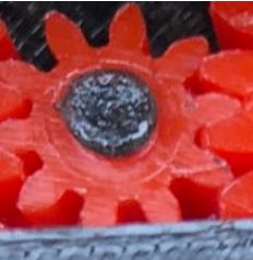
Figure 1: Old gear capture design
Caps for gear shafts
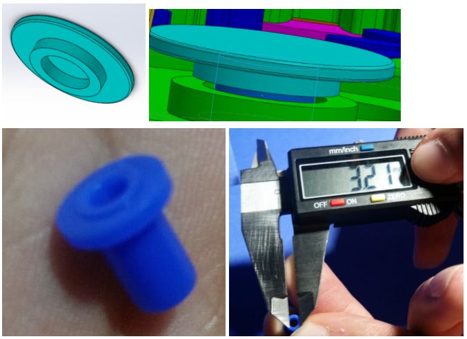
Figure 2: Gear Capture solution
To solve this problem we decided to use caps obtained online from a different gear set. The caps have a diameter of 3.2 mm which will be the diameter of the shafts we will use in order to ensure we have a tight fit without heating or gluing. This will make our cam system easier to assemble and disassemble.
Top shaft to prevent gear tied to motor from popping:
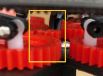
Figure 3: Old design: Nothing prevents the gear from popping off
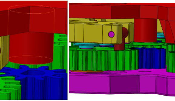
Figure 4: Gear capture solution for driving gears
We will incorporate a shaft positioned over the driving gears that will be part of the 3D print of the top panel. This will keep the driving gear from coming off.
Gear to motor shaft connection
3DoT David relied on gears that have a bore greater in diameter than the shaft diameter of the motors. The solution the 3DoT David team used to solve this problem was to insert a piece of a pen tube into the bore to provide a tight fit. The problem with this solutions is that there is no real mechanism that locks the gear to the shaft to prevent the gear from slipping from the shaft.
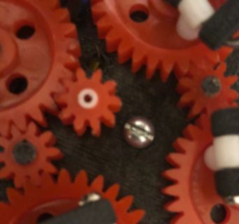
Figure 5: Old driving gears Motor shaft held to gear bore via the use of a cut piece of pen tubing.
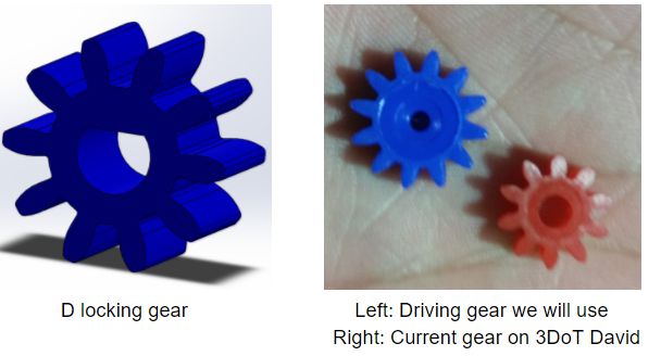
Figure 6: New driving gears
The motor shaft has a D shaped shaft, therefore using a gear with a D shape bore would lock the gear to the motor shaft. Luckily, our manufacturing engineer was able to find gears that have the 10 mm pitch diameter for our driving gears with a smaller bore, as shown above. This means that we can cut out the D shape using a dremel tool or other precision cutting tool.
3DoT David’s Lifting mechanism works well in thrusting and lifting the spider forward, however, the amount of lift of the current design is proportional to the length of the femurs. Since we want to reduce the overall width of our robot (to give it a better aspect ratio relative to a 4”x 4” maze room), figuring out a way to reduce the length of femurs while providing an acceptable amount of lift is desirable.
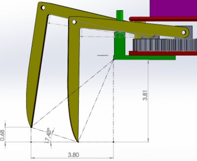
Figure 7: Old leg design, note: units = cm
Solution:
We decided that integrating the lift mechanism into the femurs of the legs would give us more control over the lift angle (since it will be based on the angle of the contour we define), as well as reduces the width of the robot since femur lengths can be reduced and will eliminate the need of the protruding lift mechanism. As an added extra, we also expect to see reduced 3D print times for the femurs.
Our solution involves re-designing the femurs and the base to have a guide that will increment the angle of the femur as the femur rotates outward, providing lift. How it works:
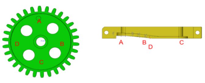
Figure 8: Gear-to-Femur relation
At point A the femur should be touching the floor and preparing for thrust. At point B, the femur begins ascending. At point C the femur is at its peak lift. At point D, femur is descending.This solution enables us to control the lift of the legs based on the angles of the femur contour. The guide that the femurs will follow will also have an angle to provide a smooth transition from point A to point C. As shown below:

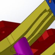
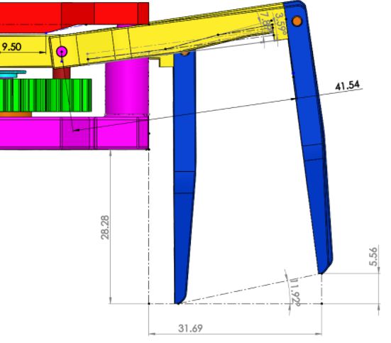
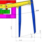
Figure 9: New leg design
As can be seen above, the length the leg extends is 31.69 mm from the chassis, compared to 3DoT david’s 38mm leg extensions our leg design will reduce the overall width of the robot by 2*(38mm – 31.69mm) = 12.62mm. Our legs will have a lift distance of 5.56 mm which is 1.24mm less than 3DoT David Design. Also note, the top panel will have a protrusion that will keep the legs down when they are in there innermost point to keep them grounded as can be seen by the image above in the upper left corner. The height of our robot will be 28.28mm vs 38.1mm therefore our design will be 9.82mm lower meaning we should have a better reading for our sensors.
Below are the calculations for our leg’s profile. Note, calculations for determining our leg profile were obtained from Spring 2016 3DoT David Leg Movement Angle Study.
Circumference of femur tied to gear:
C = 41.54 mm
Initial Lift do to inner contours:
7.89 deg – 3.59 deg = 4.3 deg
sin(4.3) = x/41.54
x = 3.12 mm
Final Lift Obtained = 11.92 deg
41.54 mm * sin(11.92 deg) = 8.58 mm
8.58 mm – 3.12 mm = 5.46 mm of lift of the ground
From our actual results, we can see that our design is .1 mm of the actual Lift.
If we wished to modify the height clearance of our design we would just change the value of the initial lift by changing the angle of the leg contours.
3DoT David’s leg joints where not a pretty sight to the eye. Since the design relied on a single contact point for the femur to tibia joint, 3DoT’s joints would loosen and become flimsy as the robot walked. The solution the 3DoT david engineers had was hot gluing the joints to make them stick together better (as shown below). However, this beats the purpose of the assembly and disassembly portion of the mission. To solve this problem we decided to redesign the leg joints to have more contact points.
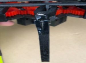
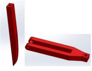
Figure 10: Old legs and femurs
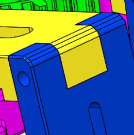
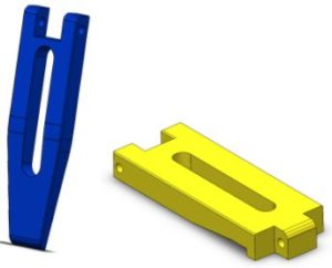
Figure 11: New leg design
By implementing this design, we had to redesign the tibias to give the joints 5 contact points. This will make the joint more sturdy. To prevent the joint from being a flexible joint, we will thread the hole the hole shown in the image above and insert a screw across to prevent the joint from moving the femur and tibia.
Purpose: Provide a path for wires from top panel to bottom panel that does not protrude out of the robot or interferes with cam movement.
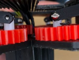
Figure 12: Old design -Wires are wrapped in electrical tape and are susceptible to interfere with gear rotation.
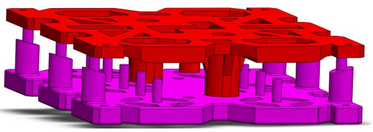
Figure 13: New design
Wires will have an isolated passage from top to bottom panel through two different apertures. Both holes will will have an 8 mm diameter opening giving plenty of space for all wires that will be connected to components on the underside of Hexy.
Redesigning top and bottom panel
We will be re-designing the top and bottom panel to accommodate new design changes made from old design review. We will also take this opportunity to give Hexy a unique appearance different from that of 3DoT David, and try to improve on reducing 3D print times.
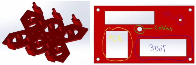
Figure 14: Old design
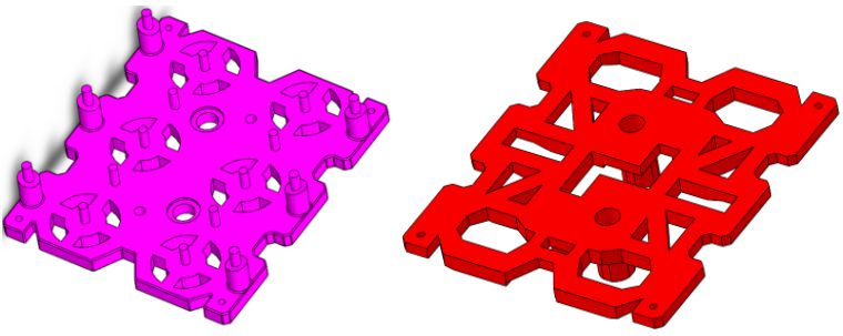
Figure 15: New Design
For the bottom panel we will fit gear lift guides into the chassis instead of having them stick out like in 3DoT David’s design (as explained in the lift mechanism section). We will extrude cut patterns in top and bottom panel to reduce 3D print times while at the same time giving our design a symmetric and appealing view. Top and bottom panel will have holes for the wire management and for the driving motor connection. The design will have more holes upon determination of the position of the custom PCB board, battery, and 3DoT board
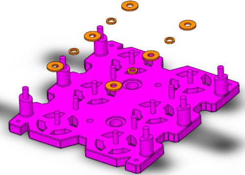
Figure 16: Adding washers
3DoT David didn’t see the need of adding washers to reduce friction, however we will incorporate washers along with grease in order to reduce friction between the gears and the chassis.
- https://www.arxterra.com/spring-2016-3dot-david-design-innovation/
- https://www.arxterra.com/3dot-david-rapid-gear-instability/
- https://www.arxterra.com/3dot-david-rapid-joint-connection-between-gear-and-leg/
- https://www.arxterra.com/3dot-david-leg-movement-angle-study/
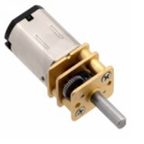
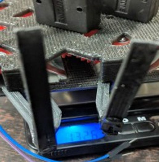 Figure 1: 3DoT David Weight
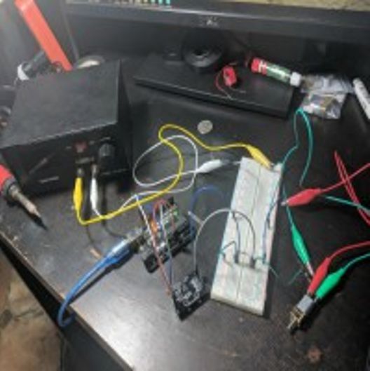 Figure 2: Current Measurement
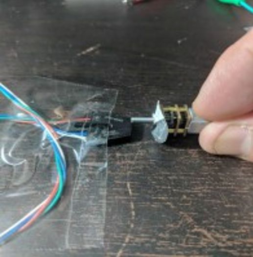 Figure 3: Calculating RPM
 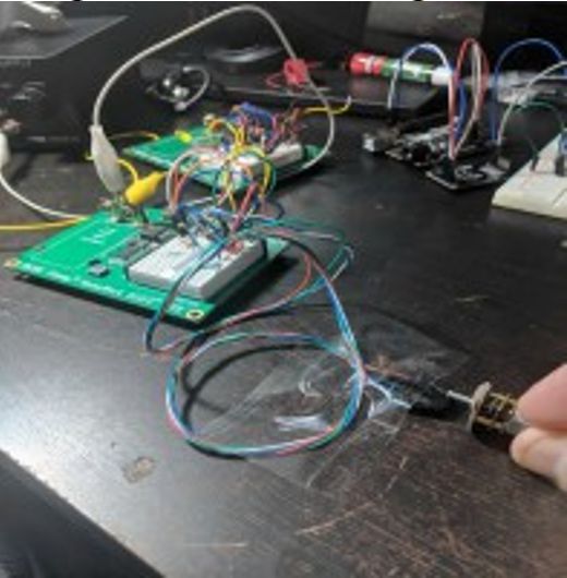 Figure 4: Full RPM measurement set-up
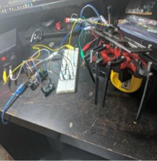 Figure 5: Current measurement with load
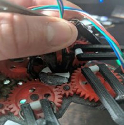 Figure 6: RPM measurement with load
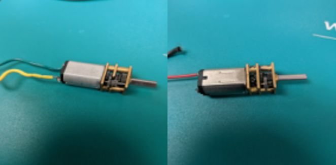 Figure 7: Micro-motors from resource cabinets
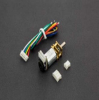 Figure 8: Purchased Micro-motor
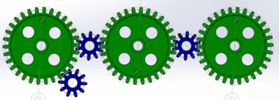
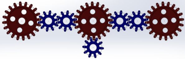
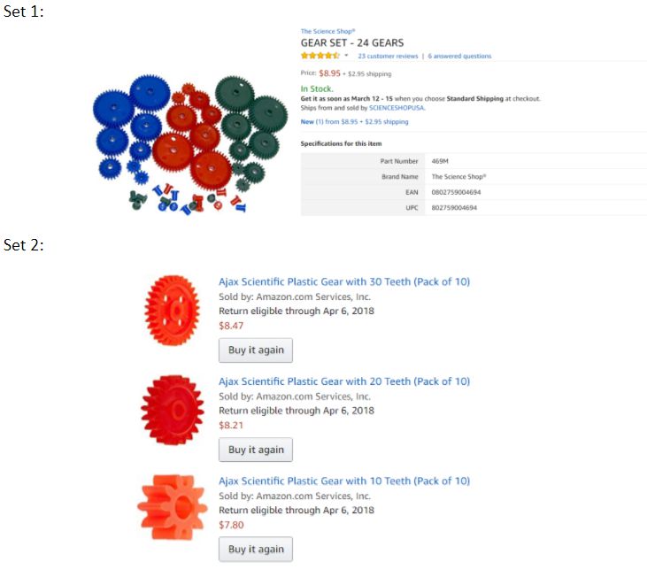
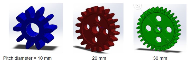
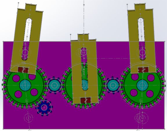

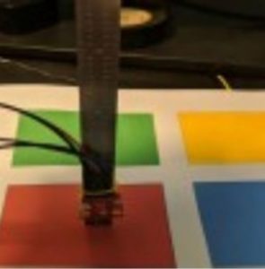 Figure 2: Set-up for measurements