Goliath Fall 2017 – 3DOT 4.54

While waiting for the new 3Dot board (5.03) the 3Dot 4.54 version board is being used for development. Physically the boards are nearly the same. The only major change that affects us is the placement of headers and connectors. On the new board, there are two separate locations to connect I2C devices. So, our devices can route […]

Goliath Fall 2017 – Breadboarding

All major components have been laid out on a breadboard for testing the majority of the program work. Most importantly being the color sensors and gyro. As both provide vital functions for navigating the maze. This breadboarding has provided very useful as the previous Goliath has been used as a test platform with room for new components on top. […]

Antenna Matching

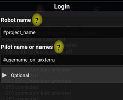
Written by Zachary de Bruyn (Electronics & Control)
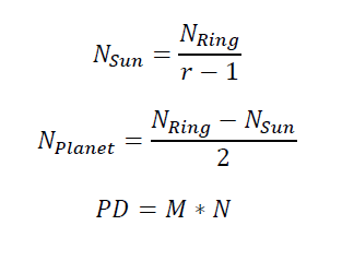
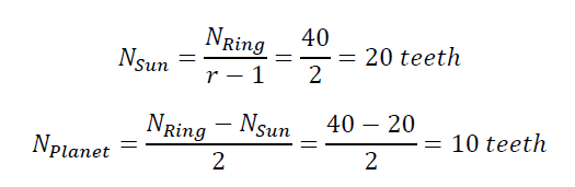
Table of Contents

Purpose

The PeteBot chassis team is unique in that it is utilizing two PCBs which operate on two different MCUs; the first being the heritage 3DoT v5.03 board which uses the ATMega32U4, and the second being the SAMB11, which incorporates the ATSAMB11. One significant different between the two boards is that the SAMB11 has a transceiver module. Because the SAMB11 can operate with the incorporated Bluetooth (BLE), an antenna network was needed to be designed to utilize the BLE transceiver. Because an antenna network was needed to be constructed with minimal input from the SAMB11 reference design, many steps were required to be performed in order to ensure that the SAMB11 could operate at the 2.4-GHz BLE frequency.

Antenna Selection

The first step in the overal process of incorporated a matching network is selecting a proper antenna based on the needs of the system. To reiterate, the operating frequency of BLE is 2.4-GHz. Along with frequency requirements, there are also size requirements. Our antenna therefore was required to operate at the BLE frequency, to be small enough to fit on a PCB, and to operate the PeteBot chassis. These requirements alone narrowed the possibilites of two types of antennas: PCB or chip antennas. With the PCB antennas, one antenna that looks promising is the meandered inverted-F antenna (MIFA). The chip antenna resembles a 0805 resistor or inductor. The two antennas are shown below:

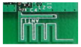
Figure One – MIFA (Source: Cypress)

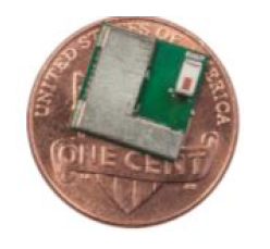
Figure Two – Chip Antenna (Source: Cypress)

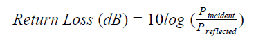
Analyzing both types and data sheets of antennas, we discover that both antennas have an isotropic radiation pattern, meaning that the frequency of the antenna can be picked up equally from almost every direction. This is ideal for our applications due to the fact that the PeteBot will be required to operate via RC mode by an operated. A few other important antenna parameters are: return loss, gain, and bandwidth. Return loss is essentially how much of the power being transmitted is reflected due to the mismatch of the antenna’s imepdances. The standard for impedances is usually 50-Ohms. A return loss greater or equal to 10-dB is considered ideal for operation [1]. Referring to the following equaltion for return loss:
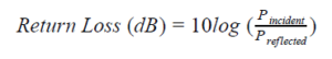
Equation (1)

At a return loss of 10-dB which translates to 90% of power transmittered going into the antenna, return loss of 20-dB translates to 99%. The gain is a measure of ow strong the radiation field is compared to the ideal omnidirectional antenna. For isotropic antennas, like that being applied to the PeteBot, gain is measured as dBi. The “i” simply indicates that the gain is measured frerence to an istropic antenna. While the MIFA antenna has a gain of about 5-dB depending on the plane of radation, the chip antenna has a peak gain of 0.5-dBi. The bandwidth requirements for the antennas requires that the BLE frequency is capable of interception, which was 2.4-GHz. The chip antenna has a frequency range of 2.4- to 2.5-GHz, which translates to a bandwidth of 100-MHz. The MIFA antenna operates a a comparable frequency range, and therefore has an equivalent bandwidth.

With comparable operational characteristics, an antenna selection for our purposes was based upon flexibility, in which the antenna can be used in a variety of configurations for the SAMB11 board. In the case of the PeteBot SAMB11 PCB, the chip antenna is the best candidate.

Matching Network

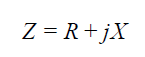
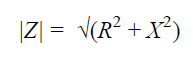
The purpose of an antenna matching network is to allow the most power to be delivered to the load. The load in the case of transcievers, like the SAMB11, is dependent on whether the antenna is transmitting or receiving. If the antenna is transmitting, then the antenna is the load, whicl the SoC SAMB11 is the load if the system is receiving. It is common practice to design a load with 50-Ohm impedences for RF traces [1]. As a review, the term impedance is mathematically defined as the magnitude of resistance and reactance. It is typically denoted by the letter “Z.”

Equation (2)

Equation (3)

In Equations (2) and (3), R denotes resistance, and X for reactance. Both values are measured in Ohms.

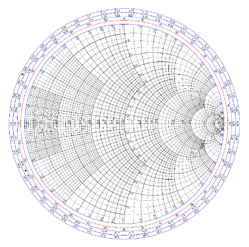
Now that impedance is defined and the typical characteristic impedance is defined as 50-Ohms, this information can be used in collaboration with the helpful tool called a Smith Chart.

Smith Chart

It is a graphicaly tool used to help plot complex impedances and used to define a matching network. It is also helpful in determining many important RF parameters, including VSWR, return loss, reflection coefficient, and transmission coefficients. Using this chart can design a matching network.

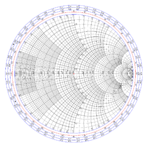
Figure Three – Smith Chart (Courtesy of Wikipedia)

There are a lot of reference towards using Smith charts on YouTube that will explain how to find the difference parameters.

The best usage of the Smith chart is to be able to measure the input impedances going into a load, where the input impedance is defined as Z_in. Character impedance is Z_0 and the load impedance is Z_L.

As an example, let’s say that the measured Z_in was 100-j100-Ohms. The first step would be to normalize the input impedance by dividing Z_in by Z_0, which would result in 2-j2-Ohms. This opint can be located on the Smith chart, and from this point (2-j2), you can use a combination of inductors and capacitors to move the impedance to the necessary location on the Smith chart, which is the center of the chart where the red dot is in Figure 3. The table below helps better understand how each component affects the impedance of the matching network.

Table One

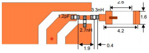
Using any combination of passive elements can be used to get measured impedance as close as possible to the center of the Smith chart for optimal performance. If we refer to the matching newtorks in Figure 4 and Figure 5, we can see that the matching network consists of the passive elements described in Table One.

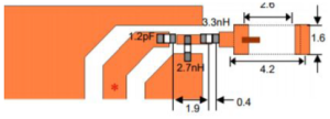
Figure Four – Chip Matching Network Antenna Reference Design

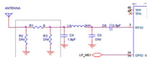
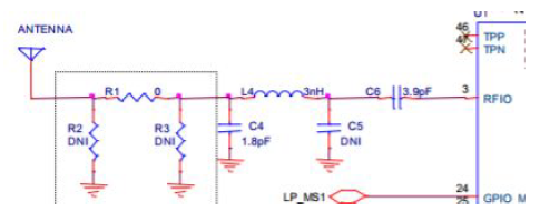
Figure Five – SAMB11 Matching Network Reference Design

Figure Five depicts the matching network reference design for the SAMB11 where the resistance network shown in the dotted square is omitted from the final design PCB. Also omitted was the capacitor laveld DNI (Do Not Include).

S-Parameters

Scattering parameters, or “S-parameters” are a set of parameters which define the electrical power delivered between two ports on a network, where a port is any where within the network containing voltage or current delivery [6]. The four parameters are displayed below:

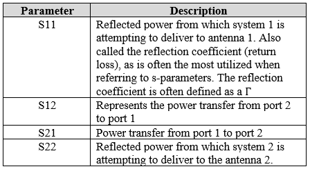
Table Two – S-Parameters

The reflection coefficient referred to in the S11 description is defined as followed:

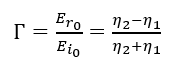
Equation Four – Reflection Coefficient

Where  are the reflected and incident plane waves, and the  is the intrinsic impedance of the medium the wave is traveling through, and  is the intrinsic impedance of the surface/material medium the wave reflects or penetrates [5].

The S-parameters can be collected by using a Vector Network Analyzer, however they are fairly expensive, usually greater than $10,000 on the lower end models. As a substitute, there is software such as Microwave Office or Optenni which can calculate the S-parameters as well. While these software suites are NOT free, they do offer free “research” trials where you can use it free for a week (Microwave Office) or for a month (Optenni).

Optenni provides the most tutorials on how to get familiar with the basics of the software, and also offers an optimization tool which allows you to designate specific requirements you want for your design. For instance, in the case of the SAMB11 3DoTX board, the requirements for BLE is that it resonate at 2.4-GHz. By using Optenni, desired parameters can be chosen, and a matching circuit will be automatically constructed through the software. (Click Here, it will redirect you to the Optenni technical resource page).

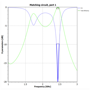
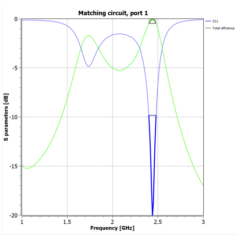
Figure Six – S11 Parameter

Example

As seen in the S parameter chart in figure 6, the S11 parameter extends just beyond -20-dB. The figure therefore suggests that at approximately -20-dB the antenna radiates at its maximum. At 0-dB the antenna radiates nothing. While this simulation may  look ideal, it is not practical for real world application. This is because the dark blue highlighted bandwidth (2.4-2.483-GHz) is difficult to realize in the physical world. In practical antenna circuits, the resonating frequency an antenna could transmit/receive is always met with some percentage of error, or acceptable deviation from nominal conditions. For example, the chip antenna we have chosen for the 3DoTX board has a frequency range from 2.4 to 2.5-GHz. A 100-MHz difference. By choosing more than the two components that have been shown below, more components can be added to open up the bandwidth of frequencies that can be received/transmitted by the antenna. Another great feature with Optenni is that you can tune the component values to see how each one effects the S11 parameter.

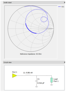
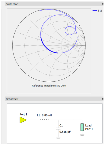
Figure Seven – Smith Chart (top) and matching generated circuit (bottom)

By looking at the smith chart in figure 7, we see that dark blue are highlighted on the graph corresponds with the dark blue area highlighted in figure 6. Recalling the information presented earlier about the smith chart and 50-Ohm impedances, we can see that the matching circuit accurately tunes the antenna to operate at the matched approximate 50-Ohm impedance.

In the matching circuit shown, the port corresponds with the input (i.e. the antenna) and the load corresponds with the SAMB11.

References

[1] Reference One

[2] Reference Two

[3] Reference Three

[4] Reference Four

[5] Fundamentals of Engineering Electromagnetics by David Cheng

[6] Reference Six

Acknowledgements

Thank you for Dr. Densmore, Dr. Rezvani, and Dr. Haggerty for help in contributing to understanding the matching network.

Gear Studies

Written by Railan Oviedo (Manufacturing)

Objective

For the Pete-Bot’s (P-Bot) method of movement, our project has implemented a
planetary gear system that incorporates the incline gear as the wheel and 3 planetary gears. The top planetary gear will be the driving gear that is connected to the GM6 motor, while the other two planetary gears will have ball bearings inserted into them—effectively making their presence their solely for the purpose of properly spacing the incline gear. In order to ensure the whole structure stays together, washers will be placed to prevent them from touching the chassis, and a triangular gear holder will be utilized to prevent the system from popping off the chassis.

Preliminary

For a planetary gear system to work, specific parameters must be made in order to ensure the gears can smoothly spin together. The equations to ensure this are as follows:

Equations (1) to (3) to determine the number of teeth for the gears and pitch diameter

“N” represents the number of teeth for the incline gear ring, the planetary gears, and the sun gear. As stated in the introduction, the sun gear will not actually be implemented, but it is still necessary for designing purposes. The variable “r” is for the ratio of revolutions between the sun gear and the incline gear.

The Pitch Diameter “PD” is the effective diameter of the gears, and it is determined by multiplying the number of teeth by the gear module “M.” The modules must be the same for all the gears in the system in order for them to operate smoothly.

Test 1

The initial “r” value chosen for the system was 3, so the sun gear would spin 3 times for every spin of the incline gear. The modules have been set to 1, so the number of teeth also determines the pitch diameter in millimeters. For the first trial, the incline gear was chosen to have 40 teeth – thus resulting in a 40 mm pitch diameter – with an outer diameter of 45 mm. From the equations, the other parameters were found as the following:

Equations (4) & (5) that show the number of teeth calculated

With this, SolidWorks was used in order to generate a simulation for the gears.

Image One – Initial Gear System

Because of the ball bearings, the lower planetary gears will have an increased inner diamater of 1/4 of an inch. This system was laser cut in order to rapid prototype with the P-Bot chassis.

Video Link

Image Two – Initial Wooden Gears

Gear Holder

The gear holder was made to fit the shape of the first gear system. The design is shown in the picture below:

Image Three – Gear Holder

The measurement numbers are given in centimeters. The 4 cm diameter circle represents the pitch diameter of the incline gear, and the 5 cm diameter circle reqpresents the total diameter of the wheel including the tire treads.

Test 2

After testing how the ring actually functions on the chassis, it was seen that the planetary gears for the ball bearings are incredibly flimsy. Furthermore, the wheel is not large enough to surpass the bottom of the chasis, as shown in the picture below:

Image Four – Rapid Prototype Implementation of Incline Gear

Due to this, a new system that utilizes a 42-teeth incline gear with “r” equal to 4 was used in order to increase the diameter of the wheel. From the equations, the other gears’ teeth were found as:

Equations (6) & (7) show the new number of teeth determined for the new gear system

Since the planetary gears will now have a wider pitch diameter, this should eliminate the issue of their stability for the ball bearings. Using this, another SolidWorks model was made, and these were also laser cut for rapid prototyping.

Image Five – Second Gear System

Image Six – Second Set of Wooden Gears

Results

After trying the alignment pattern of the gears for Test 2, it was found that the incline gear ring would not touch the driving planetary gear due to the fact that the incline gear becomes slightly raised when it is placed on the ground.

However, when attempting to use the 14 teeth gears in tandem with the alignment for Test 1 (Refer to Image 1), it was discovered that the gears were very close to being in the perfect spots for the whole system to function properly. Minor tweaks would need to be made on this alignment in order to get the positioning correct.

Test 3

The third and final test was to adjust the alignment from Image 1, and to then use the 14 teeth gears in place of the actual gears that should be used for it (i.e. 10 teeth planetary gears, and 20 teeth sun gear).

Image Seven – SolidWords Model for Test 3 (in mm.)

The original distance between a planetary gear and the sun gear was 15mm. This distance is reduced in the hopes of having the incline gear ring fit. To test whether this would work, the alignment pattern was cut out onto wood via a laser cutter.

Image Eight – Test 3 Alignment Cut-Out on Wood

The gear holder was also altered to fit this new alignment. The sides were made thinner so it is possible to see the gears behind it, and a slit was added to one side in order to indicate which side connected to the driving planetary gear. This side was also made slightly longer than the others in order to accommodate the fact that the incline gear slightly rises when it is on the ground.

Image Nine – Gear Holder for Test 3 (in mm.)

After laser cutting out the gear holder, the alignment pattern was tested and confirmed to work extremely well. Small washers were put in place between the wooden plate and the gears, and between the gears and the gear holder. These washers were small enough so that they only come into contact with the bearings inserted into the gears, thus resulting in a very small amount of friction when trying to spin the incline gear. The assembled pattern and a reference video are given below:

Image Ten – Test 3 Alignment Assembled with Gears

Video Link

D-Gear

Although the alignment was set, it now became necessary to change the driving planetary gear so that it fits the shape of the new GM6 motor shaft, which has a D-shaped profile. The model for this gear is given below:

Image Eleven – D-Gear

With the alignment set and the D-Gear created, it was then implemented onto the chassis itself, and can be seen as:

Image Twelve – Assembled Planetary Gear System

References

[1] Reference One

ModWheels 3DoT v 5.03 Integration and Test

By: Lucas Gutierrez (Project Manager) & Matt Shellhammer (Electronics & Control Engineer)

12/12/2017

As of Tuesday, December 12th, 2017, ModWheels does not have an operational v. 5.03 3DoT.  ModWheels was given a v. 5.03 on Monday, December 11th, 2017 without a Bluetooth module (HM-11) or a battery holder.  After soldering the HM-11 and battery holder, a test was done and motors and peripheral subsystems encoders could not be powered simultaneously.  Due to this, along with the HM-11 being inoperable, ModWheels decided to revert back to the SparkFun ProMicro microcontroller for continued prototyping until 3DoT issues have been resolved.

11/19/2017

To fulfill the customer’s request, ModWheels will incorporate the 3DoT as its choice for a micro-controller.  As of 11/15/2017, the most recent EE 400D class, the 3DoT v 5.03 was available for in-class testing.  When the 3DoT v 5.03 becomes available for long term usage, a more thorough blog post will cover its the testing and integration with respect to the ModWheels project.

ModWheels Custom Command and Telemetry

By: Lucas Gutierrez (Project Manager)


Discussion

An important aspect in fulfilling ModWheel’s mission requirements is integration with the Arxterra platform, both with the phone application and web based application.  To tailor and customize the user experience of the Arxterra applications to the ModWheels project, a few custom commands and telemetry will be incorporated. ModWheels would have implemented a 4 state custom command on the Arxterra GUI.  These states would have been RC (user controlled), Memory (Navigate with user), Replay (autonomous navigation), and Phase 2 (avoiding robots). RC mode would allow the user to control the ModWheels toy robot with the given slider options (motor). Memory would be a navigation of the maze with the user guiding the robot to the end of the maze. Replay would be the autonomous navigation of the maze based off Memory mode. Phase 2 would deal with avoiding robots in the maze. A new slider widget should be requested to allow for direct control of the servo on the ModWheel toy robot. The issues that arose revolving the 3DoT board made it difficult to test Arxterra on our toy robot.  Future teams that do decide to adopt this project should collaborate with Jeff Gomes when dealing with the Arxterra GUI.  Custom gadgets can be implemented that could make controlling the toy robot easier.

Custom Commands

RC Mode

Inside the maze

D-pad will be used to call predefined turn subroutines.

Outside of the maze

D-pad

Forward: Increase speed from current speed to 255.

Left: Move servo to left when pressed and move back to center when button is released.

Right: Move servo to right when pressed and move back to center when button is released.

Back: Decrease motor speed from current speed to 0.

Autonomous Mode

Make predefined turns based on recorded data.

Telemetry

  • Battery level indicator.
  • Robot orientation (when using web based application).
  • Direction (when using web based application).
  • Current room (when using web based application).

PeteBot Requirements

(Written by Elizabeth Nguyen (Project Manager) & Melwin Pakpahan (Missions, Systems, & Test)

Table of Contents

Objective

The requirements for the PeteBot (3DoT Chassis) are defined at two levels and provide the team with direction and to determine what shall be accomplished. Verification and validation are also outlined.

Current Status:

At this time, not all requirements have been confirmed and are pending approval. Some of the requirements listed below are different from the requirements listed in the PDD.

Level One Requirements

Program Requirements

  1. PeteBot shall be completed by Wednesday, December 13, 2017.
    1. This requirement coincides with the last day of class.
    2. This is the projected demonstration date for all toy robots.
  2. PeteBot shall cost no more than $200 as projected by the customer.
  3. PeteBot will be a toy robot.
    1. This requirement is defined through the customer expectations.

Project Requirements

  1. PeteBot shall use the PBX11 which is an alternative microcontroller to the 3DoT Board that utilizes the SAMB11 chip instead of the ATMega32U4 chip.
    1. In case the PBX11 board is inoperable, the 3DoT Board shall be used in its place.
  2. PeteBot shall navigate through a maze with remote control through the ArxRobot App or the Arxterra Control (based on Project and Mission Objectives).
  3. PeteBot shall be no larger than 4 x 3.5 x 3 inches.
    1. These measurements were taken at the widest dimensions of the chassis since it tapers at the bottom.
  4. PeteBot shall be able to memorize a path through the maze that is taught by the user (based on Project and Mission Objectives).
  5. PeteBot shall be able to autonomously travel down the path that was memorized (based on Project and Mission Objectives).
  6. PeteBot should be able to navigate the maze and avoid collisions when multiple robots are in the maze.
    1. The Rules of the Maze for the avoidance algorithm have been defined.
    2. Line following will be implemented if the motoer encoders are funtional.
  7. PeteBot shall have a chassis that is 3D printed.
    1. This is derived from a customer expectation.
  8. The total 3D print time of PeteBot’s chassis shall not exceed 2 hours (based on Project and Mission Objectives).
  9. The main body (chassis) of PeteBot shall be of one solid piece.
  10. PeteBot shall be assembled per the guidelines of Disassembly and Reassembly.
  11. The PeteBot Paper Shell shall resemble the CSULB mascot, Prospector Pete.
    1. This is a customer expectation.
  12. The PeteBot shall be able to perform all functions as programmed by the Arxterra app.
    1. This includes custom commands.

Level Two Requirements

System Requirements

  1. PeteBot shall operate for no less than 20 minutes using a fully charged battery.
  2. PeteBot shall attain an operating speed no slower than 3 centimeters per second.
    1. This speed is referenced from Mission Duration.
  3. PeteBot shall utilize the Generic Color Sensor Shield for line-following.
  4. The PBX11 board shall fulfill the requirement to be a custom PCB.

Subsystem Requirements

  1. PeteBot shall be powered by a RCR123A Lithium Polymer battery.
  2. PeteBot shall use a planetary gear system.
  3. The Generic Color Sensor Shield shall be located at the front of the PeteBot.
  4. PeteBot shall have a castor wheel under the Generic Color Sensor Shield to support the mobile phone.
  5. PeteBot shall utilize two GM6 brushed DC motors with an extended D-shaped shaft.
  6. PeteBot shall utilize two shaft encoders for line following.

Generic Color Sensor Requirements

Written by Charles Banuelos (Manufacturing and Design;Division Manager)

& Muhannad Al Mohamed (Electronic & Control Division Manager)

Worked on by Charles Banuelos (Manufacturing and Design;Division Manager) & Muhannad Al Mohamed (Electronic & Control Division Manager)


The Color Sensor Shield shall provide measurements from two color sensors with different I2C addresses.

The Color Sensor Shield shall be compatible with any Fall 2017 400D robot. (Specifically to avoid the caster wheel of PBot )

The Color Sensor Shield will use a generic 90 degree pin header to interface with the microcontroller.

The Color Sensor Shield shall use parts of 0603 (imperial) package size or larger.

The Color Sensor Shield will be compatible with any version 5.03 3Dot board.

The Color Sensor Shield will be 55 mm in length.

The distance from the outer edge of a color sensor IC to the other outer edge of the second IC will be 40.249 mm.

The White LEDs will be 2.76 mm away from each color sensor IC edge to edge.

The Color Sensor Shield will be 10.85 mm in width.

Generic Color Sensor Board Dimensions


Arxterra 3DoT Training Telerobotic Mode

Written by Nornubari Kanabolo MST DM and Muhannad Al Mohamed E&C DM

Table of Contents

Arxterra Client-Server “Community” Mode

Training for telerobotic mode included understanding how “Community Mode”works. This can seen by the diagram below

Community mode is communication between several parts of the Arxterra environment. This includes between the ArxRobot mobile app and Arxterra Control panel through a server and between the ArxRobot mobile app and ATmega32U4 microcontroller.

Choosing Community Mode

1. Click on Community Mode in the ArxRobot App. This is

2. Do not change any of these default settings

Creating Name for Project

In order to create a name for the project, type in your robot name as seen below. For example, for the Goliath project, you would put “Goliath” in the “Robot name” area. For “Pilot name or names” you would put your individual birth name such as “Nornu”.

Access the Arxterra Desktop Control Panel

To access the Arxterra Control Panel, go to arxterra.com and click on “Launch Now!” in the control icon.

Now you log in to the control panel using your Arxterra username(assuming you already registered for an account) and password for Arxterra.

Communication with your Project

Once in community mode and logged into the control panel you should be able to see your robot on the map. It is signified as a colored location marker. Click this and it will show the name of the robot and a “beam me up, Scottie!” icon. Click this icon to switch to Pilot mode.

 → 

Now you should be able to see what your phone camera sees. The interface created through the ArxRobot mobile app should be visible now as can be see below. To change the view of the camera through the app go to the settings>>phone configuration>>camera for streaming video.

Custom Commands and Telemetry

The process of creating Custom Commands & Telemetry in Community Mode is exactly similar to the process in creating them in RC Mode. It has the same 7 options the users can choose from (Boolean, Select, Byte, Unsigned Byte, Short, Unsigned Short, Header/Separator). However, Instead of only enabling the commands to show up in RC Mode the user would enable it to show on the Client Server Mode.

User Interface on the Control Panel

The user interface has 7 windows to show data:

  1. Lounge: shows the position of the project on a map
  2. Live Cast: If camera is enabled, it will show live broadcast from the phone that has the ArxRobot App.
  3. Telemetry: This window shows whatever commands were set for telemetry. Gauges and values of data packets would be shown in this window.
  4. Custom Controls: similar to the RC mode, this window shows the custom commands made by the user to interact with 3DoT Board.
  5. Controls: Also similar to the RC Mode, this window shows the D-pad that can be used to move motors of projects.
  6. Orientation: this window would show the position of the robot if the motion were enabled in the ArxRobot App.
  7. Messages: This window would show any emergency messages and notifications enabled by the user through custom commands. For example the user can have an alert message be sent and shown on this window if a Servomotor went to a specific position.

Telemetry

Telemetry is an automated communications process by which measurements and other data are collected at remote or inaccessible points and transmitted to receiving equipment for monitoring data.

The data packets sent from the 3DoT to the ArxRobot App can be displayed in the telemetry window by enabeling either Telemetry State or Telemetry Stream for custom Commands.

Predefined telemetry can also be shown in the window if enable in the Robot Capabilities Configuration.

Training on Arxterra 3DoT App RC Mode

Written By: Muhannad Al Mohamed (E&C DM)

Table of Contents

Objective

The Arxterra 3DoT App training had a goal of teaching E&C and MST members how to use their phones to communicate with their projects through Remote Control Mode. The ArxRobot Application has two different modes of communication with the Robot’s Microcontroller. The Remote Control Mode (covered in this training) and the Community mode (Covered in the next training session). The user, through the ArxRobot App, should be able to send commands to the microcontroller either through predefined commands or custom made ones.

Introduction

The communication in the RC mode is done wirelessly through Bluetooth with an easy pairing process at the initialization of the RC mode. Commands are sent to the microcontroller as packets that consist of bytes that have specific identifiers to indicates whether the command is a command or telemetry. The packets contain data bytes that can be processed by the pre-coded microcontroller.

User’s Interface

The user interface in the RC mode is user-friendly. The default setting shows the controls of two motors in a strip type command. The strip can be changed to a D-pad looking control. Custom commands can be set to show on the user’s interface when enabled.

During the training session, members were taught how to use the user interface to control motors by giving specific input, moving motors at the same time, and steering trim to maintain desired speeds.

ArxRobot App’s Settings

The commands used in the app can be changed in the settings of the app. To access the predefined and custom commands users needed to be in Developer Mode.

The Phone Configuration window in the setting enables the user to choose the way to connect to 3DoT board, show phone’s battery percentage on Control Panel, and flip Camera’s position.

The predefined commands are commands and telemetry functions defined by the Robot3DoTBoard and saved in the app as default commands to operate a Mar’s Rover. These commands, if needed, can be used by the user by enabling each command in the Robot Capabilities configuration.

The Custom Command & Telemetry Configuration window allows the user to create new commands to be sent the 3DoT Board and receive Telemetry from it.


Custom Commands & Telemetry

Options for commands and telemetry is created by adding an option and giving it a specific address from (0x40) to (0x5F). Each option should be chosen to be either for commands to be sent to the 3DoT or Telemetry to be sent by the 3DoT. Commands can be controlled by the ArxRobot App; however, not all telemetry options are shown on the app. Each option should be enabled to show in either RC mode or Community Mode.


There are 7 options the user can choose while creating a custom command:

1- Boolean:

This option enables the user to send a byte in the data packet to the 3DoT board with a value of either (0x00) or (0x01). In the user’s interface, it can be seen as a switch that can be changed. The user can choose a default value of either of the previous options. This option can be used to turn an LED on and off for example.

2- Select:

This option enables the user to have multiple outputs to switch to. It is similar to the Boolean switch; however, it can have as many options the user wants to switch into. It sends a 1 byte of data parameter with the packet that is sent to 3DoT board; however, the values sent can be modified by the user. The select option shows in the user’s interface as radio buttons.

3- Byte:

This option can be used to send a byte in the data packet but with a wide range that can be changed by the user. It has a default range from -127 to 128 where the user can control which value sent by moving a strip in the user’s interface. These values can be changed by the user in the Byte settings to the desired range but it would still be a byte range. The steps between each value can be modified as well. This option can be used to move a servo motor for example.

4- Unsigned Byte:

This option is similar to the Byte command. The only difference would be the default range that starts from 0 up to 255.

5- Short:

This option is also similar to the Byte/Unsigned Byte; however, this option sends two bytes in data packet. Because it sends two bytes, the short command has a wider range than Byte/Unsigned Byte. The default value of this options ranges from -32768 to 32767.

6- Unsigned Byte:

This option is similar to the short option; however, the default range for it goes from 0 to 65535.

7- Header/Separator:

This option does not send any data in packets sent to the 3DoT; however, it is used to make the interface more user-friendly. titles to commands can be given using this option and it can be used to as separator if it was used without writing anything to it.

Training document

Arxterra RC Mode training document can found at this link.

Optimizing RC Mode in Projects

Update: 12/5/2017

Room Showing Telemetry Command

By creating custom commands and telemetry, engineers can create commands that can enable them to control their projects through the maze. For example, the path taken by a robot can be sent back to the phone connected to the MCU using telemetry options to show which room the robot is in on the phone’s display using RC mode. By optimizing the translated code from EE346/EE444 written by Mark Huffman (Goliath Project Manager) and Matt Shellhammer (ModWheels E&C Engineer), the variable “room” value can be sent as telemetry to the ArxRobot app. In the ArxRobot app, a telemetry Select command should be created and called room where it shows the byte value on the phone.

Creating Telemetry command called Room

Selec command Room

Assigned options to show the room type as implemented from the maze

Room type is shown in RC mode interface

Phase Selecting Command

The same process can be implemented to apply choosing the phase each robot is taking. In her blog Mission Definition, Elizabeth Nguyen (Pete-Bot Project Manager) explained how there are four planned phases each project can take:

  • Phase 1: Record
  • Phase 2a: individual playback
  • phase 2b: 4 Robots, 1 maze
  • Phase 2c: Individual playback, predefined

This custom command can be applied by also creating a select command with the four options where the user can switch easily between phases.

Phase selection in RC Mode

Recording Phase

Whenever Phase 1: Record is selected, the robot should start saving its path in the EEPROM. The EEPROM library can be very useful to record data when the system shuts down, which is essential in keeping data. The process of saving the path the robot is taking is explained in Write to EEPROM blog written by Matt Shellhammer (ModWheels E&C Engineer).