Spring 2017 BiPed – Arxterra Control/Code

By: Jacob Cheney (Systems)

Approved By: Alexander Clavel (Project Manager)

Table of Contents

Introduction

During the final mission, where the BiPed will compete in the end of the semester game, it is required that our robot is controlled via Bluetooth. In order to accomplish this task, the BiPed will be equipped with a Bluetooth 4.0 transceiver that will receive commands from the Arxterra application on an iPhone. In this blog post I will be going over the design and test process that took place order to make wireless communication possible.

Custom Commands

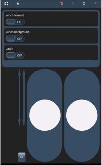
The Arxterra application is a robotics iPhone app that was specifically designed to control a robot over Bluetooth. It works by sending packets of data to the BiPed where it will then be decoded to control our system. To ensure our BiPed is receiving the correct data, we must first define our custom commands within the app itself.

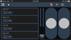
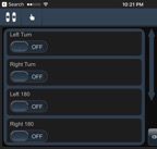
Figure 1: Arxterra Remote Control

Our BiPed utilizes 5 basic movements in order to navigate through a maze, they include walking, turning left 90 degrees, turning right 90 degrees, turning left 180 degrees and turning right 180 degrees. Because of this, we must create 5 custom commands to distinguish each function from another.

Within the app, each movement is assigned to a specific command ID. For our BiPed, the assignments are as follows:

Custom Command Command ID
Walk 0x01
Left Turn 0x41
Left 180 0x42
Right Turn 0x43
Right 180 0x44

Once the custom commands are defined, the app is ready to begin transmitting data. In order to actually do anything with these commands, we must now program the BiPed to decode the data packets.

BiPed Firmware

In this section I will go over the BiPed code and how it translates the incoming stream of data.

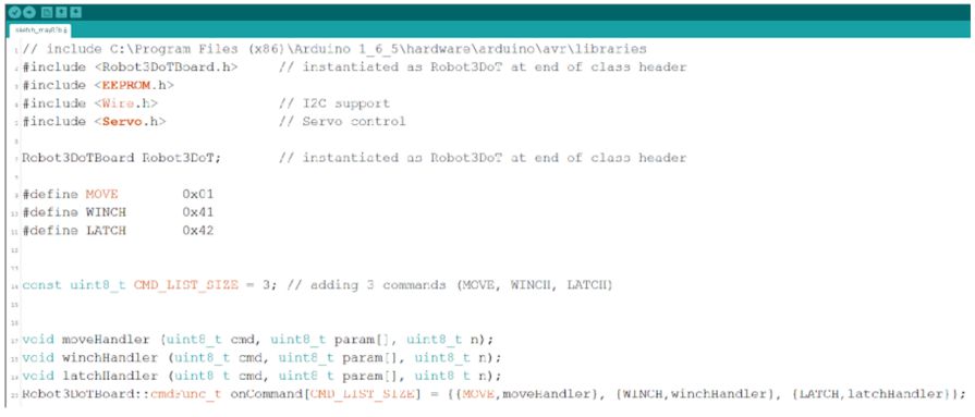
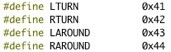
First we defined variables within the Arduino code that correspond to each command.

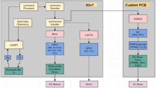
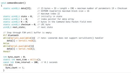
Next, within the CommandDecoder subroutine, every command packet the BiPed receives is broken down into individual bytes and read into an array called data.

Then the CommandHandler subroutine is called and assigns the variable cmd to equal the 2nd byte within the data array, this is where the command ID byte is found. Finally using if-else statements, the code is configured to call each movement subroutine based on the Command ID that was sent. This is shown below.

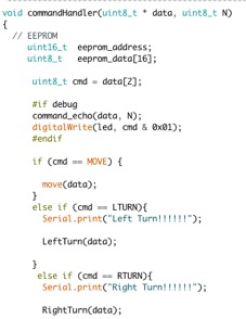
Looking at the code, you can see that I added Serial.print’s before every subroutine is called. This was used during the test phase to ensure the correct subroutine was being called when each command was sent.

Conclusion

After initializing all of the command variables and implementing a series of conditional if-else statements, the BiPed is now able to communicate wirelessly with the Arxterra app.

S17 Prosthetic Arm: Iteration of the Arm Design

This post is about the different problems faced during the design of the prosthetic arm and how they were overcome.

S17 Prosthetic Arm: Servo Rotation Accelerometer Test

This test is conducted to make sure that the wrist will work with the accelerometer in order to activate rotation only when it is in the correct position.

S17 Prosthetic Arm: Temperature Sensor Waveform Input Test

For this test, we are checking to make sure that we can record the temperature input as a waveform and use that information to employ the safety mechanism of powering down the PCB if any of the components get too hot.

S17 Prosthetic Arm: Sleep ISR Test with Analog Sensor

The Sleep ISR Test is done to make sure that once it sees a fluctuation in an analog signal, not unlike a temperature sensing heat breaching 50 degrees celcius, it will power down the MCU and the reduced current draw will cool down the PCB and all of her components.

S17 Prosthetic Arm: Finite State Machine Servo Test

The purpose of this test is to make sure our code can rotate the servo in the wrist of the prosthetic arm only when the EMG sensor detects muscle contraction.

S17 Prosthetic Arm: Buck Converter LTSPICE Simulation

To test if the buck converter we have designed is able to be used to step-down the voltage of the battery at 11.1V to the voltage needed to power the servos, at 5V, safely.

Spring 2017 SpiderBot – Custom PCB COMPLETED AND TESTED!!

Table of Contents

By Nicholas Jacobs – Project Manager

Introduction

The 3DOT controller is a minimalist board. It comes equipped with a two channel motor driver that drives SpiderBot’s two DC motors at 5 volts, leaving nothing to drive SpiderBot’s 3.3v winch motor. Our custom PCB incorporates an additional motor driver and PWM expander that enable I2C serial communication between the custom PCB and the 3DOT controller.

Requirement

SpiderBot shall incorporate a custom PCB. The PCB will consist of a PCA9685 PWM expander and TB6612FNG H-Bridge motor driver to drive a 6v Metal Gear dc winch motor at 3.3 volts.

Design Iterations

Despite shaving a lot of unnecessary weight off of SpiderBot, a problem still persisted. Operating the winch motor at 3.3 volts resulted in a 5 minute ascent time to the anchor point. After consulting with Shaun and Thomas, the E&C engineer and E&C division manager, I made the decision to run the winch motor at 5v which drastically improved the ascent time of SpiderBot. The only modification to the custom PCB was the addition of a 5 volt LDO.

When this design was presented to the customer, he rejected the idea of running the winch at 5v. He specified that there was no requirement in the Program Objective that prompted the need to run the winch motor at 5 volts- basically there is no need for SpiderBot to ascend fast. Hearing this, I pulled our PCB files in order to revert back to the winch being driven by 3.3 volts.

Once the design files were approved for fabrication, the Gerber files were created using the SparkFun CAM processor.  These files allowed for the PCB to be constructed,  allowed for the creation of the solder stencil, and solder paste from Osh Stencils. Osh Stencils has a very easy user interface to work with, the only gerber file that is need to create a stencil for your board is the .gtp file.

Bill of Material (BOM)

Eagle CAD has a ULP or User Language Program that will generate a complete list of materials used in either the schematic file or board file. Open Eagle CAD and the schematic of whatever BOM you want to create. In the taskbar enter BOM.ulp and press enter. If you get an error of some sort, just go to file -> Run ULP -> then select BOM. A window will pop up and under List Type select ‘parts’ and ‘file type’ select .csv, and save to well known location. This file type can be opened using Excel.

Open this .csv file from Excel, you may have to change the file type from ‘All Excel Files’ to ‘ All Files’ in order to see the .csv. When found double click to open. When this file loads it will look messy and Excel may ask you to save it as a different file type, maybe an .xls. To organize the data select the entire ‘A’ column and navigate to the Data tab, then under Data Tools click ‘Text to Columns’. When the window pops up make sure ‘Delimited’ is selected click next. Even though the file type is .CSV, which stands for ‘comma separated values’, in the delimiter section check the semicolon box. In the preview box below it, you’ll see the data begin to clean up. Click finish, and all your data should be organized.

Assembly and Soldering

Once the boards were received, plans were made to solder the components using a microwave oven, a solder stencil, and solder paste. The first step is to adhere the solder stencil over the PCB in such a way that only the SMD pads are exposed. This will allow for the solder paste to only be applied to the component pads.

Once the solder paste is applied, the components are very carefully placed in their respective spots on the PCB. Before placing in the oven, the oven was preheated to 300 degrees Fahrenheit. The board was then placed in the oven, allowing for a gradual temperature acclimation.   After about 90 seconds, the heat was increased to about 450 degrees Fahrenheit to melt the solder paste. Once the solder reflowed, the oven was turned off and the board was removed from the oven for cooling.


Testing

Code used to test PCB utilizes the Adafruit Motor Driver v2 library. Since the device communicates over I2C, the Wire.h library is also included.

The first step is to instantiate the motor shield object as seen on line 16. Since our PCA9685 IC has pin a5 pulled to Vcc, the address has been changed to 0x60.

After instantiating our motor shield object, we then need to tell the board which motor we are trying to drive, either motor 1 or 2. For testing, we have made two motor objects so that both motors can be tested.


Setup:

Start with Serial.begin(9600) so that we can output onto the serial console for debugging purposes.

AFMS.begin(); takes care of the I2C protocol such as Wire.begin, etc.

In order to be able to control the motor driver, the standby pin needs to be pulled high. This is done by using AFMS.setPin();

After, STBY has been enabled, we can now use the library to drive either motor by calling the object and speed function, and then calling the object and run function.

Example:

myMotor->setSpeed(255); //sets motor1 for full speed in our code.

myMotor->run(FORWARD); //tells motor 1 to run forward

Spring 2017 SpiderBot – Custom Commands Update

Table of Contents

By Jefferson Fuentes – MST

Requirements:

The Spring 2017 Spiderbot project, S-17 Spider, shall provide a live aerial video footage for end of semester game.  In addition, S-17 Spider, shall incorporate a grappling mechanism to elevate itself from the ground level.


Introduction:

The S-17 Spider features the ability to elevate itself off the ground through use of a grapple and winch system.  The purpose of this post is to provide an explanation of the Spring 2017 Spiderbot project, S-17 Spider, custom commands utilized in controlling project functions via the ArxRobot App.  The software block diagram (fig. 1) shows a layout of all functions used for control of project.

Figure 1 – Software Block Diagram


Commands:

The MOVE command is utilized to control the projects directional functions.  By sending individual commands to the two connected DC motors, each motor can spin clockwise or counterclockwise, allowing for desired direction.  

The LATCH command serves to control the single servo connected to 3DoT.  The servo is sent a signal to spin its full 180 degrees and release the grapple, hence the function name.

The WINCH command serves to control a single DC motor connected to the custom PCB via I2C.  Similar to the move command, a signal is sent to the DC motor to spin it clockwise or counterclockwise.   The motor serves to power a winch, which allows the project to elevate itself higher or lower.

The code for the custom commands is shown below.  The first step is initialization of the code (fig. 2), which includes all necessary files to run all functions denoted by #include <>.  The custom commands are then defined, #define, and given their address, 0xXX.  In S-17 Spider, we are using 3 custom commands which also needs to be declared in the following line.  The last few lines are the handlers.  Their purpose is to direct the incoming command to the appropriate function (custom command).  


Figure 2- Code Initialization


The parameter for all functions is 0 to 255, a byte.  This works wells with the MOVE command, which moves clockwise and counterclockwise.   The LATCH command controls the servo, which can only rotate 180 degrees.  To accommodate, 0-255 must be converted to 0-180.


ArxRobot Control:

The s-17 Spider uses the provided ArxRobot app for wireless control, via Bluetooth, of the project.  The three main function of the project are included (fig. 3) in the app layout.  For the S-17 Spider project all functions are in Boolean, meaning that either function is either on or off.  The winch function uses two Booleans to control the direction the motor spins.  The latch function controls the servo which turns the full 180 degrees one way or the other.  


Figure 3 – ArxRobot Layout


Spring 2017 SpiderBot – Cable Tree Design

By: Jefferson Fuentes

Requirements:

The Spring 2017 3DoT Spiderbot, S-17 Spider, is required to utilize the program assigned 3DoT board for processing and control.  In addition, S-17 Spider must utilize a custom PCB design for mission objectives.


Introduction:

S-17 Spider utilizes the program assigned 3DoT Board (Fig. 1), featuring an ATmega32U4 Microcontroller.  The 3DoT is prefabricated and designed to provide connections and control to two 5V DC motors, two 3.3V Servos, and an I2C port for expansion capabilities.  S-17 Spider will be using the two available motor connections, one servo connection, and the I2C pins for an external custom PCB.  The external PCB will be powered via 3.3V supplied by I2C and will be used to control a third DC motor.  The following will provide insight into S-17 Spider’s wiring layout, or “Cable Tree”.

S-17 Spider can be summed up in a system block diagram (fig. 3 & 4), demonstrating the projects functions and how connections are implemented.  From SBD, a total of 13 wires, 11 from 3DoT and 2 from PCB, will be used in the project.  Each of the three motors will incorporate a twisted pair technique to minimize noise and keep the keep wires traceable, connected to JST terminals.  The servo is hardwired and connected to JST terminals.  The I2C connection between the 3DoT and external PCB, consisting of 4 wires, will remain consistent in the color choice of the wiring to allow easier traceability, and will use.


Figure 1 – 3DOT board.


Figure 2 – System Block Diagram


Figure 3 – PCB System Block Diagram


Process:

“Cable Tree” planning first begins with a sketch (fig. 3), which follows the system block diagrams for the S-17 Spider project.  The sketch represents a rough draft of a propose cabling system to serve as a reference for a 3D rendering (fig. 4) as well as reference table for cable colors (table 1).  These are the building blocks for the final S-17 Spider Project build.


Figure 4 – Wiring Color Diagram


Figure 5 – Wiring Sketch


Figure 6 – SolidWorks 3D Rendering