Goliath Fall 2017 – Final Budget and Expenses

This post is in accordance with the project requirement L1.11, “Budget”. In comparison to both the total expected cost and actual cost column, we could see which resources were supplied, cut, or purchased.A good portion of the components was covered through the use of previous semesters’ components specifically the: motor, 3dot board, and battery. The […]

Goliath Fall 2017 – Goliath Arduino Code & Calibration

The purpose of this post is to link to the final Goliath code and explain the overall structure for future use. Secondly, to explain how the code needs to be updated and calibrated to a particular Goliath chassis. Overall, getting the Goliath code to work for this mission involved the creation of 16 files and over […]

Fall 2017: ModWheels Final Project Document

By: Lucas Gutierrez (Project Manager)

Table of Contents

Project Overview

Team

Fall 2017 ModWheels:

Project Manager: Lucas Gutierrez

Mission, Systems, & Test Engineer: Andrew Yi

Electronics & Control Engineer: Matt Shellhammer

Design & Manufacturing Engineer: Natalie Arevalo

Summary

The Fall 2017 ModWheels toy car is a new project within The Robot Company.  Its modular design comes from the changeable paper overlay, allowing the user to swap out to their preferred design.  To control the robot, a 3DoT micro-controller is used to connect the user to the robot via Arxterra, a platform for easy robotics integration.  A sensor suite will enable this to navigate a 2D maze, as defined by the customer. Infrared sensors gives ModWheels the feature of line  of the maze, keeping the toy car within the confines of the maze hallways. To avoid collision, a proximity sensor  gives ModWheels the ability to detect the other robots, which allow for the robot to avoid collision within the maze.  

Mission Objective for Fall 2017

ModWheels is a toy car that will navigate a multi-colored 2D maze using autonomous capabilities as well as Arxterra to guide the toy car through the maze. The initial phase consists of having the toy car navigate the maze with user input, to which ModWheels will then memorize the route taken during the initial phase and will be able to autonomously navigate the maze for the second phase, all while being able to detect other robots and avoid collision. These are the mission objectives stated by the customer.

System Design

ModWheels is sized to fit the maze as defined by the customer for the Fall 2017 EE 400D semester.  This final document will detail the mechanical design, electronics and control, and sensor suite that made ModWheels the project that it is.

Figure 1: Fall 2017 ModWheels Prototype Used for Final Mission

Subsystem Design

Modeling Results

The use of SolidWorks helped to the ModWheels project design and model the chassis, steering mechanisms, and holders implemented onto the toy car.  Tire treads were designed, modeled, and provided by Jeff Gomes.

Figure 2: Fall 2017 ModWheels 3D Model

Interface Definition

To help satisfy customer requirements, a system block diagram defines the capabilities of the ModWheels electronics and control.  The interface matrix also verifies that the system block diagram and actual implementation of the ModWheels go hand in hand.

Figure 3: Fall 2017 ModWheels System Block Diagram for 3DoT v. 5.03

Figure 4: Fall 2017 ModWheels System Block Diagram for Pro Micro

Figure 5: Fall 2017 ModWheels Interface Matrix

Mission Command and Control

An important aspect in fulfilling ModWheel’s mission requirements is integration with the Arxterra platform, both with the phone application and web based application.  To tailor and customize the user experience of the Arxterra applications to the ModWheels project, a few custom commands and telemetry will be incorporated. ModWheels would have implemented a 4 state custom command on the Arxterra GUI.

Electronics Design

In the design phase, ModWheels was design to electronically and mechanically adapt to the v. 5.03 3DoT, which was to be provided by the EE 400D .  Due to complications with the fabricated 3DoT v5.03 and the limited amount of time we were required to resort to the use of the Sparkfun pro micro and motor driver for the final implementation.

Figure 6: ModWheels Cable Diagram for Pro Micro (Used on mission)

Firmware

The software is one of the most important factors within the ModWheels project for maze navigation.  With the help of Matt Shellhammer (Electronics & Control Engineer for ModWheels), an adaptation for maze navigation from EE 444 to EE 400D was made.  Since the 3DoT was not used on the mission due to complications, a more simplified code was implemented on the prototyping board.

PCB Schematic & Layout

Among the requirements set by the customer, all projects must design and fabricate a custom PCB. However, due to the nature of our project and its design, a custom PCB is not necessary. In order to get the requirement of the custom PCB waived, a cable diagram for our project was provided. The description and diagram show that the components within our design can be directly connected into the 3Dot board without being interfaced through a custom PCB.

Figure 7: ModWheels Cable Diagram for v. 5.03 3DoT

Hardware Design

The ModWheels toy robot implements a blend between 3D printed components, as well as laser cut wood.  This blend of materials helps to optimize cost and time (wood being inexpensive and quickly cut by a laser cutter) while keeping functionality (3D printed steering mechanism and engine block to hold the servo).

Figure 8: ModWheels Fall 2017 Prototype used on mission

Verification & Validation Test Overview/Summary

To confirm implementation of requirements, verification and validation of  requirements of the ModWheels project was performed.  To perform verification and validation of the requirements, a verification list and a validation test procedure was created.

Power Allocation

As requested from the customer, the ModWheels will be implementing the 3DoT micro-controller.  Due to the nature of the 3DoT, power restrictions must be made to ensure proper operation and performance. The power budget not only gives a worst case scenario of power consumption, but also helps to provide numbers to calculate mission duration, a very important factor to mission success.

3D Print Times

As set by the customer, there is a limit on the time allotted for the parts that will be 3D printed for the robots. The rule for 3D printing is that total print time must not exceed six hours, with no single part taking more than two hours to print. Once the 3D models were finalized and sent to be printed, a full rundown of labor, time, and cost were provided, which gives ModWheels final print time results.

Figure 9: Final print time summary

Cost Report

As part of the requirements stated by the customer, a budget was set for the ModWheels project for no more than $200.00 .  To help cut some costs, the EE 400D previous semester’s inventory of electronics, hardware, and materials were provided for use.  The Budget report includes total cost of the project as well as cost of the project offset by inventory.

Figure 10: Fall 2017 ModWheels Budget

Schedule

To help keep ModWheels on schedule, a project plan was created. The project planning along with the project burndown helps to give an estimation to work performed and work needed to complete the project.

Figure 11: Fall 2017 ModWheels Top Level Schedule

Figure 12: Fall 2017 ModWheels Project Burndown


Future Work

As the Fall 2017 semester concludes, a list of tasks have been compiled for following semesters to help further the ModWheels project and improve the 400D class.

  1. Fix IR shield to get improved readings and improve line following (change resistor values and refabricate as well as narrowing the distance between inside IR sensors to improve line following).
  2. Implement 3DoT v5.03 within ModWheels.
  3. Improved Steering
    1. Improve steering mechanism on ModWheels chassis to improve steadiness of steering.
    2. Change screws holding steering mechanism together to clamps or something that locks together so they steering mechanism won’t unscrew as it moves and turns (similar to what holds the 3DoT into place on the ModWheels chassis).
    3. Reduce size of servo holder to have a tight fit for the servo so it won’t move as it tries to move the steering mechanism.
  4. Improve software to implement Arxterra control of the robot (implement and test software developed for 3DoT v5.03 ModWheels after v5.03 is fixed).
  5. Improve power budget (more testing with servo to determine current draw and effectiveness at different supply voltages).
  6. Design modifications to allow for software upload while 3DoT is in the ModWheels chassis.

Fall 2017: ModWheels Schedule

By: Lucas Gutierrez (Project Manager)

Discussion

To help keep ModWheels on schedule, a project plan was created. The project planning along with the project burndown helps to give an estimation to work performed and work needed to complete the project.

Schedule

Figure 1: Fall 2017 ModWheels Schedule

Figure 2: Fall 2017 ModWheels Planning

Figure 3: Fall 2017 ModWheels Design (1 of 2)

Figure 4: Fall 2017 ModWheels Design (2 of 2)

Figure 5: Fall 2017 ModWheels Assembly

Figure 6: Fall 2017 ModWheels Launch

Figure 7: Fall 2017 ModWheels Project Burndown

Fall 2017: Interface Definitions

By: Andrew Yi (Mission, System, & Test Engineer) & Matt Shellhammer (Electronics & Control Engineer)

Approved by: Lucas Gutierrez (Project Manager)

Discussion

An important factor to operating the ModWheels project is linked to the connectivity of the micro controller and the sensor suite on the ModWheels chassis.

System Block Diagram

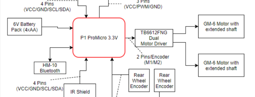
Due to unforeseen circumstances outside of our control, ModWheels was unable to implement a v. 5.03 3DoT micro controller.  Instead, the board used for prototyping was used, the SparkFun Pro Micro.  The ProMicro microcontroller replaced the 3DoT, but uses the same chip (ATMEGA 32u4).  3DoT implementation should be simple because of the similarities of the 2 microcontrollers. The encoders are connected via analog, sending data to the microcontroller, which then transmits data to the motor driver.  1.5V AA batteries power the toy robot via breadboard connections.

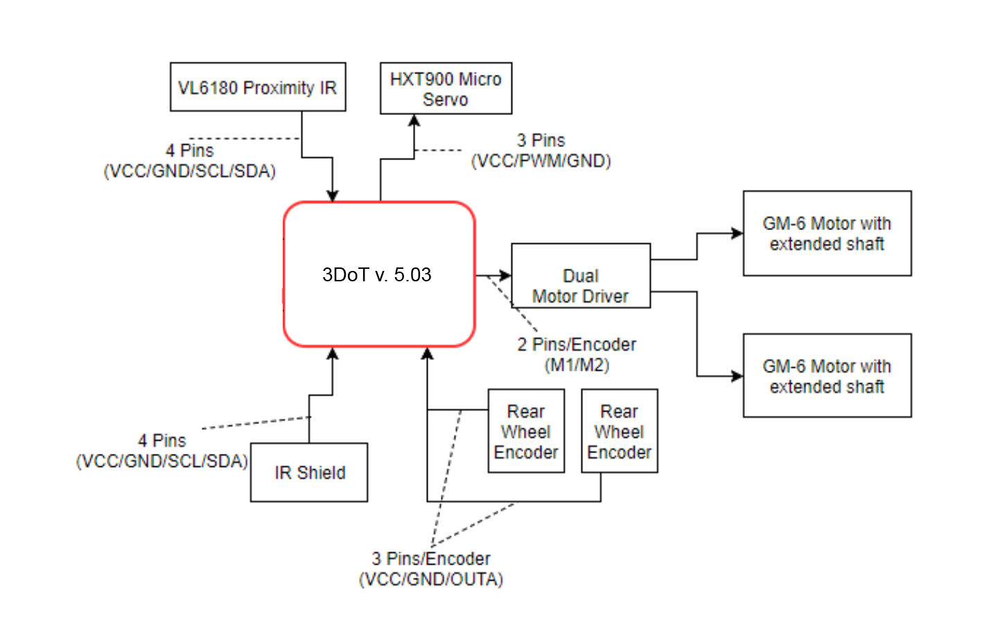
Figure 1: 3DoT v. 5.03 System Block Diagram

Figure 2: Pro Micro System Block Diagram
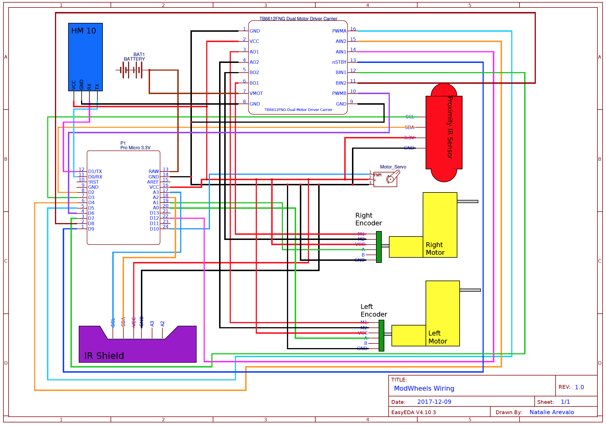
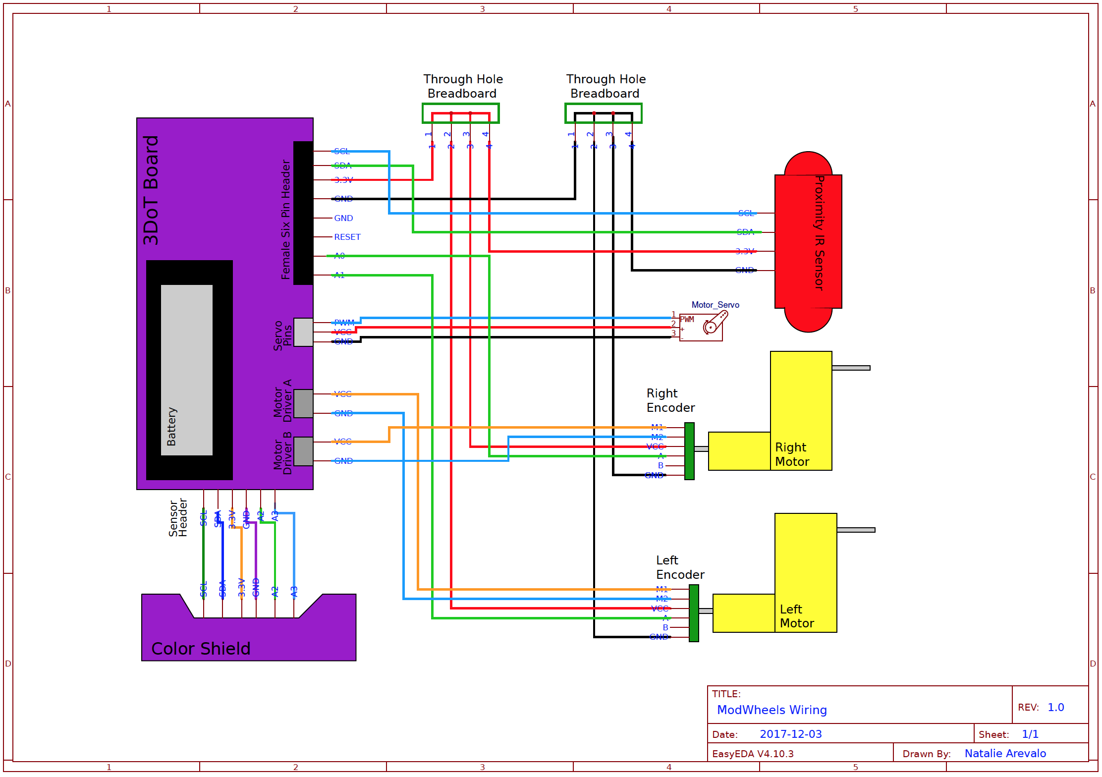
Interface Matrix

In this interface matrix we show how all peripheral electrical components will be connected to the 3DoT v5.03. ModWheels has a total of six peripheral devices, these devices are a micro servo, two magnetic encoders, two extended shaft GM6 motors, and a IR proximity sensor. These were all to be connected to the 3DoT without a PCB, however instead we were going to use a through hole breadboard to solder headers onto and create more Vcc and GND connections. With this in mind no PCB was required and all peripheral devices have a connection to the 3DoT with extra space for two more analog inputs. Only one channel of the quadrature magnetic encoders were used since the resolution was fine enough to make turns however if there was ever a need to include the second channel for the encoders there is still the remaining two analog connections on the sensor header.

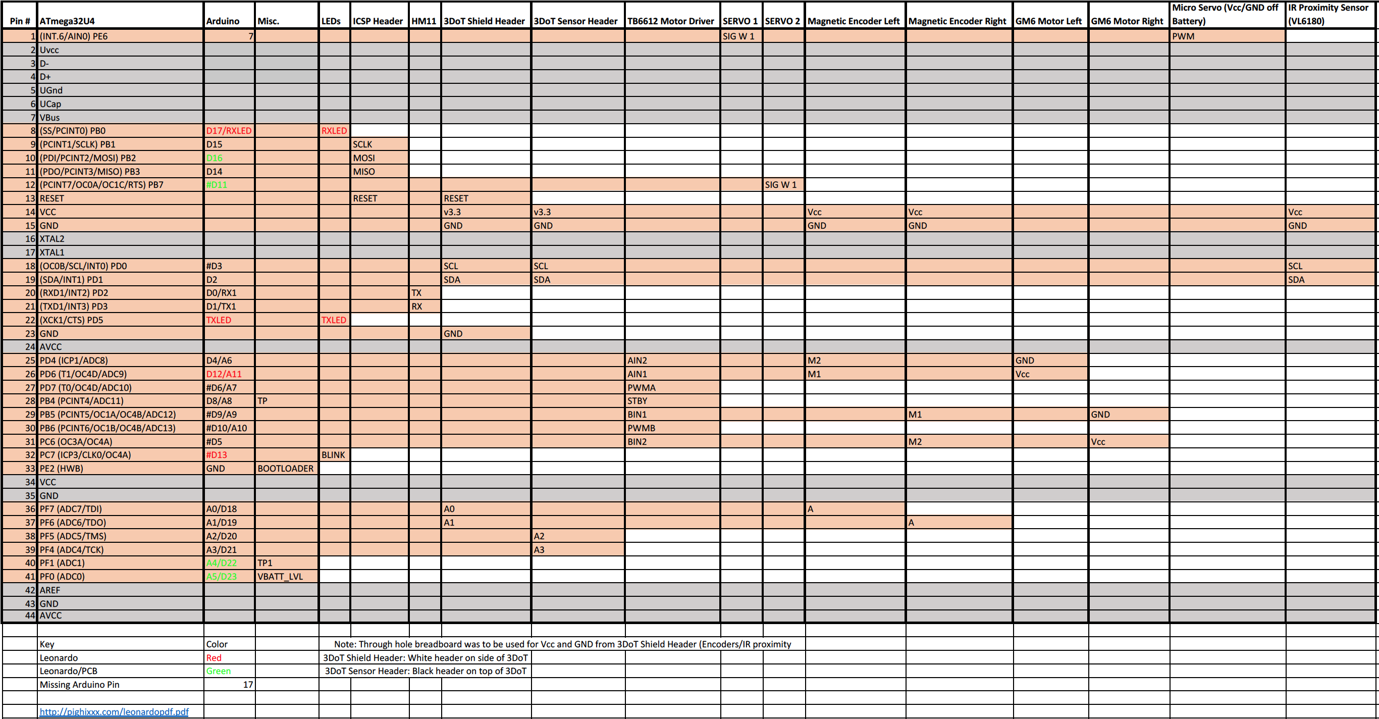
Figure 3: Interface Matrix

Fall 2017: ModWheels Verification & Validation

By: Andrew Yi (Mission, Systems, & Test Engineer)

Approved by: Lucas Gutierrez (Project Manager)

Introduction

To confirm implementation of requirements, verification and validation of  requirements of the ModWheels must be performed.  To perform verification and validation of the requirements, a verification list and a validation test procedure was created.

Verification & Validation

ModWheels Verification & Validation Plan

Verification & Validation: List & Test Procedures

ModWheels Verification & Validation: List & Test Procedures


Fall 2017: ModWheels Electronics Design

By: Matt Shellhammer (Electronics & Control Engineer)

Approved by: Lucas Gutierrez (Project Manager)

Discussion

Due to complications with the fabricated 3DoT v5.03 and the limited amount of time we were required to resort to the use of the Sparkfun pro micro and motor driver for the final implementation. The IR sensor shield was used in our design to preform line following throughout the maze to keep the car within the maze and on a straight path. The IR sensor shield was also used to detect intersections so ModWheels could monitor its location within the maze and travel the correct path (either predefined or defined with Arxterra). The servo was used in the front of our chassis within a custom built servo holder to steer the ModWheels car. It was used with a steering mechanism that was based on the Sandblaster 3D sand buggy front wheel steering mechanism. The turns were then implemented using the micro servo as well as the two GM6 motors and two magnetic Hall Effect encoders to perform electronic differential steering and electronic differential turning.

Electronic Design

Electronic Devices Used

  1. Substitute for 3DoT v5.03
    1. Sparkfun Pro Micro (3.3V/8MHz – 32U4)
    2. Sparkfun Motor Driver (TB6612FNG)
  2. IR sensor shield (designed by Charles & Muhannad)
  3. Micro Servo
  4. Two Extended Shaft GM6 Gear motors
  5. Two Magnetic Hall Effect Encoders

Figure: Wiring Diagram

Fall 2017: ModWheels Hardware Design

By: Natalie Arevalo (Design & Manufacturing Engineer)

Approved By: Lucas Gutierrez (Project Manager)

Discussion

Various modifications were done to the original chassis to be able to complete the mission proposed the customer. Major modifications were done to the wooden chassis to make it compatible with the 5.03 3DoT board. Openings on the top part of the chassis were made so that all of the ports and headers could be accessed. In addition, another opening was made to be able to place the battery into the 3DoT board. Furthermore, an opening in between the GM6 motor placing was made to have the wires of the motors and their encoders be brought up and over the top part of the chassis to plug into the board. Another piece was cut out of the top part of the chassis to allow for the servo to be able to be raised and lowered as it was connected to the front axle. Additionally, six 3mm holes were strategically placed in which dawls would be later glued into. Three of these holes and the respective dawls were set aside for an anchoring point for the servo holder. The other three holes and their dawls were used to hold up 1.5×1.5 in platform to become a phone holder. Two more 5mm holes were also placed in the back to become zip tie holders to keep wires secured. Finally, openings were made for the motor encoders adjacent to the existing openings for the motors

The bottom part of the chassis also had several modifications done to it as well. Matching opening were made adjacent to the existing openings for the motors as it was done with the top part. Openings were also made for the Bluetooth module on the bottom of the 3DoT board and for the header for the IR/color shield. Two 5mm holes were made in the middle of the part place a zip tie that would be used to secure the wires from the IR/color shield. In addition to these holes, two 3mm holes were made in the front of the part for the placement of the front axle. Finally, on both the top and the bottom parts of the chassis, 3mm holes were made along the sides of the chassis to replace the wooden tabs with plastic spacers with screws and nuts to keep the two pieces separated.

Now, several parts were also molded and 3D printed as part of the hardware design. More specifically, the front axle and the servo holder were designed and 3D printed. The front axle was modeled after the axle of the sand buggy and was scaled down to fit our design. The front rack of this axle had tabs added to it as place to where the proximity sensor would be attached. The other parts that make up the attachment point for the wheel and then to the front rack were super glued to be over a little more than 90 degrees. The front axle was assembled together using screws and nuts and the proximity sensor was attached in the same way. To continue, the servo holder was designed to look like an engine block. The design included hollow motor heads as well as a hollow block that allowed the servo to be placed inside and then raised or lowered as needed to be attached to the front axle. On the right side of the of the servo holder, tabs were also added to hold the wires of the proximity sensor out of the way.

Some final modifications that were done in the hardware design involve the wheels and the mounting of the IR/color shield. The wheels in the front had plastic sleeve placed through their point of attachment where a screw was slid thought and then screwed into the front axle. The back wheels’ points of attachment were changed from a round circle into a ‘D’ shape to press fit into the ‘D’ shaped axle of the dual shaft motors. As for the mounting of the IR/color shield was made with a piece of female header and ribbon cable. The piece of the female header and the ribbon cable were hot glued together. This unit was then hot glued to the bottom of the chassis so that when the IR/color shield would be connected it would be as far forward as possible.