
Fall 2016 Velociraptor (W): Final Project Document
By Lam Nguyen (Project Manager)
Table of Contents
Executive Summary of Project
Project Objectives
For CSULB Fall 2016 semester, the Velociraptor biped robot project will branch off to a new species of dinosaurs and set up a new baseline with the Theo Jansen robot design. The Velociraptor is to be a toy robot resembling a Theropodous dinosuar suborder by it’s static walking movement. The objective of this project focuses on utilizing a Theo Jansen design to produce a walking robot that will be remotely controlled through Bluetooth communication by using the Arxterra Control Panel. The robot’s application will have a 3DoT MCU board and demonstrate it’s feasibility by participating in a game with other robots.
Mission Profile
The Mission Profile of the Fall 16 Velociraptor is to participate in the game arena called Save the Robot on the last day of school, December 14th 2016 at 9:00 am. The game will involve Velociraptor chasing other toy robots through various terrains tele-robotically from the Arxterra control panel. The robot’s application of the 3DoT board MCU will demonstrate it’s walking capabilities by navigating through terrains in a game.
Project Features
DC motors
Apart from previous semester the Velociraptor’s project design had problems with servos that actuates a walking motion. DC motors were introduced to have a continuous rotation for our walking motion.
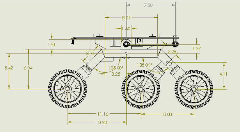
3D Model – Theo Jansen Biped Robot Model
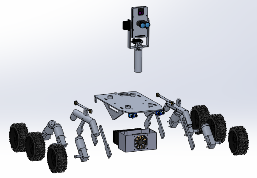
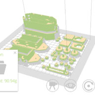
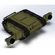
In order to design the robot with the Theo Jansen model as the project baseline. The project used Solidworks 3D modeling to validate and verify new designs within a short period of time. Using unique applications from Solidworks the mass properties helped save time and money on both printing the parts.

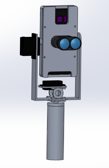
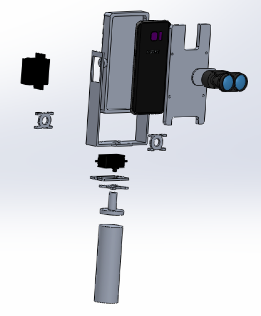
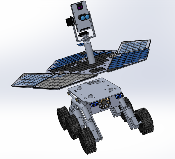
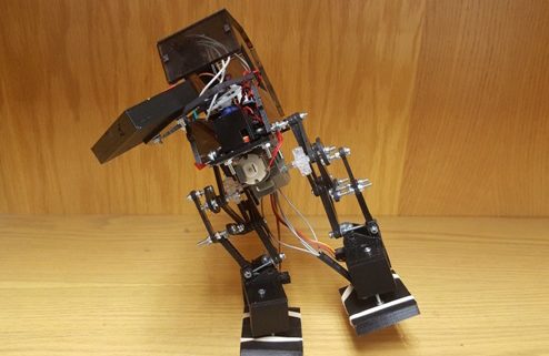
Picture 1. Theo Jansen BiPed Robot Model
Rotary Sensor and A/D Converter
With the new actuators for the walking motion. DC motors has less precision for every full rotation, therefore by using rotary sensors and A/D converter we will be able to track each leg’s position for a stepping motion.
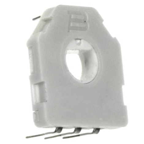
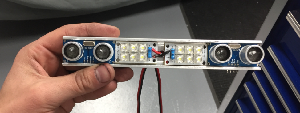
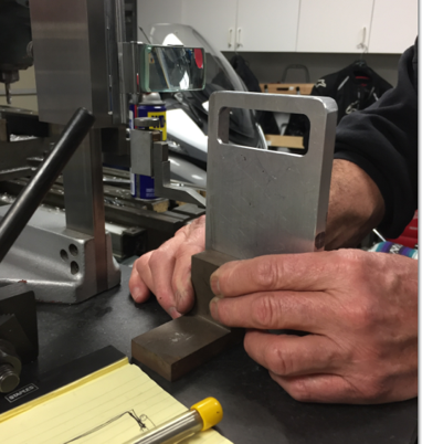
Picture 2. Rotary Sensor
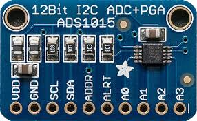
Picture 3. A/D Converter
Experiment List/CheckList
For the Final Verification and Validation Test Plan the project was given a checklist that stated the project’s requirements and experiments to figure out the results.
velociraptor-experiment-listchecklist
System Design
System Block Diagram
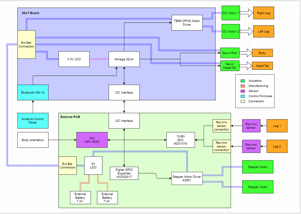
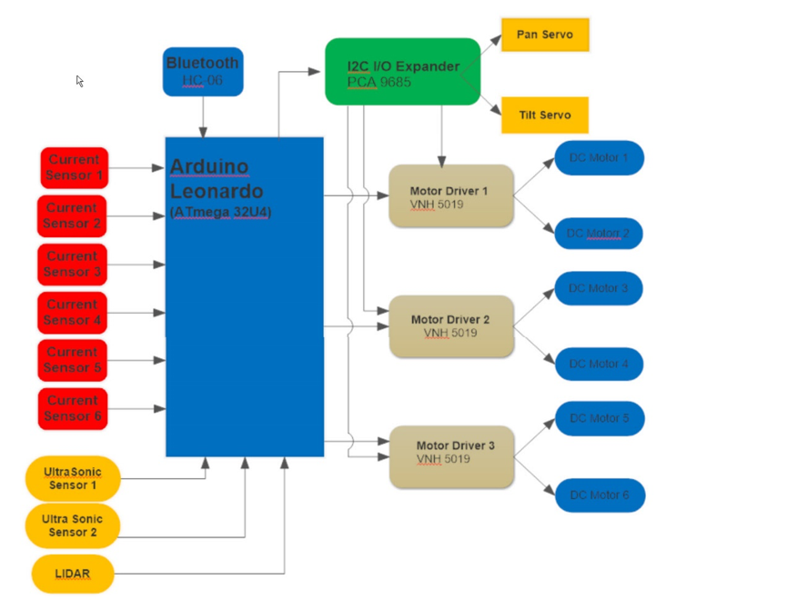
Figure 4: System block diagram Velociraptor (W)
The system block diagram for the velociraptor group was designed in order to use an external PCB that would be able to interact with the 3dot board embedded system. The system block diagram displays the overall connections that are needed to make the controls of the velociraptor possible. For the velociraptor PCB, it will have stepper motor drivers (A3901) which will have 2 stepper motors which control the linear actuators. With the help of the actuators we will be able to change the pattern of the step. For instance if the velociraptor needs to go up an incline, it would be able to step higher and not hit its foot against the bottom of the incline. In order to have the stepper motor driver be compatible with the I2C interface, we will utilize a GPIO expander that is I2C compatible. The driver will control the linear actuators. The linear actuators will change the radius of the rotational movement which will change the motion of the leg movement. For more information on each block of the diagram, readers are advised to visit the blog post link cited below.
Subsystem Design
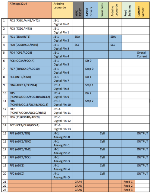
Interface Definitions
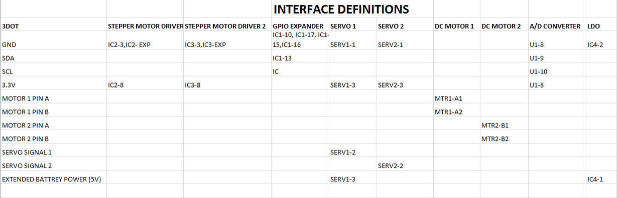
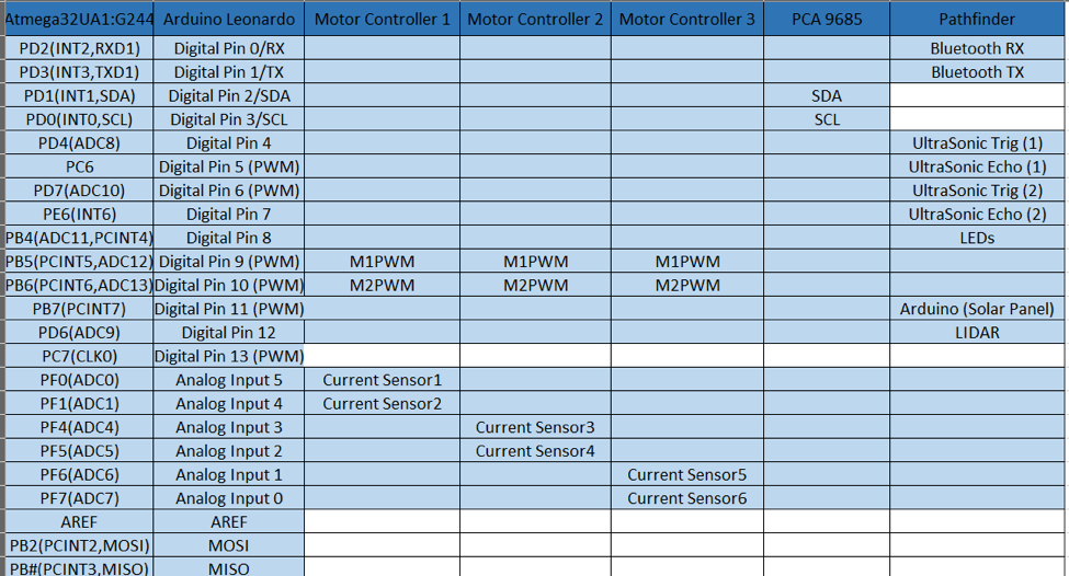
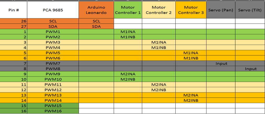
Figure 5. Interface Definition
The above figure is for the interface definition which is linked to the cabling tree diagram. Both of the above figures are linked in the sense that the interface definition is an outlined pin layout from the EagleCAD schematic while the cabling tree demonstrates what the layout will look like. The EagleCAD schematic was designed by the electronics engineer and through that the manufacturing engineer is able to know how to design the PCB and have the right connections.
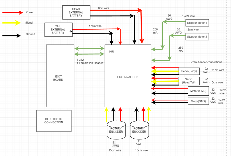
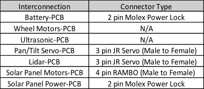
Figure 6. Cable Tree
In the cable tree diagram, there is more details regarding the connection types; the wire lengths and also the gauge sizes. The cable tree diagram that has been provided below is based on the system block diagram and follows the same format and layout.
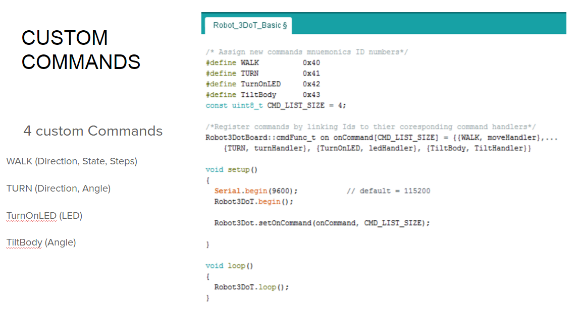
Mission Command and Control
The command and control of the velociraptor was to be designed in such a way that both the systems and electronics engineer have a good understanding of the 3DoT library provided by Professor Hill. The library needed to be modified in order to be able to include the custom command for each senior design group. For procedures on how to create custom commands and how to create a custom telemetry commands on the Arxtera control panel, readers should visit the systems blog post on how to create custom commands as well as telemetry commands. For the telemetry we will be displaying the roll, pitch and the left right rotary sensor values. A rotary encoder will be able to tell us how much in each direction the encoder has been turned. The custom command is when we have information that is being sent to the robot from the user. The custom command that we created for static walking for instance; it lets the velociraptor know when to start walking. However, telemetry would be the robot sending back information to the user what the leg placement is. There are two separate blog posts on custom commands and telemetry commands. Both of these blogs can be reviewed in order to gain a better understanding of the commands.
Electronic Design
Rotary Sensor
The rotary encoder is necessary to know the position of the dc motors. Without them, the walking motion would be a disaster. They are potentiometers. The signal is converted to a digital, and it is read via I2C.
Control Algorithm Code
The C++ code is a control algorithm for the velociraptor. It moves the servo which moves the head and tail to control the center of mass. It uses DC motors and rotary encoders to control the legs properly. Overall, it controls its walking motion and its turning.
Firmware
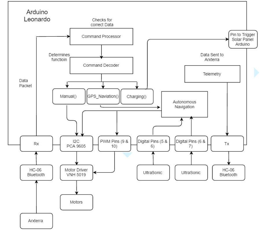
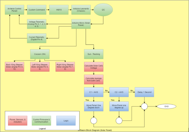
Software Block Diagram
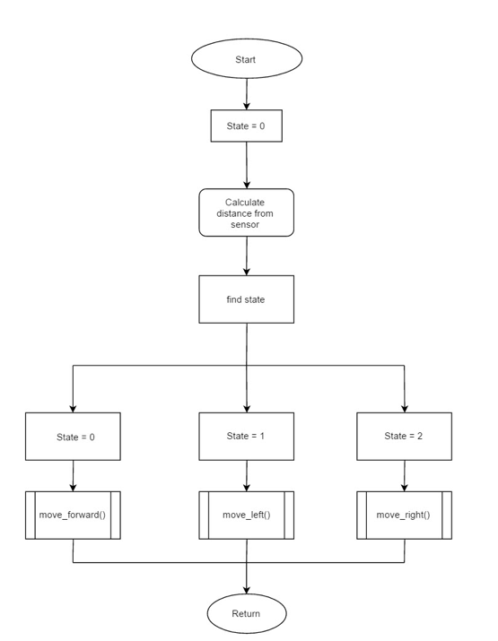
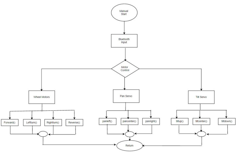
The software block diagram shows a detailed description of what coding blocks information were needed to implement the move commands for the velociraptor. For instance, dynamic walking was a walking style in which the customer would have liked to accomplish but unfortunately wasn’t successful. For the static walking motor commands, the velociraptor was programmed to be able move forward, move backwards, turn right and turn left. The turn commands go into details about describing how a turn occurs after the foot has been planted in a stable position while the other foot is continuously being moved until the robot is able to turn in the specified direction. Identifying the necessary components and flow chart diagrams of what the velociraptor motor commands were supposed to do, made the coding a little bit easier when it was time to implement it in Arduino.
Sample of Code:
Link: telemetry-and-custom-command-sample-arduino-code-1
PCB Schematic
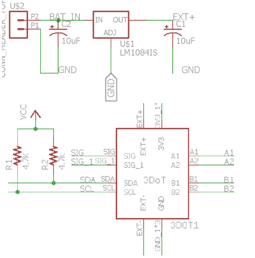
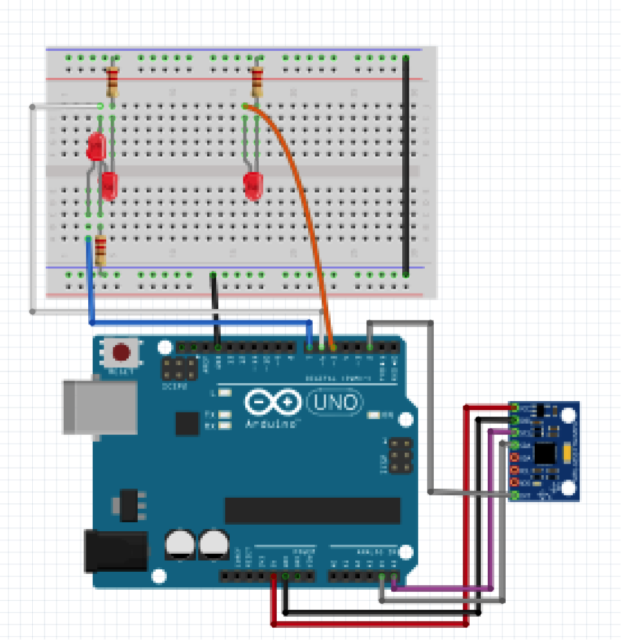
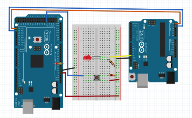
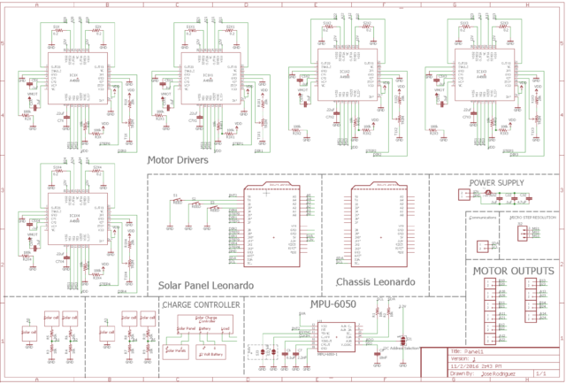
Fritzing Diagram/EagleCAD Schematic
The Fritzing diagram and Eagle schematic lays out how the components connect together on the PCB. Fritzing gives you a more visual representation while Eagle shows all the details of the connections. Once the Eagle schematic is complete, the manufacturing engineer fabricates the board so that it can be coded.
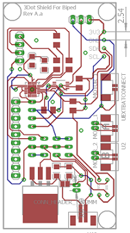
PCB Layout
The PCB layout was carried out through EagleCAD. The design utilized thru-hole components and L-shaped form to integrate with the 3DotBoard. Majority of the IC components were placed on the top layer to utilize a SMT solder paste stencil for reflow soldering. Only one IC component was placed on the bottom layer, which will be soldered through hand soldering. The picture below shows the PCB layout for the custom PCB of the Velociraptor. Decoupling capacitors were placed close to the IC components and wire sizes were adjusted to prevent problems with the power and signal lines. For PCB fabrication, OSH Park was chosen.
For more information, the blog post below will give detailed information regarding the PCB layout.
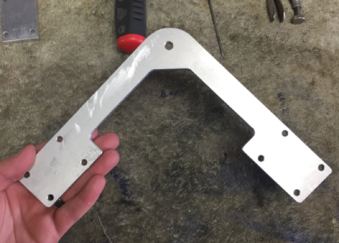
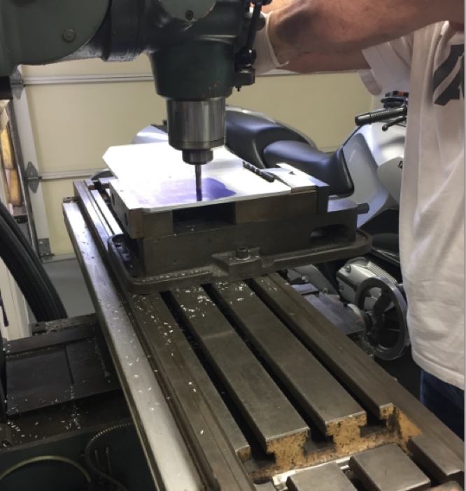
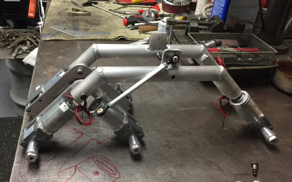
Hardware Design
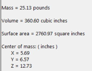
To fulfill requirements, a modified version of the Theo Jansen linkage was integrated with the leg design. The continuous rotation of the linkage corresponded with the continuous motion of a DC motor. The design was created in SolidWorks to observe features such as center of mass. The center of mass was accurately calculated from a custom library of densities in SolidWorks. Subsystem components, such as the toe joint and see-saw body, were to fulfill requirements and improve the design from previous generations of the Velociraptor.
For more information, the blogpost below will give thorough information regarding the hardware design.
Verification and Validation Test
The verification and validation matrix is a complied version of the requirements that the velociraptor group was required meet. In this matrix below, we notice that the requirements have been labeled as either a shall, should or will. For this Wednesday velociraptor group, we were able to accomplish about half of the will requirements that were expected from us. In the figure below, readers can find a copy of the verification and validation report. Matrix has been provided below in order to give viewers a better understanding of project requirements.
Project Status
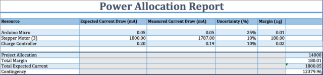
Power Allocation
For the power allocation report, the velociraptor robot consumes a total of 375mA when in complete motion. Based on a torque test performed by the electronics engineer in our group, we were able to determine that the DC motors can move a mass that is at a 1000g maximum. Due to robot size being 348g, we know that the motors will be able to successfully control the robot without stalling.
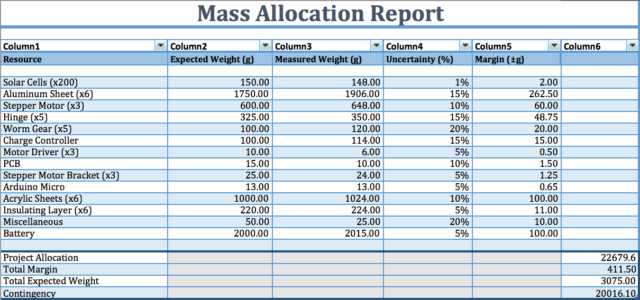
Mass Allocation
The overall weight of the velociraptor is 348g which is only using 34.8% of our maximum requirement of having it not weigh more than 350g. This therefore fulfills our requirement of the total mass and also makes it possible to have the GM9 motors supply enough torque to move the velociraptor. The final mass report which is provided in the figure will be able to provide more information about the overall weight distribution of other components.
Cost Report
The cost budget was finalized by the customer to allocate the cost to each project. In the end the customer was the deciding factor for the Velociraptor (W) budget. In the cost report the items were provided by the customer were $0.00 and this help the project lower the budget to $46.55.
Product Breakdown Structure
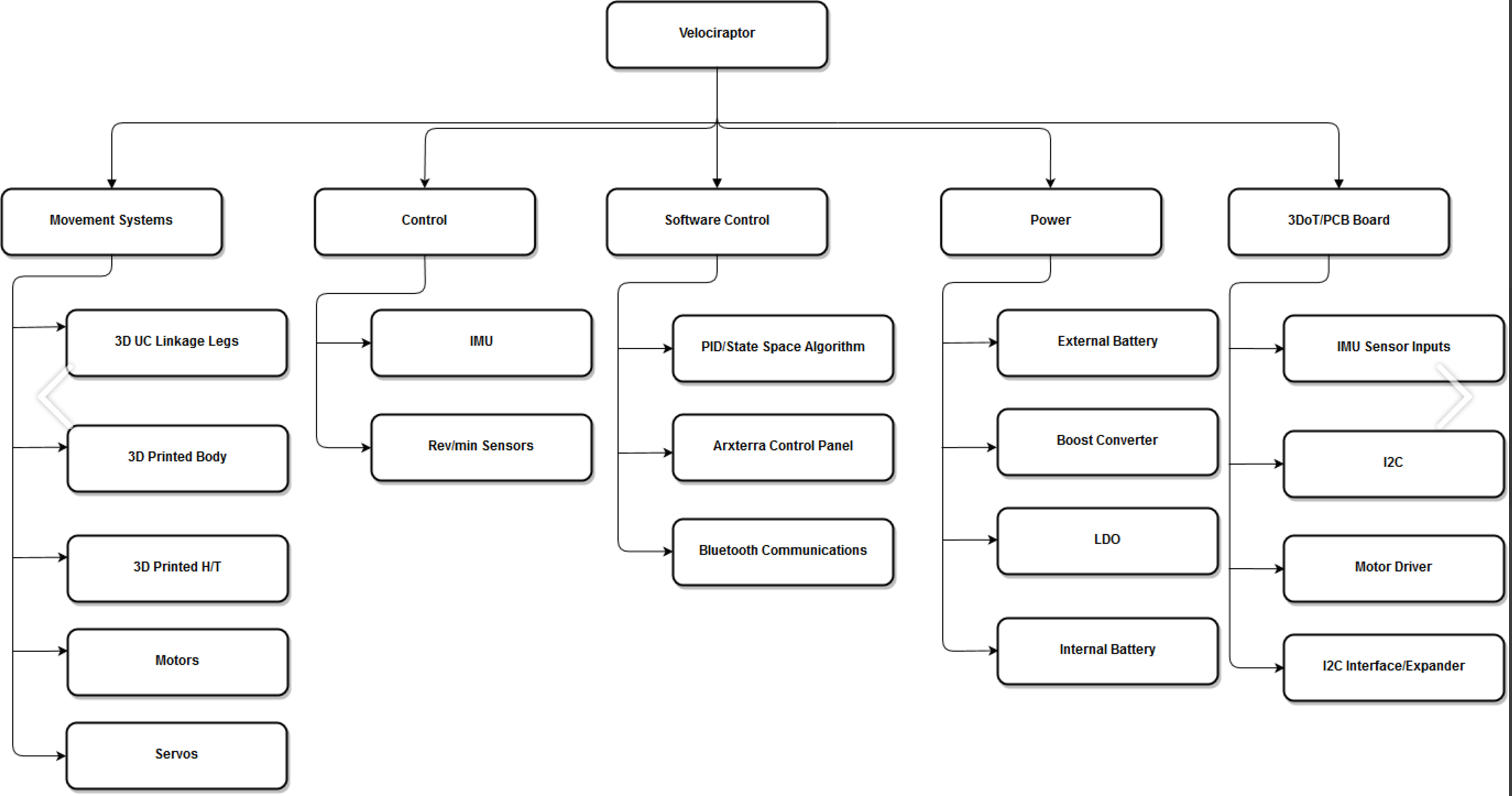
Figure 7. Product Breakdown Structure
The product breakdown structure above was categorized into 5 sections:
- Movement System
- Control
- Software Control
- Power
- 3DoTBoard/PCB Board
The PBS was worked with Paul Auhmada from the Velociraptor (Th) class. The movement system pointed to the mechanical design, servos, and dc motors. The Controls had attributes for sensors. The Software Control had communication and control algorithm code applications. The 3DoTBoard/PCB board was for the external PCB board unique to each projects design.
Work BreakDown Structure

Figure 8. Work Breakdown Structure
The Work Breakdown Structure allocated the task to different divisions of the team. This semester this project the system engineer and the electronics and controls engineer had a huge learning curve therefore there were difficulties to push the project forward in a short period of time. Therefore the system engineer role were covered by both PM’s of each Velociraptor. The electrical and controls engineer role was assisted by their division manager.
Project Schedule
The project schedule indicates the number of tasks needed to follow in order to complete the project. Unfortunately the project reached some obstacles in the electronics and mechanical design.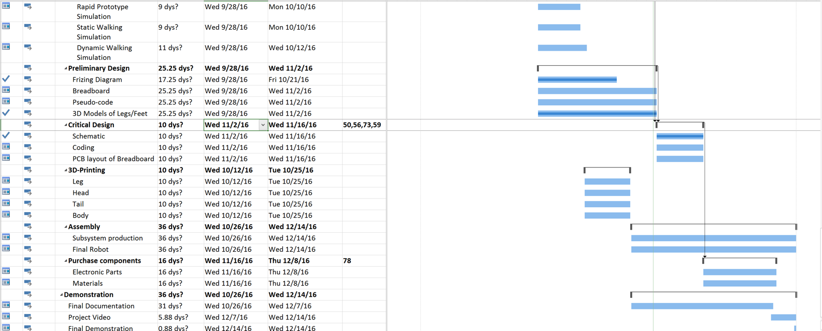
Figure 9: Project Schedule
The burndown structure shows two different graphs where the orange line indicates the tasks remaining to complete the project and the blue line indicates the expected tasks completed. As you can see the path diverged early in the semester, where our systems engineer had reached some obstacles in the task. This problem ended up affecting the rest of the divisions due to time.
The project is marked as 80% complete and needed to implement the feet design of our robot and the control algorithm with the rotary sensor.
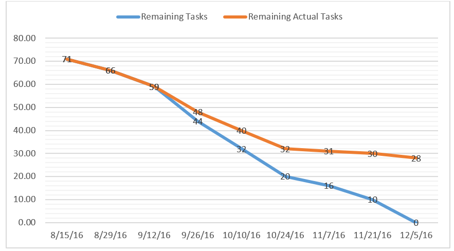
Figure 10: Burndown Structure
Conclusion
The Velociraptor this semester had face many problems to move the project foward. The Theo Jansen Linkages designs was set but when the group assembled our first prototype we noticed that the feet design was one of the issues in having the robot balanced when stationary. There was problems with every division and the delays caused other work to be pushed back. The control algorithm used to move the robot forward and turn was not completed by the final project demonstration. The foot design was one of the biggest problem that needed to be implemented to have the robot balanced when the robot walks.
Future Projects:
- The manufacturing engineering should start on the mechanical design as soon as possible if not then the manufacturer will face bigger problems towards the end.
- The electronics and controls engineer should learn C++ from the start to be prepared for coding tasks.
- The system engineer should not only focus on the requirements but also be ready to think about all factors. Know that the system design is the baseline of the project, therefore if something is changed from the system’s side then there is a possibility this could affect other divisions.
Project Resources
[1] Project Video: https://www.youtube.com/watch?v=1fSIvmpCkRk
[2] Critical Design Review: critical-design-review
[3] Preliminary Design Review: preliminary-design-review and preliminary-design-review PowerPoint
[4] Microsoft Project : projecct-schedule-1
[5] Verification and Validation document: verification-and-validation-test-plan-results
[6] Solidworks File: https://www.dropbox.com/s/9mycah24zwdqag8/Velociraptor.zip?dl=0
[7] Fritzing Files: fritzing-diagram
[8] EagleCAD Files: eaglecad
[9] Control Algorithm Code: control-algorithm
[10] MatLab Code for Torque studies: matlab-code
[11] Complete Bill of Materials (BOM): bill-of-material


