Pick and Place – Preliminary Design Document
Belinda Vivas (Project Manager)
Amber Scardina (Mission, Systems, and Test)
Kevin Ruelas (Electronics and Control)
Tyler Jones (Manufacturing)
Chastin Realubit (Manufacturing)
Table of Contents
Program Objective/Mission Profile
By: Belinda Vivas (Project Manager)
Objective
The second generation of the Pick and Place will create a 3-Dot 454 PC Board. It will ensure precision through the addition of a camera system, addition of a variety of components, design upgrade, and a user friendly mechanism. A CSV file will be created for this generation, to implement a better interface between the user and the machine. A manual will be provided for this generation, as well as for the Madell Pick and Place for which extensive research is being done to implement the design of the camera (edge detection) system and software interface. A more detailed list of the customer’s needs can be found on the link provided.
http://web.csulb.edu/~hill/ee400d/S’17%20Project%20Objectives%20and%20Mission%20Profile.pdf
Requirements
Level 1 Program/Project Requirements
By: Belinda Vivas (Project Manager)
- Through research on the Pick and Place first generation, the Madell Pick and Place, and the customer needs the following requirements will be implemented for the design of the second generation. This requirements will allow to define a clear structure for the design, engineering, and further requirements for the project.
- The pick and place shall have an attached compartment to hold accessories for the pick and place.
- The pick and place shall meet the EE 400D cabinet specifications for storage purposes.
- The pick and place shall incorporate a camera for edge detection.
- The pick and place shall have resources to aid the user of the pick and place in set-up and configuration of the pick and place.
- The pick and place shall have a case to protect the pick and place from its surroundings.
- The pick and place shall produce a 3Dot board in a specified time. This specified time is currently set for one hour, although after trade-off studies are conducted this time may change.
- The user of the pick and place shall be able to set-up and configure the machine in a specified time. This specified time is currently set for two hours, although after trade-off studies are conducted this time may change.
- The pick and place should have minimal movement from outside sources.
- The pick and place shall cost no more than $500.
- The pick and place shall be completed by Wednesday 17th, 2017.
- The pick and place should have an emergency shut off button.
Level 2 System/Subsystem Requirements
Level 2 System Requirements of Pick and Place (1st Generation) Analysis
By Amber Scardina (Mission, Systems, & Test)
Listed above are the Level 2 Requirements for the first generation pick and place. The Level 2 Requirements for the first generation demonstrates the functionality of the current pick and place machine. After analyzing these requirements, the following updates need to be made:
- Size: The pick and place needs to be stored in the EE 400D cabinet.
- More Components: Additional feeders and component trays need to be added to accommodate all components for a complete 3Dot EE 400D board. The reels on the first generation will be removed.
Given the updates listed above, the other level 2 requirements from the pick and place first generation should still hold true for the second generation, exhibiting the same functionality. After trade-off are conducted, more updates and level 2 requirements for the software and manufacturing subsystems may be required in order to successfully verify and validate the level 1 requirements. Additional Level 2 Requirements will be included in the second generation to make the pick and place user-friendly. In the next section below, the level 2 requirements for the pick and place second generation is listed.
Source Material:
- https://www.arxterra.com/spring-2016-smd-pick-and-place-machine-preliminary-design-document/
- http://arxterra.com/goliath-fall-2016-preliminary-design-documentation/#Design_Innovation
Level 2 Subsystems Requirements of Pick and Place (1st Generation) Analysis
By Amber Scardina (Mission, Systems, & Test)
The level 2 subsystems requirements for the pick and place 1st generation can be found in the following link:
https://www.arxterra.com/spring-2016-smd-pick-and-place-machine-preliminary-design-document/
The subsystem requirements should still hold true for the second generation. The system should contain the original manufactured parts (except the reel mechanism), with the addition of new parts to verify and validate the level 2 system and level 1 program/project requirements. The level 2 subsystem requirements helped describe the functionality of the system that will be incorporated into training materials for the second generation.
Level 2 System/Subsystem Requirements of Pick and Place (2nd Generation)
By Amber Scardina (Mission, Systems, & Test)
1. The pick and place shall have an attached compartment to hold accessories for the pick and place. Accessories for the pick and place may include: pump, paste, components, etc.
a. The dimensions of the pick and place and the attached compartment shall meet the EE 400D cabinet specifications.
b. The attached compartment shall not interfere with the functionality of the pick and place machine.
2. The pick and place shall meet the EE 400D cabinet specifications for storage purposes.
a. The legs of the pick and place should be raised to meet of the specifications of the attached compartment.
b. The Z/A axis should not be removed from the pick and place in order to be stored in the cabinet.
3. The pick and place shall incorporate a camera.
a. The camera of the pick and place shall be used to incorporate edge detection technology.
4. The pick and place shall have resources to aid the user of the pick and place in set-up and configuration of the pick and place.
a. The resources for the pick and place shall include a video tutorial on how to handle (set-up) and configure the machine.
b. The resources for the pick and place machine shall include a written manual to assist the user in set-up and configuration.
c. The pick and place shall include sample (test) files for the user to practice with the machine.
d. The resources for the pick and place shall include a section for troubleshooting the machine.
5. The pick and place shall have a case to protect the pick and place from its surroundings.
a. The case shall enclose the machine to meet the EE400D cabinet specifications.
6. The pick and place shall produce a 3Dot board in a specified time. This specified time is currently set for one hour, although after trade-off studies are conducted this time may change.
a. The pick and place shall be faster than human production time. Human production time for a 3Dot board is currently established as four hours.
7. The user of the pick and place shall be able to set-up and configure the machine in a specified time. This specified time is currently set for two hours, although after trade-off studies are conducted this time may change.
Source Material:
1. https://www.arxterra.com/spring-2016-smd-pick-and-place-machine-preliminary-design-document/
2. http://web.csulb.edu/~hill/ee400d/Lectures/Week%2004%20Modeling/b_L2%20Requirements.pdf
Design Innovations
Creative Solutions
By: Belinda Vivas
A creative exercise was executed by the members of the team to begin the process of brainstorming ideas to incorporate new innovative design ideas for the Second Generation of the Pick and Place. Focusing mainly on the problem of mounting the electronic components into the PC Board without them moving out of place. Also, how to implement a better overall design for a more user friendly generation.
https://drive.google.com/open?id=0B9iWYCBTJWEERHB6Y1BHX2owdFU
Systems/Subsystem Design
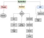
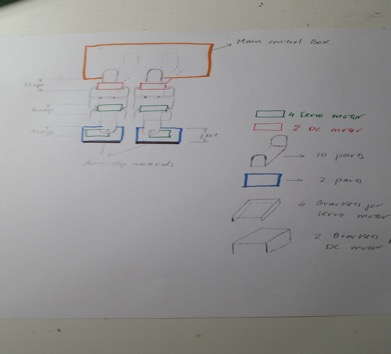
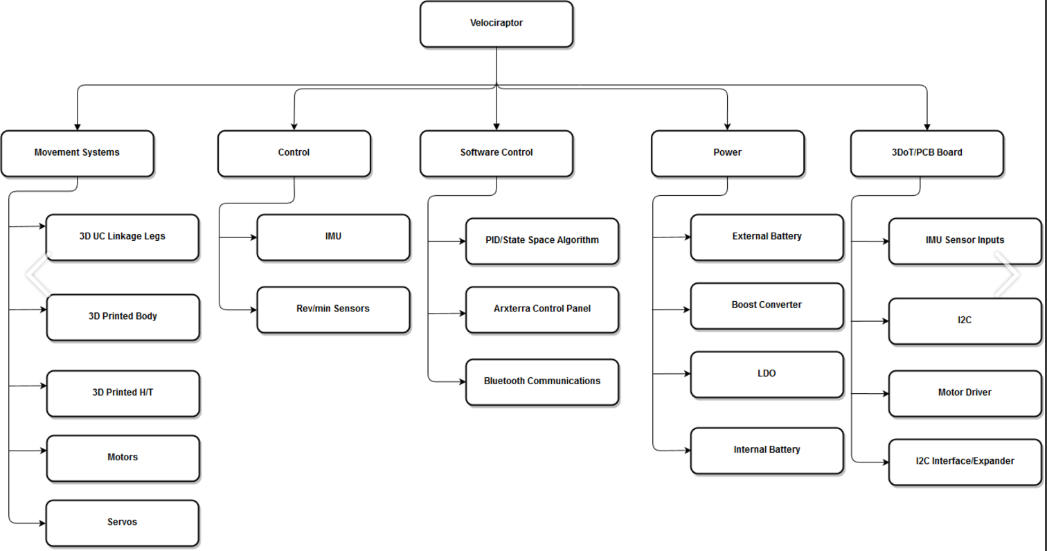
Product Breakdown Structure
By Amber Scardina (Mission, Systems, & Test) and Belinda Vivas (Project Manager)

The Product Breakdown Structure (PBS) demonstrates the updated system and subsystems for the Pick and Place 2nd generation. The updates for the pick and place can be classified in three categories: Customer Interface, Software, and Manufacturing. These categories are described by the Level 1 Program/Project Requirements. The customer shall interface easily with the pick and place machine by giving the customer numerous resources for set-up and configuration. The software will be updated to accommodate customer interfacing, in addition to new edge detection software that will be written for the camera. A possible LCD may be incorporated to display the current electrical components that need to be loaded or placed. The pick and place will also undergo several manufacturing updates. The manufacturing updates on the pick and place includes a nozzle redesign to accommodate a camera to implement the edge detection software. The pick and place machine will also add more feeders and component trays to accommodate a 3Dot board with different type of components as well as an underneath compartment to store accessories for the machine. Accessories for the machine include: pump, paste, stencil, power cords, and electrical components. Other manufacturing additions include updating the specifications of the pick and place machine to accommodate the EE400D closet. After trade-off studies are conducted, the technical requirements for the pick and place 2nd generation will be more clea defined.
Source Material:
1. https://www.arxterra.com/spring-2016-smd-pick-and-place-machine-preliminary-design-document/
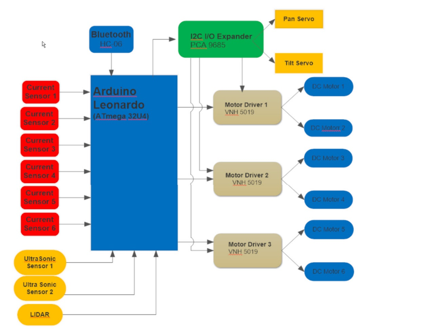
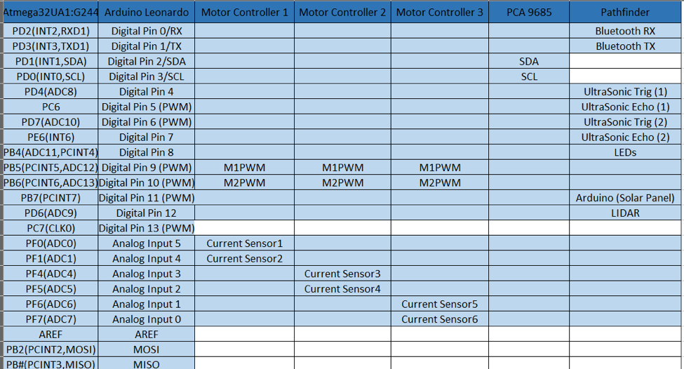
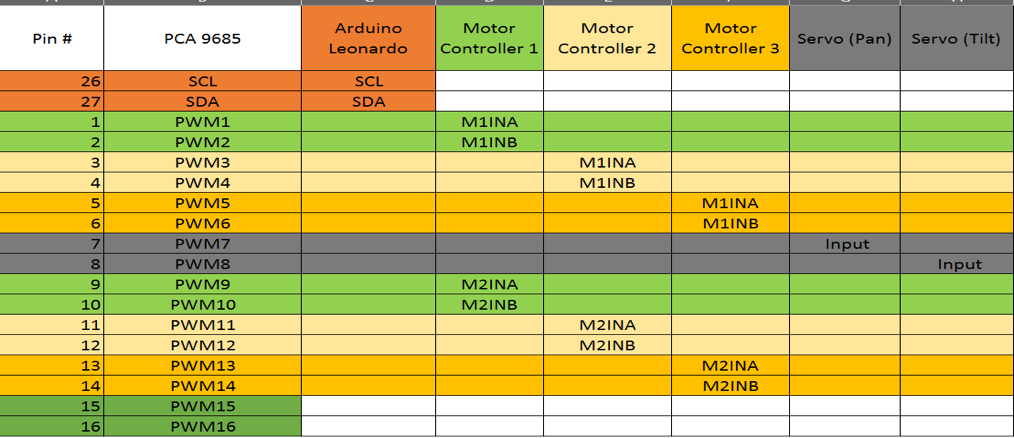
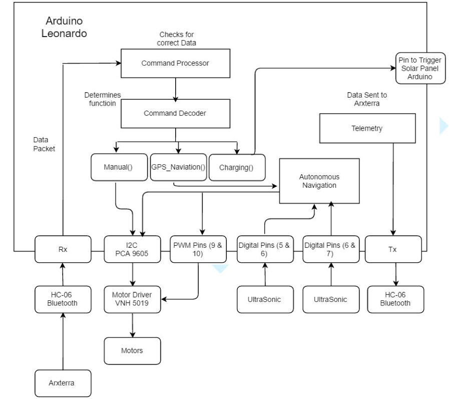
Electronic System Design
By Kevin Ruelas (Electronics and Control Engineer)
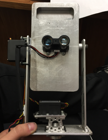
Camera
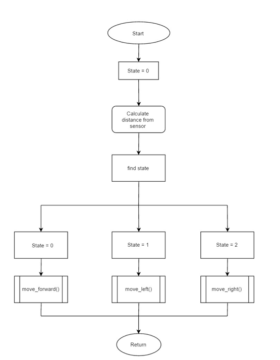
A Cameras should be installed on the machine to incorporate edge detection software. Edge detection will function when the component is picked up and measured and placed onto the board. More research will need to conducted in order to develop the edge detection software.
Another design option: An additional camera can be used to detect whether a component is present on the tray or not and display an “error” message if the tray is empty. Cameras should be chosen so that it is able to capture a high resolution image of the smallest component the machine can pick up. (0402 size). They may also require flash LEDs in order to achieve a bright and crisp image.
LCD
A small screen should be installed and display the current component being picked up and placed onto the board. This display should also display the current status of the machine. Depending on its current operation, a user input pad will be considered. User should be able to input component coordinates and name and press a “Place” button to place the part. Size of the display and place of installation is still pending. Software for the LCD display will need to be developed.
Wires
The wiring for the pick and place should remain unchanged from the first generation.
Button
A kill switch should be implemented to isolate the machine from power in case of emergency or for maintenance. Software for the kill switch will need to be developed.
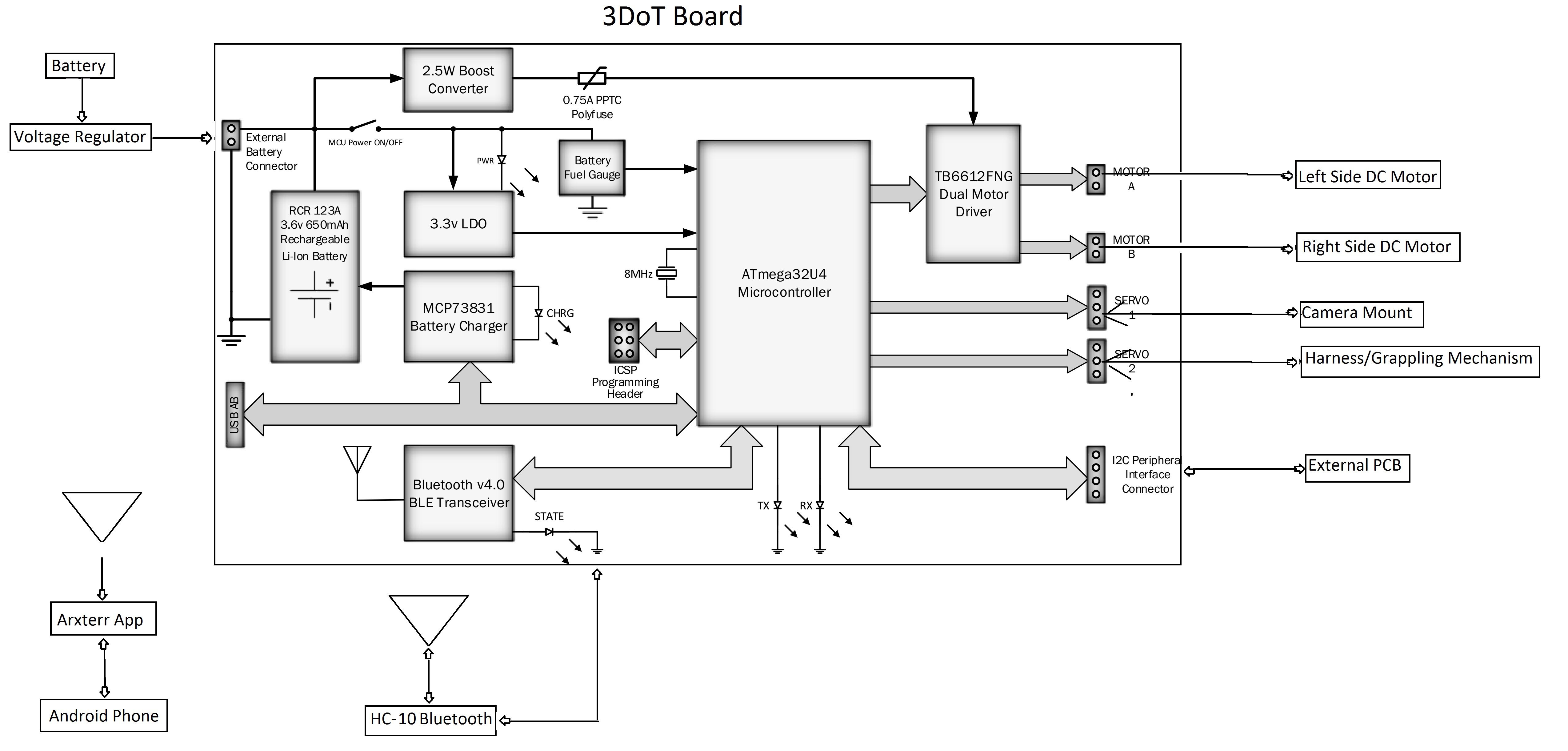
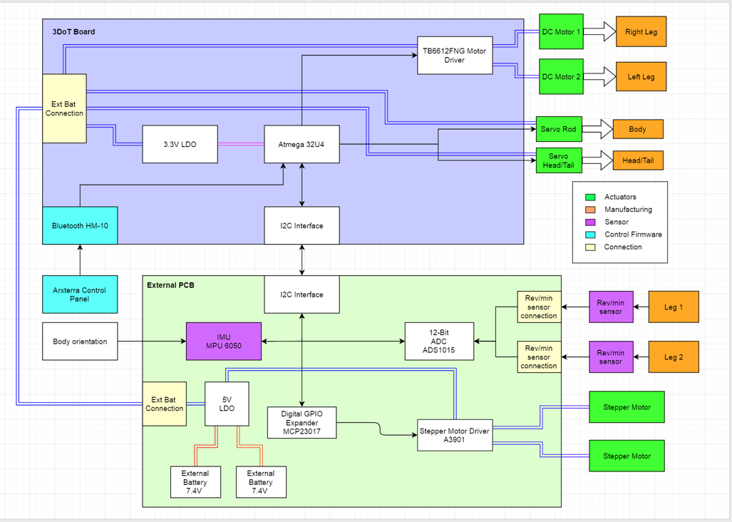
System Block Diagram
By Amber Scardina (Mission, System, & Test) and Belinda Vivas (Project Manager)

The system block diagram above describes the how information is sent in the pick and place system. The information is sent from the user using EagleCad, converted into Gcode, then sent to the microprocessor (Arduino Uno). From the Arduino Uno, the data is sent to a Me Orion board to control the motors for each axis. With the addition of a camera and edge detection technology, the system will allow for calibration of coordinates if necessary. Once the nozzle is confirmed to be at the correct coordinates, the data is sent to
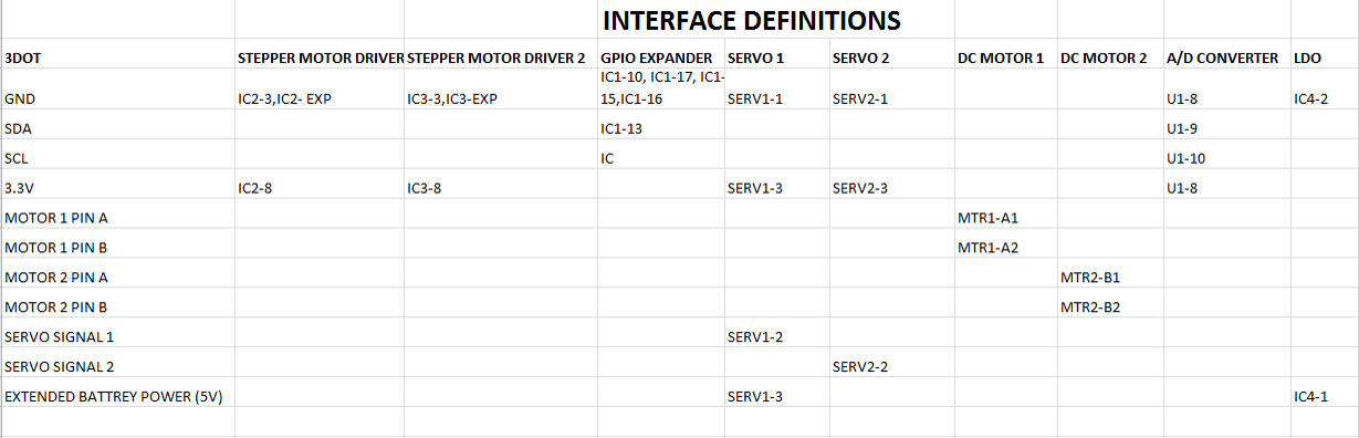
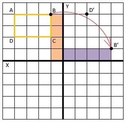
Interface Definitions
By Amber Scardina (Mission, System, & Test) and Belinda Vivas (Project Manager)

The diagram shown above describes how the user will interface with the pick and place. Note: this method has remained unchanged from the first generation.
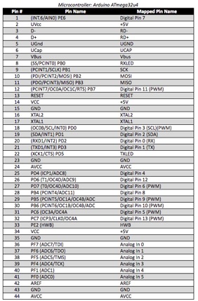
The link below shows the pin mapping of the Arduino Uno, which will be the same implementation for the second generation of the Pick and Place:
Mechanical Design
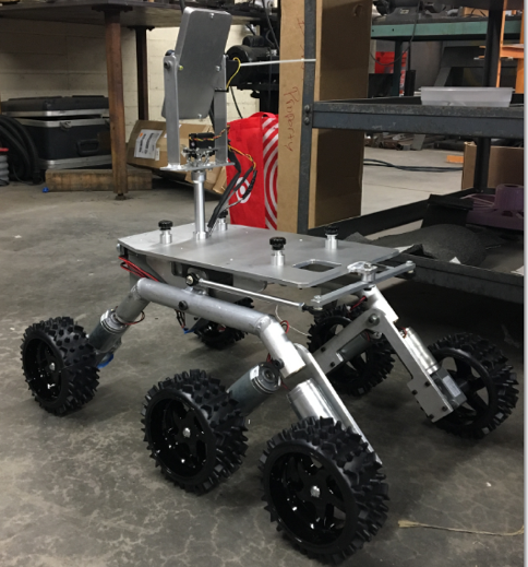
By Tyler Jones – Manufacturing
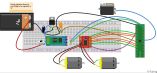
The basic overview of the current design for the pick and place is fully functional and can place 0402 components, as well as larger size components such as integrated circuits and 0603 sized components. The pick and place machine operates on a belt system in the X and Y axes. The Z axis contains the nozzle which can be lower and lifted using a linear actuator. The machine is controlled from an Arduino Uno microcontroller and Me Orion shield. Currently the software is being retested and calibrated for use.
The second generation requirements for the pick and place however will impact the current design. The second generation mechanical design will need to fulfill a size requirement of being able to fit in storage cabinets. Also a much more user friendly design must be incorporated so that the average user can easily manufacture boards without advanced technical knowledge. This will call for a smaller, more compact machine, and must be able to maintain the current precision and accuracy of the first generation. The Z- axis must be able to turn on a geared platform 90 degrees for setup and take down this eliminates the height problem.
The requirements also specify a speedy setup process so that boards may be manufactured quickly. This will call for an all in one style machine without any lose parts. Also the current design implements an automated reel feeder system. This will have to be re -designed however because the second generation will be designed to populate a 3DoT board, using a variety of more components. This renders the reel feeders to be useless because they can only provide thousands of only six types of parts. Additionally the current IC tray must be re-designed because it should also offer a more versatile range of ICs to be used.
In order to fulfill user friendly requirements the pick and place should incorporate a small emergency stop button on the side this will shut off the power to the machine if there are any errors or malfunctions being used. Each of these design elements; the new feeder system, the new sizing, new Z axis that can rotate, and the push button will be discussed further on in this article.
Second Generation Feeder Trays

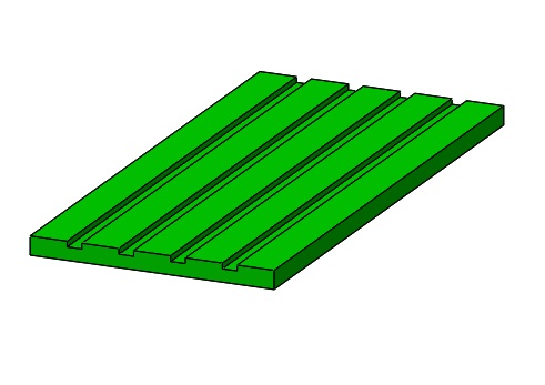
The feeder trays can be made so that the grooves fit a universal tape reel size. This will allow multiple types of tape sizes to be fit into the grooves.
The trays can be 3D printed using ABS plastic and color coded according to part sizes.
Multiple trays can populate the table so that all parts can be utilized by the machine.
The groove size for the tape reels to fit snugly without stalling the tape is 0.317 inches.
The length of the groove should be enough so that at least 30 of each part can fit. This will safely cover the maximum number 3DoT board’s parts that are identical for each individual board design.
A tape peeling and reel feeding mechanism may have to be employed after exploring the software capabilities.
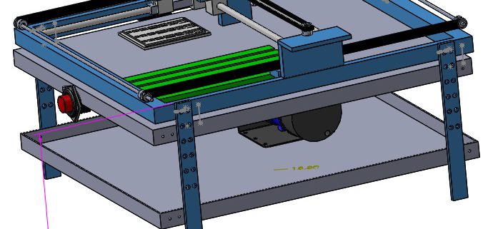
Downsizing Second Generation Pick and Place
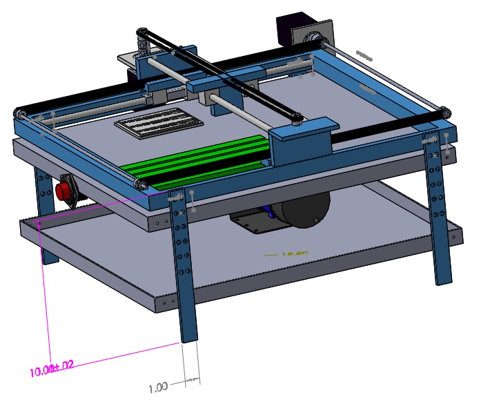
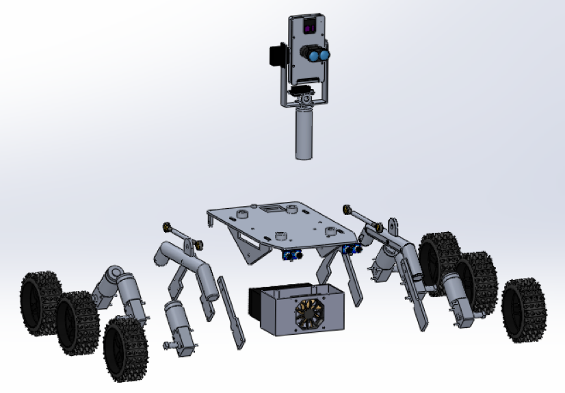
The 2nd Generation Pick and Place must be made smaller. This is so that the machine can be easily transported, and setup for ease of use. The image above represents a solid works draft of the machine. The legs can be lengthened by 4 inches providing a space below the pick and place so that the pump can be mounted.
This also makes it so that the pick and place can be stored in a cabinet in the upright position. It provides a convenient area to have the used part tape land, as well as an area for putting the spare components or component strips. The under tray can be made from aluminum or sheet metal so that the pick and place is still lightweight.
Getting rid of the reel feeder system provides more stability, because there is no longer an aluminum feeder and large reel hanging from the side of the machine. This also cuts down on height and width, as well as weight.
The absence of a reel feeder also creates more surface area to populate the picking surface with more IC trays and cameras.
Rotating the Z-Axis
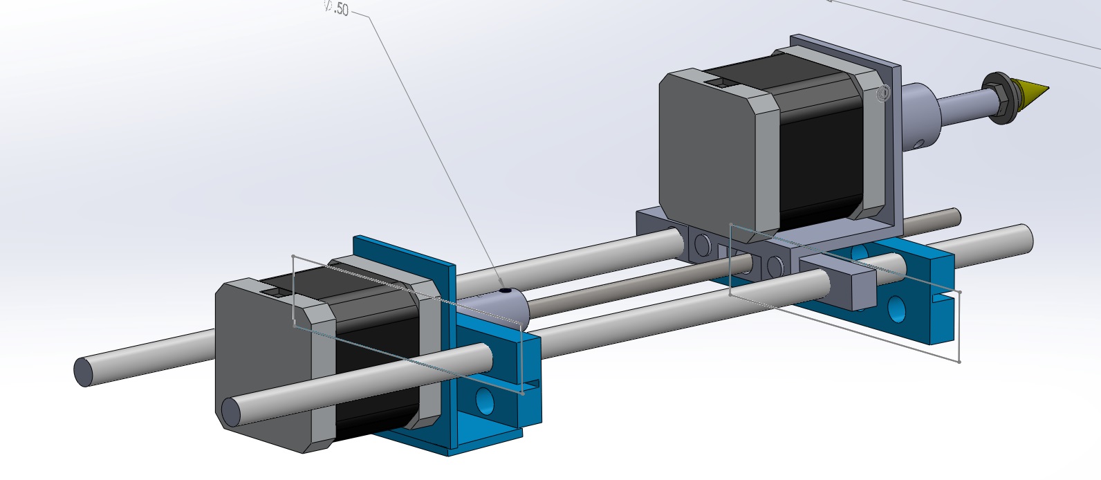
The diagram above shows how the Z – Axis can be rotated by 90 degrees from vertical to horizontal.
Using a rack and pinion the whole Z – axis can be rotated and locked into position. This allows for more height clearance and ease of use. The Z axis stands 7.5 inches above the XY Axis. Allowing the Axis to be locked in 90 degrees from the Z axis eliminates all but about 1 inch to stand above the Axis. This creates enough room to store in a cabinet.
It is essential that the locking mechanism be very tight in order to prevent misalignment. It is also essential for the mechanism to be simplistic and small itself.
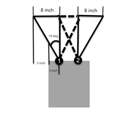
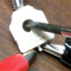
Emergency Button
![]()
![]()
![]()
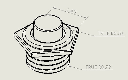

The schematic above shows the sizing and dimensions for the emergency push button. This will be implemented as a way to stop the machine from processing any further components. The position of the button needs to be within reach of the operator, and on the same axis as where the parts are placed into the grooves.
Depending on the software development the emergency button may be implemented in power circuit as an override switch.
Design and Unique Tasks
By Amber Scardina (Mission, System, & Test) and Belinda Vivas (Project Manager)
Trade – Off Studies
Several will be conducted in the following weeks to confirm our level 2 requirements. The tradeoff studies conducted:
· Set Up time – The time to set-up and configure the machine by the user will be measured.
· Production Time – The time to pick and place an entire 3Dot board by the user will be measured.
· Material of Case – Possible materials of the case will be tested in order to support the weight of the pick and place machine.
· Material of Compartment – Possible materials for the compartment will be tested in order to set the weight specifications for the pick and place machine.
· Size of Component Trays – The “free space” on the pick and place machine will be measured to set the size specifications for the additional component trays.
· Size of the EE400D Cabinet – The EE 400D cabinet will be measured to set the size specifications of the pick and place machine.
Modeling
The modeling for the second generation pick and place should follow the software design of the first generation. Mechanical design will be upgraded for a more user friendlier generation and better calibration system.
https://www.arxterra.com/spring-2016-3d-smd-final-documentation/
Rapid Prototyping
The pick and place should be functioning as it is defined by the final documentation of first generation. The pick and place machine is currently in progress on setting up, running the software, and checking the wiring connectivity. Depending on how the tests run to implement the software we will decide on introducing a new software for the second generation (OpenPnP).