“HEXAPOD – the Movie” Trailer
By Mason Nguyen – Project Manager
A short trailer that was filmed by our team during this semester!!!
https://www.youtube.com/watch?v=3NniqIkw-64&feature=youtu.be
By Mason Nguyen – Project Manager
A short trailer that was filmed by our team during this semester!!!
https://www.youtube.com/watch?v=3NniqIkw-64&feature=youtu.be

By Maxwell Nguyen, Project Manager
During the field presentation of the rover, spiderbot, and hexapod, all three groups were able to successfully launch their projects. However, all three groups encountered a few similar problems that prevented the projects from completing the mission objective.
Level 1 Requirements:
The height requirement of the rover was completed and verified. The rover was able to move over the sprinkler as well as roll over smaller obstacles on the field. It was able to drive over small twigs and pinecones without tipping over. The power of the rover was sufficient to drive itself the entire course. However, the rover was unable to complete the entire course due to connection issues. The mirror system was able to provide the rover proper vision during the mission. The pan and tilt in junction of the mirror are fully functional.
Troubleshooting and Issues:
We noticed that connection to Arxterra was extremely weak and limited on the field site. This was not an issue due to lack of wifi signal. Even though the wifi source was in range, strong, and secure, connection to Arxterra was not stable. The rover was only able to connect to Arxterra for a few seconds before being disconnected form the website. We believe that this was due to all three projects trying to connect to Arxterra at once. There seemed to be no connection problems when only one robot was connected to Arxterra. However, if multiple robots were connected to Arxterra at the same time, connection would be extremely limited. Even then, there were other issues running with Arxterra.
The rover suffered from latency problems while running the course. When inputting commands for the rover, there would be a rough estimate of one second delay before the rover reacts to the commands. At times, the latency would be so great that the rover would not receive any commands at all. This again was not due to the wifi signal to the phone or the labtop. All components of the rover were active but was not receiving any commands through the labtop. However, this issue only appeared several times and was not a consistent problem.
If this project is recreated, it is strongly advised to test in junction of other projects instead of individually. By running field tests with other projects, problems with Arxterra and wifi connection can be more accurately identified and fixed.

By Matthew Clegg – Computer & Control Systems
With the final model of Spiderbot finally up and somewhat running, coding for communication between Spiderbot and the Arxterra control panel, via the Arxterra Android App has gone underway. With help from Tommy Sanchez of Robot Company’s MC3, I have managed to implement the code to enable communication with the control panel.
The following link is a video of basic movements available on the Arxterra control panel as applied to Spiderbot:
Prior to the time of recording, one of Spiderbot’s legs twisted so Spiderbot is placed on top of a toolbox for support, so movement has been shown in slow motion to give a better idea of what the actual Spiderbot movement is.
This link will lead to base instructions that were written to help with connection between the Arxterra Android App and Control Panel:
By Mason Nguyen, Project Manager
For a project, it is important to have well prepared detailed budgets cost in order to meet its goals and objectives. Detailed budgets will be included with the name of the item, item quantity, production location, shipping cost and total cost. Here is our final budget report.
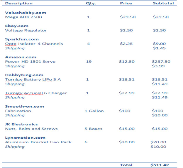
Following from the presented mission objective budget that was stated here (https://www.arxterra.com/mission-objective/), our team managed and maintained the budget within $500 range. In comparison to previous projects, our budget seems to be the lowest because we used an ADK board where it has a built in USB slot. Link to ADK board (https://www.arxterra.com/hexapod-adk-board/)
However, for the Arduino Uno it does not have a USB slot so the user needs to buy another board that has a USB slot and connect it them together. In addition, the Arduino Uno does not provide enough space to connect all 18 pins for the servos. It requires the user to use two ADA fruit servo shields to connect all the pins together. Our team budget could have been less than $500 since we only needed 18 servos to operate the hexapod but we added an additional servo as a phone holder to observe and scan the area.
By Tien Dang
Introduction
During the project (hexapod), we broke total of four servos. After observation and analysis from the broken servos, we able to detect and identify two problems of how the servos were broke down, while the servos are running. First problem we encountered is overload in power, and the second problem is overload in weight. So we took some time looking inside of the broken servos and found few solutions way to fix them.
What does inside of a servo look like?
Servos usually contain three parts (metal grinding gears, motor and circuit board)
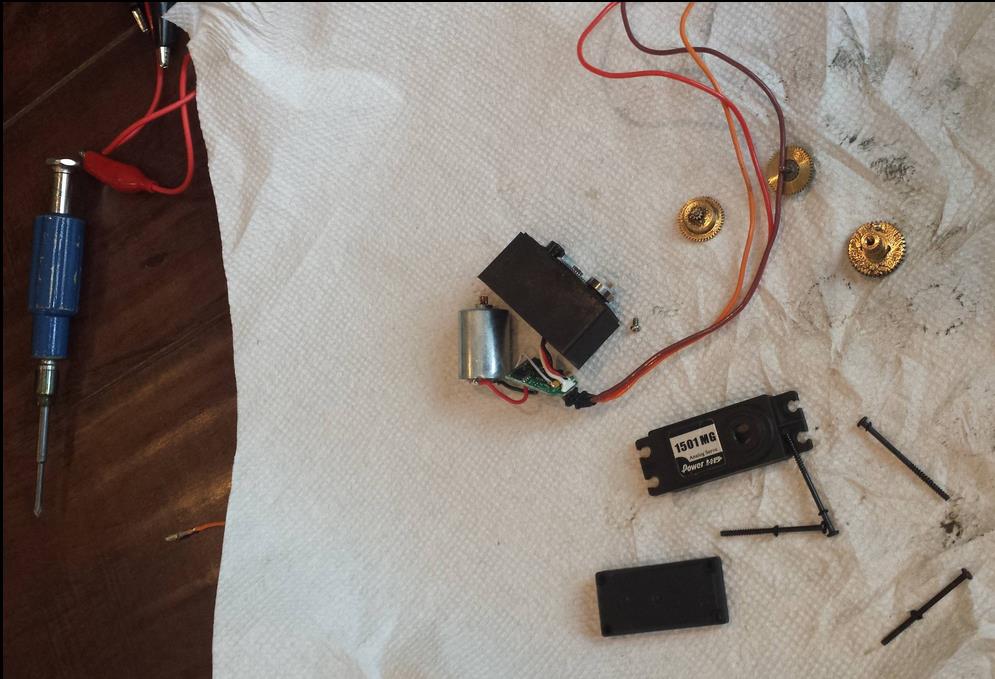
Figure 1: Take apart servo with a screwdriver
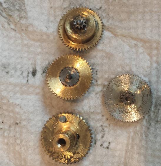
Figure 2: Metal gears
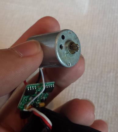
Figure 3: Motor and circuit board
How to fix broken servos?
To detect which problem servo met, we connected the servo to the board as we testing the servo.
This problem is usually meet when we first buy the servo and test right away without adjust the voltage to 6V or limit the current that goes by the servo.
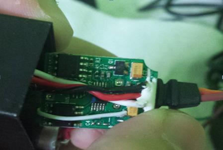
Figure 4: Circuit board inside the servo
For the power problem, three cables (black, white, red) will usually falling off from the soldering node or the chip is tanned. If the soldering parts are failing off, simply re-soldering it, if the chip is burnt, we have no choice but to replace the whole board (use the broken gear servos to exchange the board)
2. Weight overload
This problem usually occurs when the team is testing the hexapod movements (forward and backward). The weight distribution usually does not equal for each legs, all of the weight will be putted on the back legs (which simply cannot create enough force to push the whole body moving forward). This will result into two problems. One is current over-drain, and the other is broken gears metal.
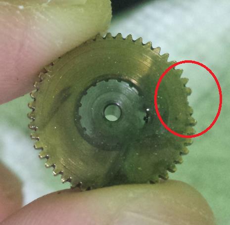
Figure 5: Broken gear metal
For the current over-drain problem, we can repair it by using the same methods as power overload. For the broken gear metal, we need to replace the gear. We can buy the new metal gears online at the website http://www.amain.com/advanced_search_result.php?keywords=metal+gear&x=0&y=0. Then we can exchange the broken gear with the new ones. Instead of paying $12.50 to buy a new servo, this method will save a lot of money since one metal gear only cost $0.99 up to $4.99 compared to $12.99.
Conclusion
After looking inside four broken servos, I was able to exchange metal gears and burnt board for two of the servos. They are working and running smooth like a brand new servo. In case if we stumbled into this problem again while demoing the project, I will be able to dismantle the servo apart less than 5 minutes and exchange the broken parts without taking the whole hexapod apart (like we did from beginning). Save time and money!
Here is the picture that I replaced and exchanged metal gear without take apart or re-wiring the robot.
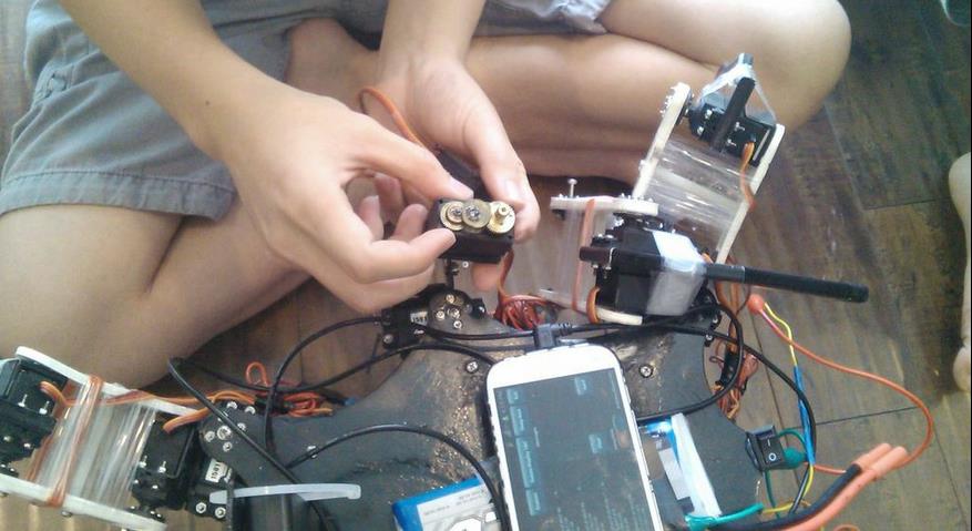
Figure 6: Exchanging the broken metal gear for one of the leg.
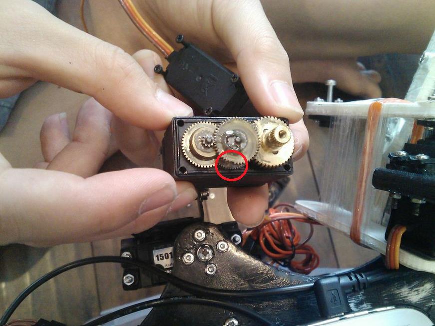
Figure 7: Broken metal gear in middle leg’s servo

By Vinh Kim, 3D model and manufacturing

Figure 1: Here we will be using Smooth-Cast 300.
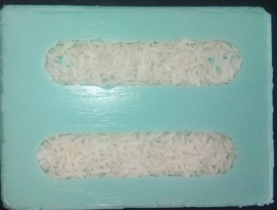
Figure 2: I used rice to measure the volume or you could go online at http://www.smooth-on.com/tools.php to use a Material Calculators “How much liquid plastic do I need?”
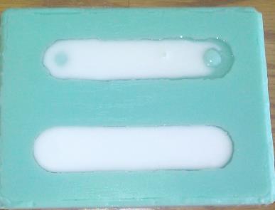
Figure 3: Using the resin molding Smooth-Cast 300, we will be mixing .55 oz for cup A in one and .55 oz for cup B. During the mixing process, make sure to pour the liquid from cup A into cup B and blend it fast (the resin will harden in 3 minutes so make sure to mix it fast) and carefully pour the combined mixture into the rubber.
At this time, the resin will turn white, so let it cool down for about 15 to 30 minutes than take it apart. Now, you have to wait about 10 to 14 more hours, before the casted parts can be machined.
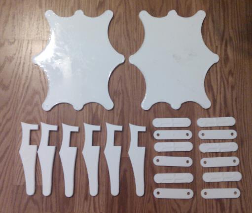
Figure 4: Casting done.

By Kristine Abatay – Project Manager
The following figure is a table of the total amount spent in creating the final model for Spiderbot:

Two total values are provided in the far right columns. The orange column projects the total amount that was spent in completing the overall project. The green column excludes any costs spent on material that was a result of experimentation. For example, the initial mold that was created for Spiderbot’s tibia piece was not used for the final tibia pieces, so its cost was removed from the final green column total. The same goes for some of the costs included in the orange column for casting resin material. There are three breakout boards included in the orange column costs because one of the boards was damaged, as mentioned in a previous blog post.
The items that are listed with two prices, separated by a backslash, indicate that two separate totals were paid for those components. In the case of the casting resin, our 3D modeling and manufacturing member, Simon Abatay, managed to find coupons and deals, so those materials purchased in-store were much cheaper in price. This route of purchasing smaller containers of the material in-store, was taken because purchasing everything in bulk online would have been too expensive and would have resulted in too much excess material.
The total cost came out to be much larger than expected (the expected total was somewhere in the $600 range), but many things were learned in doing so. Much more money was spent in the silicone mold maker material compared to last semester because the pieces used in this semester’s Spiderbot were more three-dimensional and voluminous by nature, so naturally, more material was required. An innovative method for producing casted pieces with less material was also found because so much money was spent to fund the experimentation portion of manufacturing, so maybe this grand, albeit scary, total was a good thing.
By Chau To
This blog post will introduce how to code and connect the Arxterra control panel into the Android phone. The Android phone that the Hexapod will use is to connect the Arduino ADK via the USB port. In order to link between the Android phone and the ADK, the user needs to download the adb.h library. Please contact the instructor or the division manager for download link.
Basically, the Arxterra control panel will send the command to the Android phone and from through the phone; it will communicate with the ADK via the USB port. The command from Arxterra is 5 byte (the last 5 byte of the 16 byte command series). It’s stored in the array called “data”. This is the list of the byte that the Arxterra sent out; the “xx” means that these bytes will change every time the user presses the button.
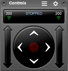
MOVEMENT CONTROLLER:
Forward: 01 01 xx 01 xx
Turn Right: 01 01 xx 02 xx
Backward: 01 02 xx 02 xx
Turn Left: 01 02 xx 01 xx
NOTE: This data only valid when the user presses stop between each command. For example, if user wants to turn right after walking forward, they have to press the stop button (the middle button).

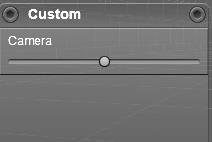
CAMERA CONTROLLER:
Left: 02 00 xx 00 xx
Right: 02 00 xx 00 xx
Hexapod does not use camera controller tilt up and tilt down, but the concept is very similar.
The 1st byte data[0] is the command ID. Each controller will have a different command ID. Movement is data[0] = 01, Camera is data[0] = 02. So, we can compare the value of the command ID to control the robot.
The next step is to compare the 2nd value of the array data[1]. For movement, data[1] of forward and right turn in equals, and data[1] of backward and left turn is equal. Therefore, we will continue to compare the 4th value of data[]. The data[3] will be compared to decide that what movement the robot will need. With a couple of if…else statement, we can determine the action of the robot.
The data [2] and data[4] is varied overtimes because Arxterra was initially designed for the ROVER, and those byte were to control the speed of the DC motor. So do not worry about those bytes!!
Remember that you have to press stop before switching to a new command.
For CAMERA controller, the command ID is data [0] = 02. The third byte data[2] and the fifth byte data[4] is actually the angle when you convert from HEX to int.
Since the Hexapod team this semester uses only 1 servo to control the camera (turn the camera left or right), we decided to create a custom command. The custom command is a very powerful tool to add a new desired controller. The custom command is provided on the Android Arxterra Apps on the phone. When the custom command is created, it will appear on the Arxterra website controller.
The custom Camera that I created will have a command ID of 0x04, initial value is 0, maximum value is 40 and minimum value is -40. Each increment by 1, the servo will move 2 degrees.
This is the Sample Code for the Arxterra testing:
#include <SPI.h>
#include <Adb.h>
#define FALSE 0
#define TRUE 1
// Commands to Numeric Value Mapping
// Data[0] = CMD TYPE | Qual
// bit 7654321 0
#define MOV 0x01 // 0000000 1
#define CHOICE 0x02 // 0000001 0
#define CAMERA 0x40
// Adb connection.
Connection * connection; // the connection variable holds a pointer (i.e. an address) to a variable of data type Connection
// Event handler for the shell connection.
void adbEventHandler(Connection * connection, adb_eventType event, uint16_t length, uint8_t * data) // declared void in version 1.00
{
// Serial.print(“adbEventHandler”);
// Data packets contain two bytes, one for each servo, in the range of [0..180]
if (event == ADB_CONNECTION_RECEIVE)
{
Serial.print(“rover received command “);
uint8_t cmd = data[0];
uint8_t cmd2 = data[1];
uint8_t cmd3 = data[3];
uint8_t cmd_cam = data[2];
if (cmd == MOV) {
Serial.println(” MOVE “);
if (cmd2 == MOV){
Serial.println(” Forward or Turn Right “);
if (cmd3 == MOV){ Serial.println(” Move Forward “);}
else if (cmd3 == CHOICE){ Serial.println(” Turn Right “);}
else { Serial.println(” Stand “);}}
else if (cmd2 == CHOICE) {
Serial.println(” Backward or Turn Left “);
if (cmd3 == CHOICE){ Serial.println(” Move Backward “);}
else if (cmd3 == MOV){ Serial.println(” Turn Left “);}
else { Serial.println(” Stand “);}}
else {Serial.println(” Stand “);}
}
else if (cmd == CAMERA) {
Serial.println(” CAMERA “);
int fone_ang = int(data[1]);
if (fone_ang <= 40){
int ang = 90 – fone_ang*2;
Serial.print(“Angle: “);
Serial.println(ang,DEC);}
else{
int ang = 90 + (255 – fone_ang)*2;
Serial.print(“Angle: “);
Serial.println(ang,DEC);}
}
else {Serial.println(” Stand “);}
}
}
void setup()
{
Serial.begin(57600);
Serial.print(“\r\nStart\n”);
//init_servos();
ADB::init(); // source of OSCOKIRQ error
// Open an ADB stream to the phone’s shell. Auto-reconnect
connection = ADB::addConnection(“tcp:4567”, true, adbEventHandler);
// insure motors are off and turn off collisionDetection
// stopMotors();
}
void loop()
{
ADB::poll();
}
Upload and Open the Serial Monitor (Ctrl+Shift+M) to test it.
SPECIAL THANKS TO VINH KHOA TON and TOMMY SANCHEZ !!!
By Chau To and Elaine Doan
Design:
Servos:
Microcontroller and Servo Controller:
Communication:
Link to Arxterra compatibility (https://www.arxterra.com/android-phone-complications-with-arxterra-robot-application/)
Power:
Current testing is available at https://www.arxterra.com/current-draw/.
Link to Mission Objective is here https://www.arxterra.com/mission-objective/
By Mason Nguyen, Project Manager
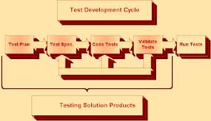
In order to build a successful project, it is important that our team to develop an effective test plans and schedule to manage our assignments. Our test plans will be divided into four categories where each member is expected to perform and complete.
3D Model:
A hexapod model will be designed through our manufacturer Vinh Kim. He will be using Solid Works program to perform stress test, materials test and create initial 3D design for our hexapod. The timeline to complete his assignment is 7 weeks. Down below is Vinh’s roadmap break down.
3D Modeling: 1.5 Weeks
Solid works and materials testing: 3.5 Weeks
Manufacturing: 2 Weeks
Power:
To support the hexapod movements, servos will serve as the primary pillar for the hexapod to walk. Meanwhile, the battery will be the main component to power up the hexapod. To understand more about servos, several testing experiments will be conducted to test its functionality such as angle, rotation, current and torque. This assignment will be performed by the project manager and it will take 10 weeks to complete. Also components will be ordering based on the trade-off study from the servos and battery.
Servo testing and requirements: 3.5 Weeks
Battery testing and requirements: 2.5 Weeks
Ordering Supplies: 4 Weeks
Programming:
Programming will be the most difficult task due to many requirements of the servos angle and rotation. To complete this assignment, our team computer engineer Chau To will be given 10.2 weeks to run various tests and calculations. His roadmap is defined below.
Servo calibration testing: 2.5 Weeks
Software testing: 8 Weeks
Communication:
Using an android phone, the hexapod will be controlled wirelessly from Arxterra interface. Tien Dang who’s our communication engineer will be responsible to perform the Arxterra coding and testing integration. His assignment is expected to complete within 8 weeks. He also will be helping out Tommy with Arxterra interface. His road map is defined below:
Arxterra testing requirements: 4 Weeks
Arxterra coding: 4 Weeks
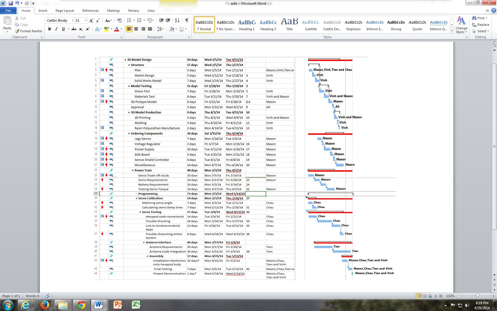
As shown in the schedule, the team has performed and completed all of our tasks. Our final finishing touch will be demoing process and a short movie clip to wrap up our project.