Spring 2016 Velociraptor: Spring Experiment

By: Mingyu Seo (Manufacturing & Design Engineer)

Introduction:

After assembling the final prototype and testing the static walk, we’ve found the weight of the head and tail were straining the servos. We’ve decided to use a spring to support the weight, which lead us to perform a quick experiment to see how much the spring will help support the weight. A variety of miscellaneous items were use as mass to test the spring constants.

Procedure:

s3

Figure 1. Experiment procedure

Figure 1. shows the experimental procedure to test the spring. We’ve added weight to see the extension of the spring, and to see how much the spring will be able to support with maximum of 300 grams due to our head and tail only weights 200 grams with the battery included.


s2

Figure 2. Experimental Data


s1

Figure 3. Attached spring to the head of the robot.

Conclusion:

By adding a spring we were able to reduce majority of the stress applying to the servos. By removing the stress on the servos we also conclude that it reduces the power intake of the servos because the servos no longer hold the full weight of the head and tail. To see how much power is consume refer to the servo load test blog post.

Design(s) of 3D printed attachments Spring 2016

Posted by: Luis Valdivia (Project Manager)

Written by: Juan Mendez (Manufacturing Engineer)

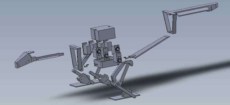
Our vehicle has a yaw problem which causes it to be unstable. After brainstorming a few ideas, we have decided to attack this problem by adding on attachments in order to perform thrust vector control using servos and also be adding flaps to redirect the direction of the thrust.

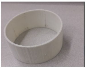
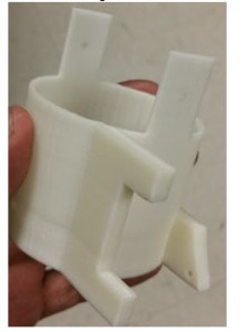
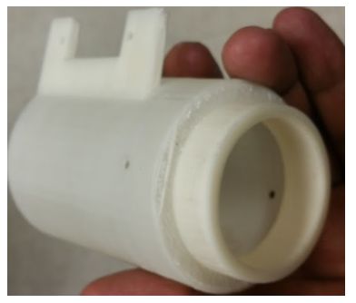
Before making our design, there were several parameters that we had to take into account such as ensuring that the attachments fit the ducted fans. For one we needed to keep the attachments as light as possible to not add on too much weight on to the vehicle however we could not for too light for several reasons. The parts that were 3D printed needed to be no less than 2 mm thick. The reason for this is because the 3D printer that we were using could not print any less than that. We first had a prototype printed to see if we could use a 3D printed part that was the thin. Once we had printed it, we saw that the part was way too thin to use and was easily broken. In order to make sure that the attachments weren’t too thin to break, we increased the thickness to 2.54mm which is roughly .1 inches thick. Once we printed a small prototype, we saw that it was much more durable than the 2mm one and we were able to easily drill through it without breaking as seen in Figure 1. 

Figure 1  3D printed duct attachment 

duct ring

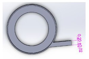
The next minor challenge that I had to consider was being able to mount on servos to the attachments. The servos were measured to have a height of 1.18 inches and needed to be mounted on to the cylindrical shape. We were initially going to make brackets and screw them in to lock the servos in place however it would be a challenge since we did not have a flat surface and we did not know if adding on screws into the attachment would affect the air flow. After consulting with my project manager, he suggested extruding a thin block out of the attachments and then mounting them onto their. I went with this suggestion and properly dimensioned the extrusion to fit the servo. Initially I designed the extrusion block to be roughly 1x .2x 2.25 inches in size. From there I made an inner cut that was .53x 1.19 inches so the servo can easily fit in (Figure 2). I had these printed and checked to see if both servo EDF could fit on to the attachment. Sure enough both did. In order to secure the servo, I had to drill into the extruded block. For this reason I made the block .2 inches thick, so it would not break off when drilling (Figure 3). Once making the holes, the servo was easily mounted on to the attachments.

Figure 2 CAD of thrust vector chamber with servo flaps (side view)

side view of chamber

Figure 3 CAD of thrust vector chamber with servo flaps (top view)

top view of chamber

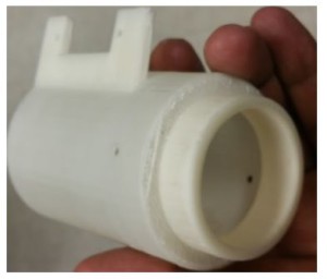
        Next we had to make sure that these attachments fit into our Electric Ducted fans. The ducted fans that we were using have an outer diameter of 53mm. I dimensioned the attachments to be slightly bigger than this in order for it to be able to slip on to the EDF. In order to not waste material and time, I had only one attachment be printed. Sure enough it did not fit and was way too tight to even slip on without damaging the attachment. I made designed the attachments to have roughly an inner diameter of 54.1mm which was approximately 2.13 inches (Figure 4) with an outer diameter of 2.23mm (Figure 5). Once making the adjustments, we were able to slip on the prototype into the EDF.

Figure 4  CAD of thrust vector chamber demonstrating inner diameter

idkwhatthisis      

Figure 5  CAD of thrust vector chamber demonstrating outer diameter

idkwhatthisis2

        Since we were going into thrust vectoring, I needed to make sure that the servos could move the attachments without causing any problems. One of the issues I noticed when designing the attachments was that after it rotating roughly 45 degrees, there was going to be a gap that would make air leak out, which could cause an addition issue when trying to stabilize the vehicle. To fix this problem, I made an inner cylinder to close off the gap and made it to have an outer diameter of 1.75 inches (Figure 6) and a length of 1 inch (Figure 7). Because of this, when the middle attachment rotated, there was no gap to leak air. The fabricated part can be shown in Figure 8A & B.

Figure 6 CAD of thrust vector chamber demonstrating inner diameter (second level)

idkwhatthisis3

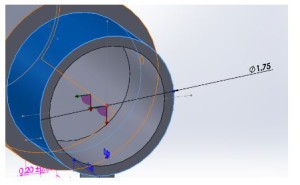
Figure 7 CAD of thrust vector chamber demonstrating outer diameter (second level)

idkwhatthisis4

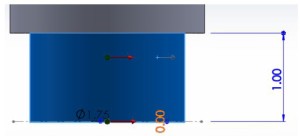
Figure 8A 3D Printed thrust vector chamber (side view)

idkwhatthisis5

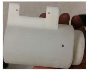
Figure 8B 3D Printed thrust vector chamber (alternate view)

idkwhatthisis6

        Next was to design the middle attachment. The middle attachment was a much simpler design since much was learned from making the top one. This one just needed to have an inner diameter that was slightly bigger than the top one so it can fit and move. In order to give it a bit more space to move, this attachment had in inner diameter of 2.3 inches (Figure 9). In order to mount on this attachment to the top one, I made the mounts to be roughly 1 inch tall to compensate for the inch clearance that was given from the top attachment. I made a pilot hole on this that is in the center of the mount which was roughly .5 inches from the top of the attachment (Figure 10). An extrude block was added on to this attachment as the previous one, however an additional extrude block was added on in the back in order to have the servo joint attached on to it (Figure 11). There, the top servo was going to push and pull on to this attachment. Ideally this part was not meant to be this long, however we needed to give enough space for the servo. To control the bottom attachment. The fabricated part can be shown in Figure 12.

Figure 9 CAD of thrust vector chamber demonstrating inner diameter

idkwhatthisis7

Figure 10 CAD of thrust vector chamber attachments

idkwhatthisis8

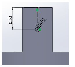
Figure 11 CAD of thrust vector chamber (second level)

idkwhatthisis9

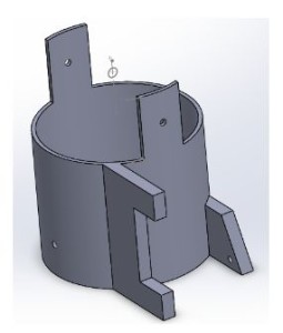
Figure 12 3D Printed thrust vector chamber

idkwhatthisis10

        Lastly we needed to make the bottom attachment. This was the simplest design since it was a funnel shape. In height, the funnel ended up being roughly two inches. As before, an extruded block was added on to this but just to connect to the servo, not to mount on (Figure 13). The fabricated part can be shown in Figure 14.

Figure 13 CAD of thrust vector chamber (lowest level)

idkwhatthisis11

Figure 14 3D printed thrust vector chamber (lowest level)

idkwhatthisis12

                Our second design was to control the yaw by adding flaps to counter the direction of the thrust. For this design, the top part was relatively similar to the previous one except it this not have an additional cylinder to close off any air gap. Also the height was made slightly smaller for the same reason of not having to worry about the air gap. The height of this attachment was roughly 3.83 inches with the same thickness and diameters of the previous design (Figure 15). The reason for this height again was because the EDF height including the coils was roughly 2.82 inches so I needed to make sure that there was a hole big enough to fit in the wires to power it on (Figure 16). In order to make this hole big enough, I needed to make sure there was enough space to make it. Also I needed to make sure that the flaps had enough space to mount on to the attachment.


Figure 15 CAD of thrust vector chamber demonstrating dimensions

idkwhatthisis13

Figure 16 CAD of thrust vector chamber with inner diameter

idkwhatthisis14

        There was much thought put into making the flaps to control the direction of the thrust. Initially the idea was to have the flaps go inside and the servo would rotate it however the problem with this was that it could not go in the middle of the attachment. The reason for this is because as the flap turned, there would be a big gap which would leak air out in a direction which would not be in our control. To attempt to solve this, we thought of making the top part of the flap bigger to block off the air gap. The problem with is now was that the top part was going to easily hit the attachment and would not let the flap rotate the way it should. The third idea was had was to remove the flap from being in the middle and putting it in the inner corner of the attachment. This did not work simply because the flap would not be able to rotate without hitting the attachment. After thinking it over with the project manager, we decided to mount on the flap outside of the attachment. I designed the flap to be able to mount on to the cylindrical attachment by making it the same shape. Some parts were trimmed off in order for it to not scrape when moving. The flap itself was designed as a prototype. It was made wide enough to cover the thrust of the EDF and long enough to redirect the thrust. The flap was made .2 inches thick in order to make it durable and hard to break as the EDF was going to be pushing against it. Similarly to the previous designs, and extruded part was added on simply to be able to attach the servo joint to push and pull the flap. The model and fabricated part can be seen in Figure 17A & B.

Figure 17A CAD of thrust vector flap

idkwhatthisis15

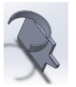
Figure 17B 3D printed thrust vector flap

idkwhatthisis16


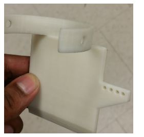
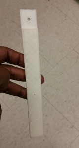
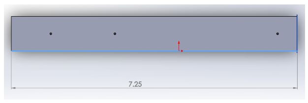
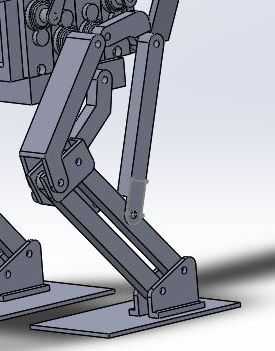
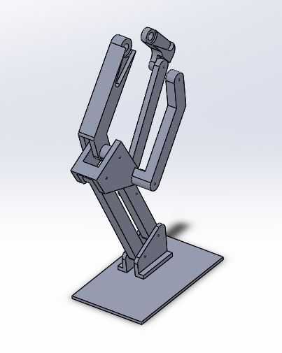
Lastly we noticed that if we were going to use all these attachments then we were going to have a problem with the legs since the attachments were long and were going to hit the floor. I modeled out new legs which were long enough so the attachments wouldn’t hit the ground when standing. These legs were approximately 7.25 inches long total but was given one inch clearance to mount them on to the vehicle (Figure 18). They were designed to be .2 inches thick so they would not break easily since it was supporting the weight of the vehicle. The fabricated part can be seen in Figure 19.

Figure 19 CAD of replacement legs                                  

idkwhatthisis17

Figure 19 3D printed replacement leg

leg

Though these attachments have been modeled and fabricated, we were not able to use any of them nor the servos simply because the added too much weight to the vehicle and made it too heavy to fly. Even adding on the servos alone made the vehicle too have so we could not use those however these concepts can be used for future semesters if they choose to go with a similar approach and taking account the weight ahead of time.

Spring 2016 Velociraptor: 3D Smoothing

By: Mingyu Seo (Manufacturing & Design)

Introduction:

In order to accommodate mass budget of the robot, our team has decided to create the legs and the top using 3D filament polylactic acid (PLA). One of the drawbacks of using 3D printing method is the result of the prints having ridged surface texture created by the layer by layer printing. There are multiple solutions for smoothing surface of PLA 3D prints to make the final product better. We will be looking at 2 methods that are safe and simple to apply.

3D printer setting:

Layer height (mm): 0.25

Shell thickness (mm): 1.2

Bottom/Top thickness (mm): 1.0

Fill Density (%): 25

(Leg Picture here)

The picture shows the one of the finished print for the right leg, which we could clearly see the ridged surface texture.

Smoothing Methods:

  1. Acetone Bath
  • Acetone bath is one of the most commonly used method to smooth out PLA and ABS materials. It melts the outer plastic and creates a smoother and glossy looking surface. Acetone bath is the simplest and fastest method to smoothing 3D materials.

Procedure:

  • (Optional) Sand the 3D material using sandpaper (P320 most optimal) to smooth out the ridged surface.
  • Pour enough acetone in a container (Just enough to fully submerge the part)
  • Keep the part submerged for 40 ~ 60 seconds
  • Take it out and dry.

(*CAUTION: make sure to use gloves when handling PLA due to melted plastic)

2.  XTC-3D epoxy

  • XTC-3D epoxy has lately been getting attention in 3D community which uses 2 liquids that are mixed together and then brushed onto 3D prints. Due to XTC-3D is a protective coating that does not melt plastic, so sanding all parts before applying is highly recommended.

Procedure:

  • sand all surfaces of the 3D parts using P320 or P600 sandpaper.
    • starting off with P600 may be a safer option,
  • Apply coating on to 3D parts using a brush.
  • Dry for minimum 4 hours.

XTC-3D coating works with all 3D materials as well as wood, plaster, fabric, cardboard, and paper. It’s easy to apply but takes a long time to dry. It takes minimum 4 hours and may need to be applied several times to have a unified smooth surface.


Conclusion:

To decrease production time, our team has decided to incorporate acetone bath to our final product. Program Level 1 Requirement 1 states the Velociraptor biped robot shall demonstrate its feasibility as a toy. To fulfill this requirement, acetone bath will not only help to smooth out the rigged surface but also improve the look of the final product.

Spring 2016 Velociraptor: Hardware &Simulation

By: Mingyu Seo (Manufacturing &Design)

Introduction:

The purpose of this blog is to show the feasibility of the design we’re going to incorporate in to our robot. Using Solidworks, we’ll be able to validate center of mass of the robot when we’re performing static walking. Also by using the simulation on Solidworks, it’ll show the basic motion of the robot walking. Following hardware design will explain the problems and solutions we’ve made to find the most suitable design of Velociraptor.

Requirements:

Project Level 1:

  1. Requirement 1 states the Velociraptor shall resemble a Tyrannosaurus class of dinosaurs as given in the objective.
  2. Requirement 2 states the word “biped” is defined as having two feet; therefore, the Velociraptor shall use two legs to move.
  3. Requirement 4 states the Velociraptor shall be able to statically walk on all surfaces of the course
  4. Requirement 5 states the Velociraptor shall be able to dynamically walk on flat surfaces of the course.

Project Level 2:

  1. Requirement 4 states to resemble a Tyrannosaurus class of dinosaurs, the chassis of the Velociraptor shall be cut out in hollow body parts to assemble a frame-like body structure in a material that is cost effective
  2. Requirement 6 states to maintain balance while performing static walking, a head and tail shall be implemented to the chassis of the Velociraptor

Overall, the design of the robot must resemble a Tyrannosaurus class dinosaur, that walks on two legs, and by incorporating the head and tail will help keeping the robot balanced when it’s performing static & dynamic walk by shifting the center of mass using the weight of the head and tail. New designs were incorporated in to our new design to accommodate mass, price, and power budget.

Hardware Design:

1.1

Figure 1. Final Design of Velociraptor (excluding sensors)


2 (2)

Figure 2. Exploited View of Velociraptor

First Design:

right leg

Figure 3. First design of the joint

Figure 3. shows the first design of the joint which incorporates the 3rd joint that was missing from the previous generation. The new design also incorporates a new design of the ankle where it’s connected with 2 parts rather than 1 that holds the leg and the foot, which helps the foot to stay parallel to the surface at all times.

Problem: when assembling the first design, we had few design problems

  1. The 3D printed parts were not sturdy
    1. Not strong enough to hold up the weight of the body
    2. putting too much pressure on the base of the foot started bending parts.

Second Design:

kinda new right leg

Figure 4. 2nd Design of the joint

Figure 4. incorporates the fixed design of our first design. We made all our parts minimum 0.3 cm thickness to prevent our parts from bending. The front joint that connects from front servo to the knee has thickness of 1.2 cm to have a more stable stance, and make sure it’s sturdy enough to hold the weight of the robot.

Problem:

  1. By increasing the thickness of the joints also increased the angle the head and tail must turn in order to shift the center of mass when performing static walk.
  2. When designing the 3D model, the design did not compensate the extra length added due to servo caps.
  3. The thickness of the foot was still too thin.

Final Design:

New right leg

Figure 5. Final Design of the joint

Figure 5. shows the finalized design of the leg of Velociraptor.

Final Features:

  1. Shifted the front top joint (connecting from front servo to the knee) to the out in order help the robot to find center of mass by moving the head and tail less.
  2. Also have incorporated the placement for the servo caps to bring it closer to the center.
  3. All parts have minimum 0.3 cm to have a stable stance when it’s performing static walking.
  4. Extra length toward the back and outer side of the foot to have a more stable and balanced walking.

PCB placement:

First when we were designing the robot, we have decided to place all the sensors and the pcb underneath the servos. After finishing our PCB layout, we have found the size of the board too big to be placed under and due to the size of the voltage regulator it was not applicable to fit all the components under the robot. In order to solve this problem, we have decided to create a clear casing on top of the robot and place all our components in.

Design Features:

  1. Bottom of the case have been cut out in order to bring the wires underneath and hide it.
  2. hole has been placed on the front side of the casing to place the ultrasonic sensor.
  3. casing will be made with a clear PLA filament to show the components inside.
pcb placement

pcb placement2 Figure 1. Design of the casing to hold up the PCB and also the top view of the casing


Simulation:

The simulation below shows the motion of the Velociraptor when it’s performing static walking.

In order to balance on one foot, we need  to move the center of mass above the supporting leg by moving the head and tail toward the supporting leg for counter weight.

ezgif.com-video-to-gif

Conclusion:

This simulation shows the given dimension of the 3D model shows the feasibility of the design of the Velociraptor, and confirms the level 1 requirement 4, which states the Velociraptor being able to statically walk across the full course. The design that we have incorporated have been tested and resulted as successful when we’ve performed static walking. Biggest issue was trying to keep all wires and components hidden but due to the size of the PCB and the size of the voltage regulator heatsink we have decided to mount it on the top of the robot. The Head, Tail, and bottom plate for the robot was made with Aluminum, but the legs, top plate, and the PCB casing will be printed using PLA filament.

Spring 2016: 3DoT David Blog Posts Table Of Content

BY: Omar Mouline ( Project Manager)

Project Manager (Omar Mouline)

  1. Spider-Bot Preliminary Research Project.
  2. Spider-Bot Preliminary Design Document.
  3.  Spider-Bot Mechanism Research: When we design was assigned to us i did a little research on other mechanism to better understand the leg movement.
  4.  Blog Posts Table Of Content: All the blog posts link with a summary to faster access information.
  5. CDR Debrief: After the CDR we were given the grades and asked to
  6. Executive summary: Project objective, mission profile, and design change arguments

Electronics and Control Engineer (Kent Hayes )

  1. Spider-Bot Preliminary Research Project.
  2. Spider-Bot Preliminary Design Document.
  3. Servos and Motor Trade-off Study: Research and trade-off studies on different motors servos to make sure we made the right decision.
  4. IR Emitter/Detector Testing: Fritzing and connection of the IR system and test.
  5. IR Lens Study: since the IR emitter have a big range we had to use a lens to reduce the range of the IR emitter.
  6. PCB Design: PCB design for our Project.
  7. Motor Driver Control: we needed a motor control drive to control our motors.
  8. IR Trade-Off Study : trade of studies on different IR emitter detectors possibilities.
Missions, Systems and Test Engineer (Christopher Hirunthanakorn)
  1. 3DoT Board Troubleshooting: Installing software and testing and verification.
  2. Spider-Bot IR Transmitter and Receiver Research:  Research on how the IR transmitter detector work.
  3. Arxterra Firmware Configuration: Firmware how to connect the 3DoT board to an iPhone or Android

Manufacturing and Design Engineer  (Andrew Saprid )

  1. Spider-Bot Preliminary Research Project.
  2. Spider-Bot Preliminary Design Document
  3. Spider-Bot Alternative Printing for Small Parts: Research Made on different possibility on how to manufacture our design.
  4. Spider-Bot Cam Simulation: simulation of the first (Hex bug) Cam design.
  5. Gear Instability : we were able to find 2 type of gears on Amazon we test and tried both.
  6. Rapid Joint Connection (Between Gear and Leg): As part of the adjustment we had to do to the new design , we had to add a joint to our design.
  7. Simulation and New Design Parts simulation of the final design movement.
  8. Printing Time: The printing time show the options we have to respect our printing requirement.
  9. Gear Train: study and what RPM we need to receive 2 cycle per second.
  10. Leg Movement Angle Study: What angle we need so our spider legs can give us a correct walk.
  11. Design Evolution: how Brainstorming helped to improve our designs.

Spring 2016 RoFi: Feet Material Verification Test

Christopher Andelin (Project Manager)

Mario Ramirez (Systems Engineer)

Qui Du (Manufacturing Engineer)

Andrew Laqui (Electronics and Controls Engineer)

Henry Ruff (Electronics and Controls Engineer)

Table of Contents

Feet Material Verification Test

Mario Ramirez (Systems Engineer)

Requirement

Nonslip material on the bottom of RoFi’s feet shall have a friction coefficient of 0.9 +/- 0.05.

Test Objective

To verify that the material on the bottom of RoFi’s feet has a friction coefficient of 0.9 +/- 0.05 with a laminated podium.

Tools

Figure 1 shows the tools I used to calculate the friction coefficient of RoFi’s shoes.

figure 1

Figure 1: Tools

Preliminary Calculations

Figure 2 indicates the vectors involved in my experiment.

figure 2

Figure 2: Incline Vectors  http://i.stack.imgur.com/lMCD8.png

μ = friction coefficient

Equation threshold where static object begins to move: m*g*sin(theta) = μ*m*g*cos(theta)

Procedure

Step 1: Weigh desired mass and attach non-slip material.


figure 3_compressed

Figure 3: Mouse Pad Attached to Mass

Step 2: Place mass and material on an incline.

figure 4_compressed

Figure 4: Starting Location and Angle

Step 3: Tilt surface until slipping occurs and record the angle.

figure 5_compressed

Figure 5: Mass Slipped

Step 4: Calculate friction coefficient using equation.

Results

A second material was tested along side the mouse pad to show a difference in friction coefficients.

figure 6

Figure 6: HD Non-Slip Pad

figure 7

Figure 7: Mouse Pad

Reference

http://www.physicsclassroom.com/class/newtlaws/Lesson-2/Types-of-Forces

http://physics.stackexchange.com/questions/243717/why-does-something-on-an-inclined-plane-move-forward-at-all

Spring 2016 RoFi: Verification Test Plan

Christopher Andelin (Project Manager)

Mario Ramirez (Systems Engineer)

Qui Du (Manufacturing Engineer)

Andrew Laqui (Electronics and Controls Engineer)

Henry Ruff (Electronics and Controls Engineer)

Table of Contents

Verification Test Plan

Mario Ramirez (Systems Engineer)

Purpose

To verify requirements based on the verification matrix.

Requirements

  • RoFi shall remain balanced over an inclined surface of  up to 8 degrees and a threshold of up to 45 degrees.
  • The ultrasonics sensor shall detect an object within 3-400cm and begin an avoid obstacle subroutine.
  • Nonslip material, on the bottom of RoFi’s feet, shall have a friction coefficient greater than 0.9.
  • The Bluetooth module shall be a power class 2 Bluetooth module which gives a range of 10 feet between the module and the cell phone.
  • Servos shall supply a minimum torque of 288kg*cm to move a mass of 862g.
  • The periscope attached to the cell phone shall have a lens size of 1.8 * 1.8 * 2.2cm and give a 90 degree view from the cell phone camera.

Matrix

Figure 1A and Figure 1B is the verification matrix.

figure 1a

Figure 1A: Verification Matrix

figure 1b

Figure 1B: Verification Matrix

Tests

Incline

Figure 2 is a table of the tools needed for determining the angle of an inclined surface.

figure 2

Figure 2: Tools used for Incline

To conduct this test, I can either locate surfaces at varying angles or I can construct a ramp and put things underneath to adjust the angle from 0 to 30 degrees.

Steps:

  1. Measure angle of desired surface.
  2. Command RoFi to walk up the surface.
  3. Gather information from the Arduino IDE serial Monitor and compare to measured results.

Detection

Figure 3 is a table of the tools needed for testing the ultrasonic sensor.

figure 3

Figure 3: Tools used for Ultrasonic Sensor

The measuring tape will be used to verify that the results the serial monitor is displaying is accurate and that the sensor can detect objects within its given range.

Steps:

  1. Setup ultrasonic sensor circuit and code.
  2. Place the measuring tape alongside the ultrasonic sensor.
  3. Starting at about 400 cm away from the ultrasonic sensor, move an object at 5 cm increments.
  4. As object is moved, compare the serial monitor and the measured values.

Feet Material

Figure 4 is a table of the tools needed for calculating the friction coefficient of RoFi’s shoes.

figure 4

Figure 4: Tools used for Calculating Friction Coefficient

Equation:

  1. Ff = force of friction
  2. μ = friction coefficient
  3. F f = μ *m *g *c o s( α)

Steps:

  1. Place material that is to be measured on an adjustable ramp.
  2. Place mass on the material to be measured and angle the ramp until it begins to slide down the ramp.
  3. Calculate the force needed to move this material down the slope.
  4. Verify that the force of RoFi’s step is less than the force needed to make the material slip.

Bluetooth Module

Figure 5 is a table of the tools needed for testing the Bluetooth module.

figure 5

Figure 5: Tools used for Testing Bluetooth

Setup the Bluetooth module with the Arduino and a simple LED for testing.  Insure your code is uploaded to the Arduino and begin.

Steps:

  1. Lay out the measuring tape to read between 1 to 10 feet.
  2. Starting from 1 foot, turn the LED on and off to insure you are connected.
  3. Move away 0.5 feet and again turn the LED on and off to insure you are connected.
  4. Repeat step 3 until you reach 10 feet.

Servos

Figure 6 is a table of the tools needed for testing the servo torque.

figure 6

Figure 6: Tools used for Testing Servo Torque

https://www.arxterra.com/spring-2016-rofi-torque-report/

Weigh out a mass of 900g,  we are using 900 grams because it is easier to obtain this value and if the servo can move 900g it can move 862g.  Connect a resistor of 1 ohm or less in series to the ground of the servo.  Connect the oscilloscope to measure the voltage over the resistor. Use V/R=I to obtain the current the servo is drawing.

Steps:

  1. Mount the servo on the edge of a table.
  2. Connect the mass to the servo with twine or rope.
  3. As the mass is moving, calculate your current drawn to insure that it is below your stalling current.

Periscope

To verify that the periscope provides a 90 degree view relative to the camera.

Figure 7: Tools used for Testing Periscope

Steps:

  1. Attach periscope to the cellphone camera.
  2. Take photos and/or video.
  3. Connect to Arxterra control panel and verify vision.

Spring 2016 A-TeChToP Seizure Watch Sensor Testing

By Rose Leidenfrost (Electronics and Control Engineer)

Overview

This blog post provides an outline of experiments used to test the functionality of the sensors used for the wrist worn device. Results conclude the feasibility of the sensor data to be used for seizure detection.

Read more

Spring 2016: 3DoT David Executive summary (Design Change Arguments)

BY:

Omar Mouline                                    ( Project Manager),

Christopher Hirunthanakorn          (Missions, Systems and Test Engineer)

Table of Contents

Project objectives:

The objective of 3DOT David Spider is to use scaled model of the Hexbug prototype to produce a cool project for the DIY community. The preferred method of control is to use Bluetooth communication between the remote-control (Iphone or Android) and the microcontroller on board of the spider The finished product must meet the following Program and Project Requirements:

  • System processing using a microcontroller (either the 3DoT Board or Sparcs Macro.)
  • Total production cost must not exceed $80.00.
  • Short 3D Printing ( Not exceeding 6 hours and less than 2 hours for each single print)
  • Control The Spider Bot from Arxterra app ( Android or Iphone) using bluetooth
  • 3Dot david must be able to perform a safe interactive game with other projects in a specific field and date as Defined in mission profile

Mission Profile

The Mission Profile for the 3DoT projects is to perform robotic combat. With regards to the College of Engineering Health & Safety Policy, the projects must meet the following Requirements:

  • The game will take place in ECS 315 in a 6 x 6 ft. area on the linoleum floor.
  • Go head to head with other robots in an indoor game of IR tag
  • The emitter must hit the detector in a straight line from a maximum distance of 5 ft.
  • Every time a player is “tagged” by the IR tagging system, a sound will go off
  • Delay time after each tag shall be 5 seconds
  • When either robot has been “tagged” 3 times, the bot will shut down, indicating the game is over.
  • The entire game will last from 10-15 mins

Updated requirements:

Program requirement:

  1. As a senior design project for Spring 2016, the project shall be completed by May 13th, 2016 Monday, May 9, 2016 2:45PM – 4:45PM (Final day) on the linoleum floor of ECS315 at CSULB.http://web.csulb.edu/depts/enrollment/registration/final_exam/spring_chart.html
  2. As a senior design project for Spring 2016, Documentation of the 3Dot Spider-bot shall be completed by the 25th of April http://web.csulb.edu/~hill/ee400d/Syllabus.pdf

Project Requirement:

  1. The 3DoT David shall be a robot that demonstrates the capability of the new 3DoT micro-controller for DIY hobbyists.
  2. The 3DoT David shall be a low cost project with a total cost that does not exceed $79.95, which includes the cost for 3D printing, PCB, battery, and other components.
  3. To document the difference between development cost and final product cost, the 3DoT spider project must create a Project Budget and a Product Budget.
  4. The 3DoT David shall be controlled by the Arxterra App used on a smartphone.
  5. The 3DoT David shall incorporate 3D printed parts to demonstrate the feasibility of the 3DoT board for 3D printed robots.
  6. The 3DoT David shall have a maximum 3D printing time of six hours for production of parts to ensure the quick production of the robot. Any single print cannot exceed 2 hours.
  7. The 3DoT David shall compete with other robots in a game of tag to demonstrate the functionality of the robot. The basic rules of the game are using an IR emitter to tag the opposing robot, must compete in a 6×6 ft area, have a delay period of 5 seconds after each tag, and be disabled for 10 seconds after three tags.

System requirements:

  1. The 3DoT David shall utilize the HC-06 Bluetooth module on the 3DoT board in order to receive commands from the Arxterra App using a smartphone.
  2. The 3DoT David shall use a single 3.7V Lithium-ion battery or a 3.7V Lithium-ion Polymer (LIPO) battery to provide power for the robot. The 3DoT board will be providing power to all of the peripherals and uses a 3.7 Lithium-ion battery as its power source.
  3. The 3DoT David shall use two micro motors for the movement system of the robot.
  4. The 3DoT David shall use an infrared LED emitter and infrared detector for the tagging system in the game of tag.
  5. The 3DoT David shall be disabled for 10 seconds after being tagged three times to signify the end of a round in the game of tag. This means the robot does not respond to any commands for 10 seconds.
  6. The 3DoT David shall operate for 10 to 15 minutes, which should be equivalent to three rounds of the game of tag.
  7. The 3DoT David shall use a small speaker to produce the buzzing sounds to indicate the end of a round in the game of tag.
  8. The 3DoT David shall use a 3D printed chassis and legs. This follows from the project level requirement about using 3D printed parts.
  9. The 3DoT David shall include a PCB that uses a Schmitt Trigger circuit to convert the analog output from the IR detector into a digital output to be handled by the 3DoT board. It will also have a voltage follower and anti-aliasing filter for the synchronization of the two motors. This PCB shall also provide the connections from the 3DoT board to the peripherals such as the IR emitter, IR detector, and micro motors.

Subsystem requirements:

  1. The micro motors shall operate in between the supply voltage of 3.7V-5.0V, be able to rotate 360 degrees continuously, have a stall current of no more than 250 mA, and cost no more than $10 each in order to stay within our budget.
  2. The 3DoT David shall be made from PLA or ABS filament in order to minimize the mass of the robot and be strong enough to hold its weight.
  3. The IR emitter and IR detector shall be positioned at least 3 inches from the bottom of the 3DoT David.
  4. The maximum distance for the IR detector to detect a direct hit shall be 5 ft. This threshold is for when the IR emitter of the other robot is directly aligned with the IR detector, not when it is at an angle.
  5. The spider-bot shall have six legs to operate its course to battle robots.

Project key features 

Design Change

We have been working nine weeks to design the the Hex bug in Solid Work, in week 9 our team with the agreement of the customer decided to Change the design for these reasons:

The hex bug design:

  1. Had a lot of small parts that needed to be printed with precision
  2. It was very complex for a beginner in solid work to design without a professional formation and the right help.
  3. 3D print resource provided couldn’t print our small parts with the precision we needed.
  4. All the part for the design needed to be 3D printed which will be impossible to accomplish with the time restriction given by the costumer.
  5. We couldn’t use any option other than 3D printing to fit our budget.

The geared design:

  1. We were able to be creative and adjust the design to our needs.
  2. The gear movement need some adjustment since the prototype walked only straight. we added a motor to control each side of legs.
  3. By adding the motor we were able to compile the moment of the spider. When we turn off the right motor the spider turn right and vice versa.
  4. Less part to print and they all were able to print with precision
  5. We could of used different method like laser cutting to get some parts but the 3D printing time was enough for our requirements.
  6. The Solid work design level of complexity was little bit higher than the formation and help provided by the division for the manufacturing engineer but not as high as the level of complexity of the Hex bug design.

Tagging System (interactive game)

For the interactive game we had 3 options : Laser tag, IR tag, and Ultrasonic. After doing research on each option we settled with IR tagging system for its safety. in the pictures below show some arguments why we choose the IR:

Screen Shot 2016-05-06 at 1.02.16 PM

Motor Control

After assembling the 3DoT David we found that the Motor synchronization is optional, the leg position helped the robot to move forward even if the motors are not in sync. Before that, we looked different possibilities on how to synchronize the two motors and it is shown on the table below:

Screen Shot 2016-05-06 at 1.05.15 PM

We ended up choosing the Flex resistor. After implementing it to our robot we found that there is a different where the spider move was more in sync.


Spring 2016: 3DoT David IR Lens Study

By:  Kent Hayes (Electronics and Control)

Introduction:

The way we currently have our set up for the IR emitter/detector, the maximum range is about 3in. In order to meet this requirement, Kent researched and found a way to drastically increase the range by incorporating a lens. Kent previously purchased 11.3mm lenses for our IR emitters. He chose this size for the diameter based on the limited space with which we have to work. We were thinking of creating a tube and mounting it on the side of the PCB box (3in x 2in) that we were going to print. However, there was a change in the design of the legs which pushed our printing time over the 6hr limit so we will not be using the box, and will therefore be mounting it somewhere on the top plate.

Related requirements:

The subsystem requirement states the following:

  • The maximum distance for the IR detector to detect a direct hit shall be 5 ft. This threshold is for when the IR emitter of the other robot is directly aligned with the IR detector, not when it is at an angle.

Lens options:

There are various types of lenses of which to choose from such as convex, concave, spherical, and compound.

  •         Convex: causes light rays to converge/concentrate into one spot
  •         Concave: causes light rays to diverge/spread out
  •         Spherical: less focused the wider the beam angle
  •         Compound: Increasing the focus while decreasing image distortion(aberration)

The lens that will work the best for our project is the convex lens since I wish to focus the IR beam as narrow as possible while increasing the range. There are different types of convex lenses as well. Among these are the more popular plano-convex and asymmetric double convex lenses because they produce the least amount of aberration. There is no notable difference between the two for this application, so I purchased the plano-convex.

IR_LensCalculations_LensChoicesI did further research online in order to preform calculations that would work with the measurements I do have thus far. The following image is of calculations I found on the magnification (M) in relation to the distance projected from the lens to a wall (dScreen)and the distance from the LED to the lens (dLED).

IR_LensCalculations_FL_M_dLED

I followed the formula to calculate the magnification factor with the following values:

DScreen = 2m (Requirement for the IR emitter to be able to fire from 2m away)

DLED = 5mm (Random number just to do calculations)

With these I calculated the mag factor

M = 2000mm/5mm

M = 400

With the mag factor, I can then calculate the focal length of the tube.

Flens = 2000mm/(400+1)

Flens = 4.98mm

I also tried using a larger value for DLED to see what would happen to the focal length

M = 2000mm/10mm

M = 200

Flens = 2000mm/(200+1)

FLens = 9.95mm

These results suggest that my focal length should be between 5mm and 10mm.

In order to get an exact value for the focal length, I did further research and found a helpful link that dealt with the focal length as well as the diameter of the lens. The following Image is of what I found:

IR_LensCalculations_Diameter
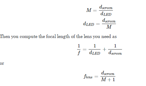
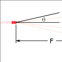
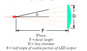
On the webpage I found this picture, it listed a formula for determining the minimum lens diameter. It is as follows:

D = 11.3mm lens diameter

F = focal length

Θ = 40 (half angle intensity of the current emitter we are using)

D > 2*F*tan(Θ)

11.3mm > 2 * F * tan(40)

F < 6.73 mm


Conclusion:

From the calculations made, we will be making a lens tube with a focal length less than 6.73mm with 11.3mm in diameter. In order to determine your focal length, you will need to use the half angle intensity of your own emitter and the diameter of the lense you have bought.

Resources:

Diameter/Focul Length Calculations | http://alumnus.caltech.edu/~leif/infratag/lens_choice.html

Magnification Calculationshttp://physics.stackexchange.com/questions/146956/how-to-chose-right-lens-for-concentrating-ir-signal

Types of Lenses Summary | http://micro.magnet.fsu.edu/optics/lightandcolor/lenses.html