
Goliath Fall 2017 – Final Budget and Expenses
This post is in accordance with the project requirement L1.11, “Budget”. In comparison to both the total expected cost and actual cost column, we could see which resources were supplied, cut, or purchased.A good portion of the components was covered through the use of previous semesters’ components specifically the: motor, 3dot board, and battery. The […]


Goliath Fall 2017 – Goliath Arduino Code & Calibration
The purpose of this post is to link to the final Goliath code and explain the overall structure for future use. Secondly, to explain how the code needs to be updated and calibrated to a particular Goliath chassis. Overall, getting the Goliath code to work for this mission involved the creation of 16 files and over […]
Fall 2017: ModWheels Final Project Document
By: Lucas Gutierrez (Project Manager)
Table of Contents
Project Overview
Team
Fall 2017 ModWheels:
Project Manager: Lucas Gutierrez
Mission, Systems, & Test Engineer: Andrew Yi
Electronics & Control Engineer: Matt Shellhammer
Design & Manufacturing Engineer: Natalie Arevalo
Summary
The Fall 2017 ModWheels toy car is a new project within The Robot Company. Its modular design comes from the changeable paper overlay, allowing the user to swap out to their preferred design. To control the robot, a 3DoT micro-controller is used to connect the user to the robot via Arxterra, a platform for easy robotics integration. A sensor suite will enable this to navigate a 2D maze, as defined by the customer. Infrared sensors gives ModWheels the feature of line of the maze, keeping the toy car within the confines of the maze hallways. To avoid collision, a proximity sensor gives ModWheels the ability to detect the other robots, which allow for the robot to avoid collision within the maze.
Mission Objective for Fall 2017
ModWheels is a toy car that will navigate a multi-colored 2D maze using autonomous capabilities as well as Arxterra to guide the toy car through the maze. The initial phase consists of having the toy car navigate the maze with user input, to which ModWheels will then memorize the route taken during the initial phase and will be able to autonomously navigate the maze for the second phase, all while being able to detect other robots and avoid collision. These are the mission objectives stated by the customer.
System Design
ModWheels is sized to fit the maze as defined by the customer for the Fall 2017 EE 400D semester. This final document will detail the mechanical design, electronics and control, and sensor suite that made ModWheels the project that it is.

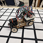
Figure 1: Fall 2017 ModWheels Prototype Used for Final Mission
Subsystem Design
Modeling Results
The use of SolidWorks helped to the ModWheels project design and model the chassis, steering mechanisms, and holders implemented onto the toy car. Tire treads were designed, modeled, and provided by Jeff Gomes.
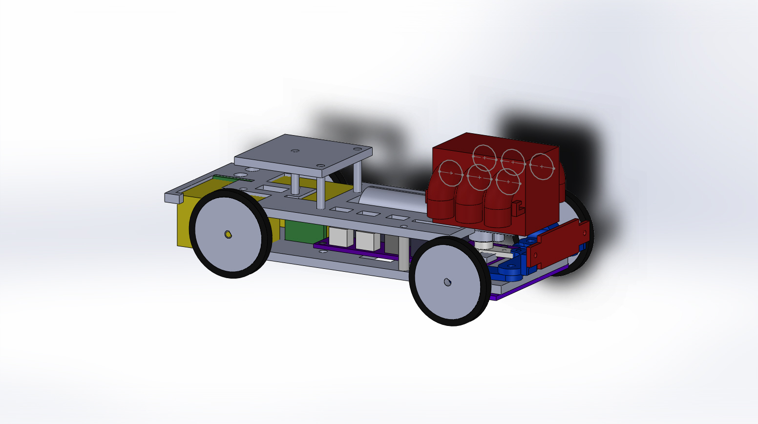
Figure 2: Fall 2017 ModWheels 3D Model
Interface Definition
To help satisfy customer requirements, a system block diagram defines the capabilities of the ModWheels electronics and control. The interface matrix also verifies that the system block diagram and actual implementation of the ModWheels go hand in hand.
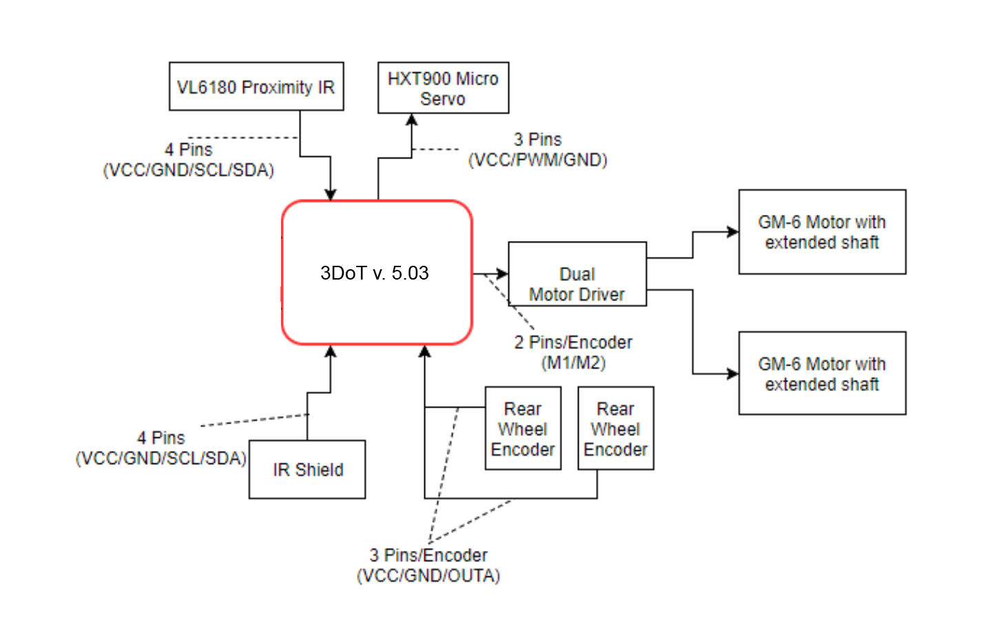
Figure 3: Fall 2017 ModWheels System Block Diagram for 3DoT v. 5.03

Figure 4: Fall 2017 ModWheels System Block Diagram for Pro Micro
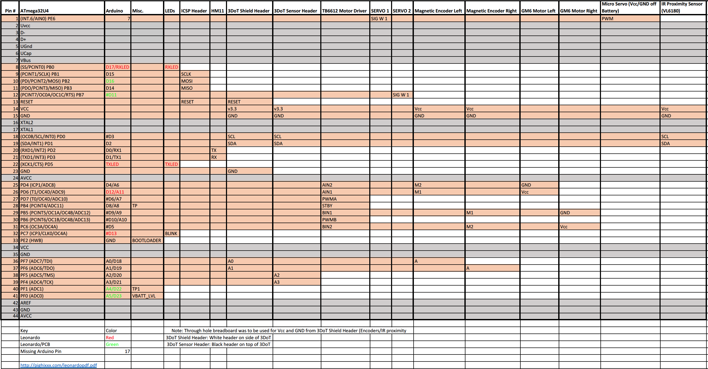
Figure 5: Fall 2017 ModWheels Interface Matrix
Mission Command and Control
An important aspect in fulfilling ModWheel’s mission requirements is integration with the Arxterra platform, both with the phone application and web based application. To tailor and customize the user experience of the Arxterra applications to the ModWheels project, a few custom commands and telemetry will be incorporated. ModWheels would have implemented a 4 state custom command on the Arxterra GUI.
Electronics Design
In the design phase, ModWheels was design to electronically and mechanically adapt to the v. 5.03 3DoT, which was to be provided by the EE 400D . Due to complications with the fabricated 3DoT v5.03 and the limited amount of time we were required to resort to the use of the Sparkfun pro micro and motor driver for the final implementation.
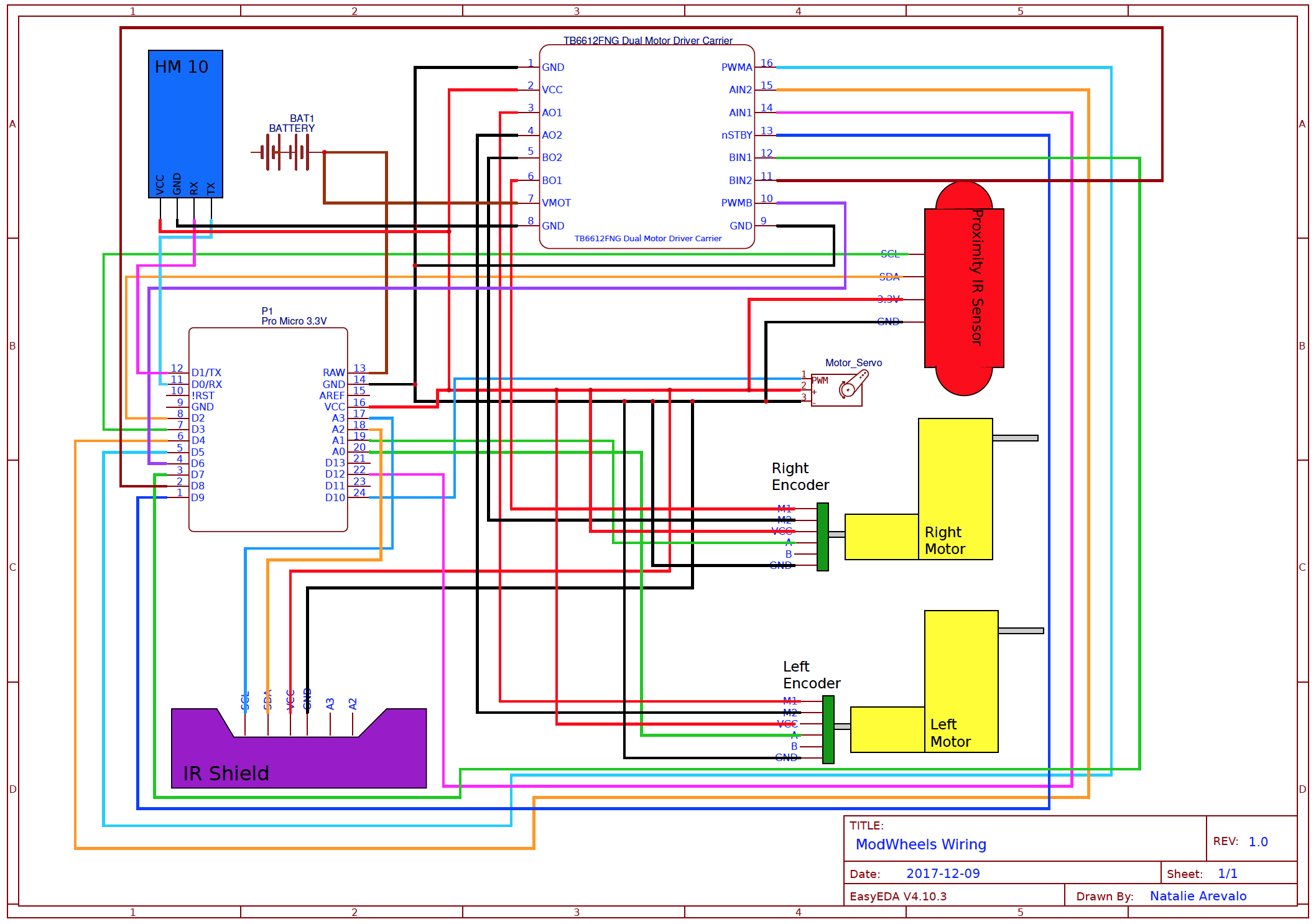 Figure 6: ModWheels Cable Diagram for Pro Micro (Used on mission)
Firmware
The software is one of the most important factors within the ModWheels project for maze navigation. With the help of Matt Shellhammer (Electronics & Control Engineer for ModWheels), an adaptation for maze navigation from EE 444 to EE 400D was made. Since the 3DoT was not used on the mission due to complications, a more simplified code was implemented on the prototyping board.
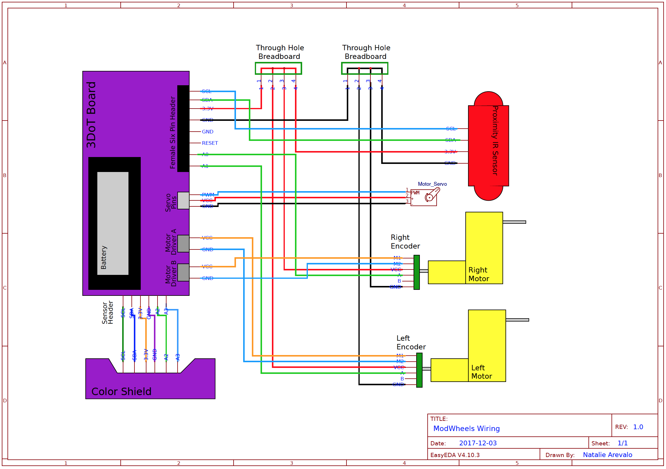
PCB Schematic & Layout
Among the requirements set by the customer, all projects must design and fabricate a custom PCB. However, due to the nature of our project and its design, a custom PCB is not necessary. In order to get the requirement of the custom PCB waived, a cable diagram for our project was provided. The description and diagram show that the components within our design can be directly connected into the 3Dot board without being interfaced through a custom PCB.
Hardware Design
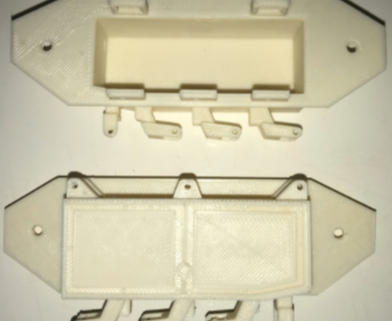
The ModWheels toy robot implements a blend between 3D printed components, as well as laser cut wood. This blend of materials helps to optimize cost and time (wood being inexpensive and quickly cut by a laser cutter) while keeping functionality (3D printed steering mechanism and engine block to hold the servo).
Figure 8: ModWheels Fall 2017 Prototype used on mission
Verification & Validation Test Overview/Summary
To confirm implementation of requirements, verification and validation of requirements of the ModWheels project was performed. To perform verification and validation of the requirements, a verification list and a validation test procedure was created.
Project Status
Power Allocation
As requested from the customer, the ModWheels will be implementing the 3DoT micro-controller. Due to the nature of the 3DoT, power restrictions must be made to ensure proper operation and performance. The power budget not only gives a worst case scenario of power consumption, but also helps to provide numbers to calculate mission duration, a very important factor to mission success.
3D Print Times
As set by the customer, there is a limit on the time allotted for the parts that will be 3D printed for the robots. The rule for 3D printing is that total print time must not exceed six hours, with no single part taking more than two hours to print. Once the 3D models were finalized and sent to be printed, a full rundown of labor, time, and cost were provided, which gives ModWheels final print time results.
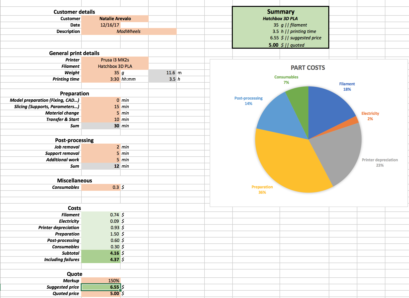
Figure 9: Final print time summary
Cost Report
As part of the requirements stated by the customer, a budget was set for the ModWheels project for no more than $200.00 . To help cut some costs, the EE 400D previous semester’s inventory of electronics, hardware, and materials were provided for use. The Budget report includes total cost of the project as well as cost of the project offset by inventory.
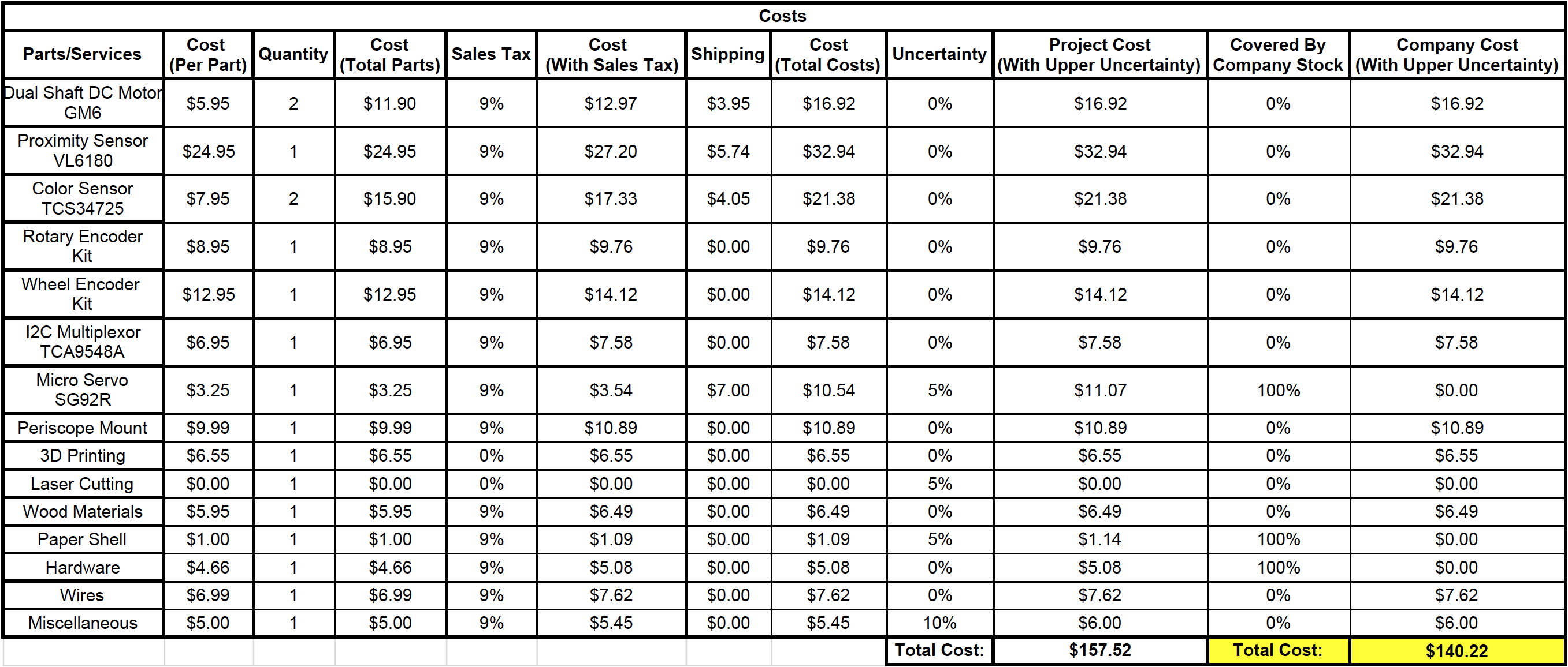
Figure 10: Fall 2017 ModWheels Budget
Schedule
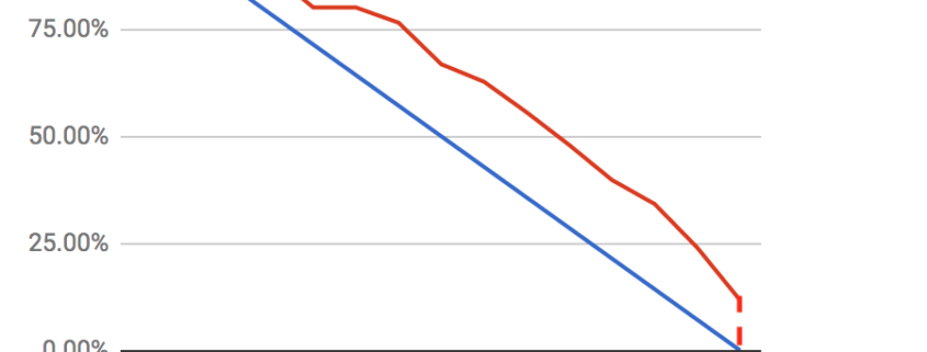
To help keep ModWheels on schedule, a project plan was created. The project planning along with the project burndown helps to give an estimation to work performed and work needed to complete the project.

Figure 11: Fall 2017 ModWheels Top Level Schedule
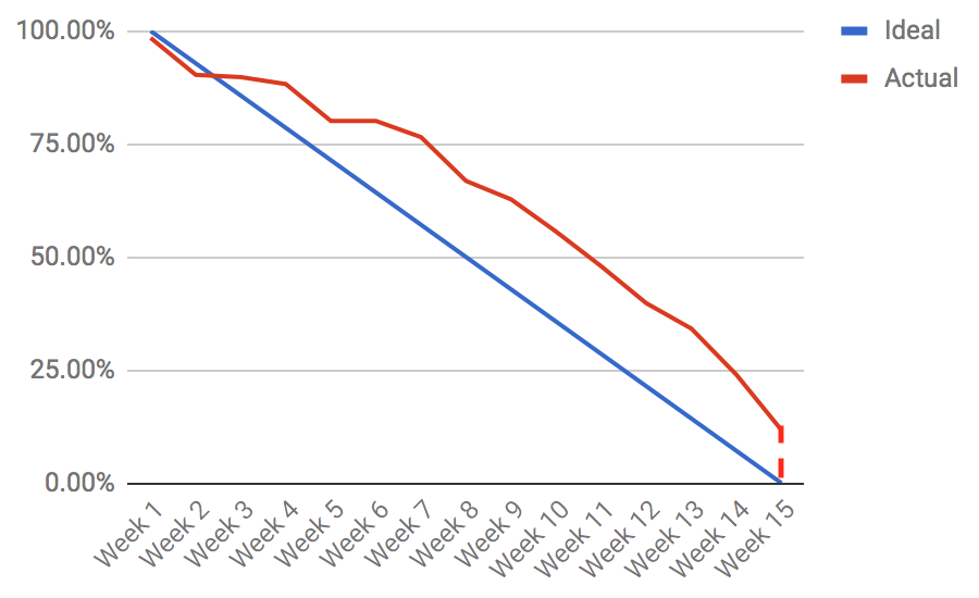
Figure 12: Fall 2017 ModWheels Project Burndown
Future Work
As the Fall 2017 semester concludes, a list of tasks have been compiled for following semesters to help further the ModWheels project and improve the 400D class.
- Fix IR shield to get improved readings and improve line following (change resistor values and refabricate as well as narrowing the distance between inside IR sensors to improve line following).
- Implement 3DoT v5.03 within ModWheels.
- Improved Steering
- Improve steering mechanism on ModWheels chassis to improve steadiness of steering.
- Change screws holding steering mechanism together to clamps or something that locks together so they steering mechanism won’t unscrew as it moves and turns (similar to what holds the 3DoT into place on the ModWheels chassis).
- Reduce size of servo holder to have a tight fit for the servo so it won’t move as it tries to move the steering mechanism.
- Improve software to implement Arxterra control of the robot (implement and test software developed for 3DoT v5.03 ModWheels after v5.03 is fixed).
- Improve power budget (more testing with servo to determine current draw and effectiveness at different supply voltages).
- Design modifications to allow for software upload while 3DoT is in the ModWheels chassis.
Fall 2017: ModWheels Schedule
By: Lucas Gutierrez (Project Manager)
Discussion
To help keep ModWheels on schedule, a project plan was created. The project planning along with the project burndown helps to give an estimation to work performed and work needed to complete the project.
Schedule
Figure 1: Fall 2017 ModWheels Schedule
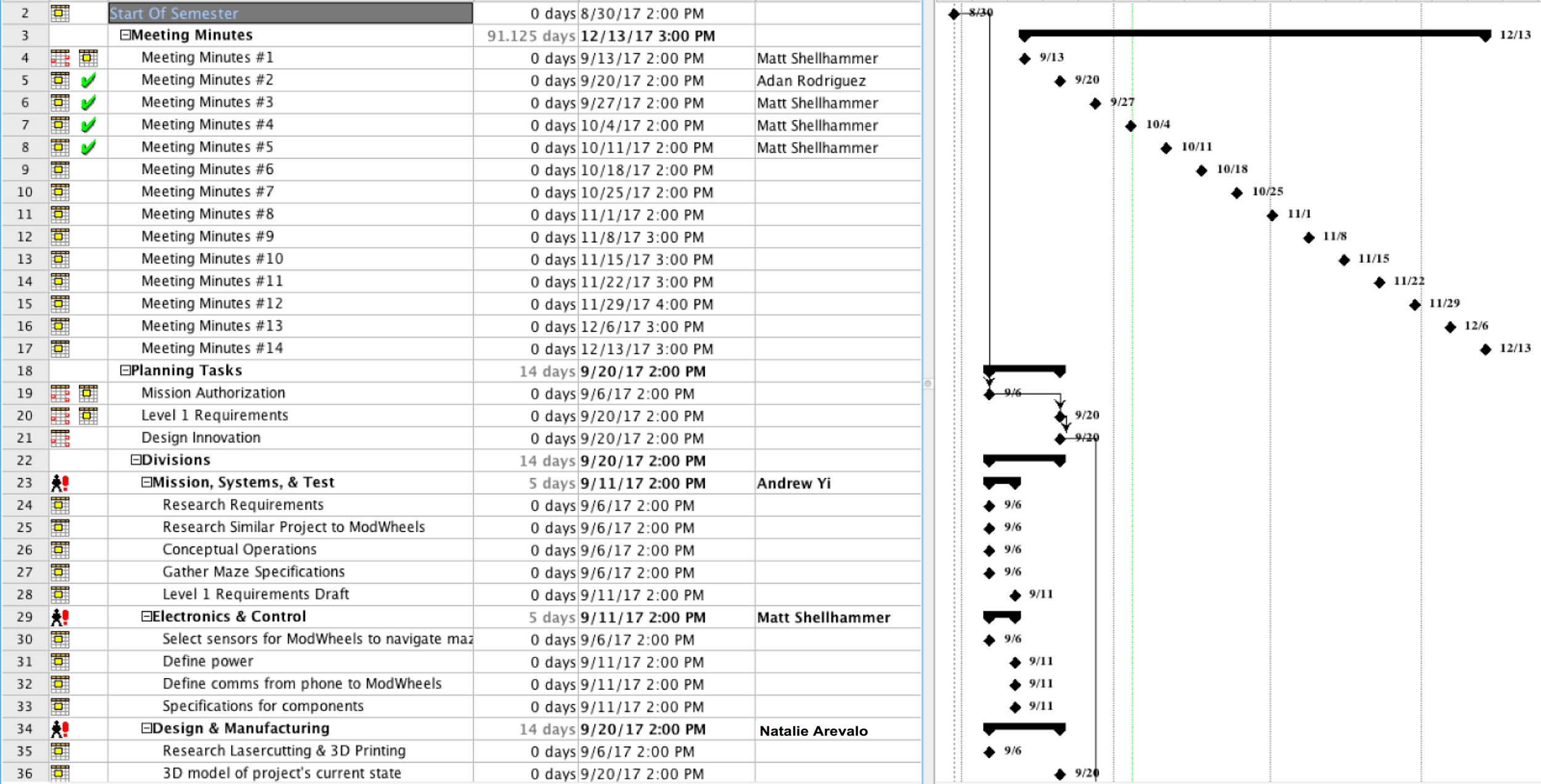
Figure 2: Fall 2017 ModWheels Planning

Figure 3: Fall 2017 ModWheels Design (1 of 2)

Figure 4: Fall 2017 ModWheels Design (2 of 2)
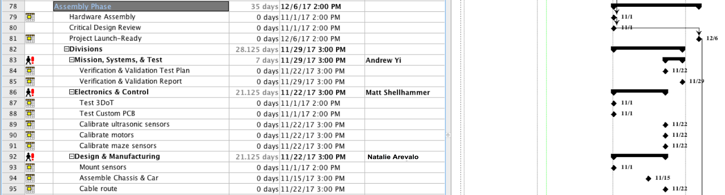
Figure 5: Fall 2017 ModWheels Assembly
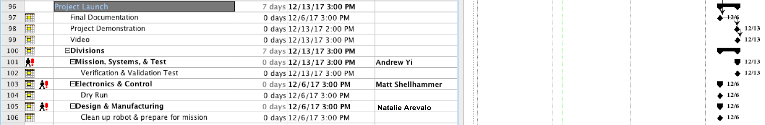
Figure 6: Fall 2017 ModWheels Launch
Figure 7: Fall 2017 ModWheels Project Burndown
Fall 2017: Interface Definitions
By: Andrew Yi (Mission, System, & Test Engineer) & Matt Shellhammer (Electronics & Control Engineer)
Approved by: Lucas Gutierrez (Project Manager)
Discussion
An important factor to operating the ModWheels project is linked to the connectivity of the micro controller and the sensor suite on the ModWheels chassis.
System Block Diagram
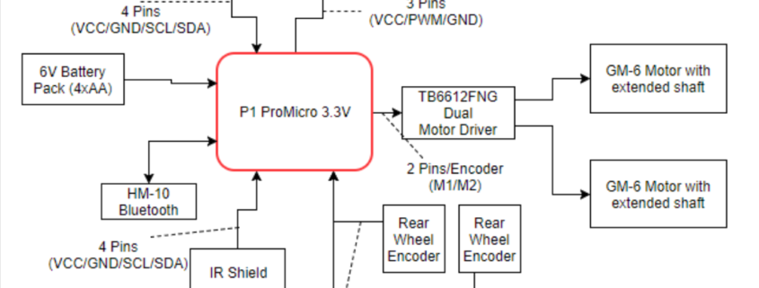
Due to unforeseen circumstances outside of our control, ModWheels was unable to implement a v. 5.03 3DoT micro controller. Instead, the board used for prototyping was used, the SparkFun Pro Micro. The ProMicro microcontroller replaced the 3DoT, but uses the same chip (ATMEGA 32u4). 3DoT implementation should be simple because of the similarities of the 2 microcontrollers. The encoders are connected via analog, sending data to the microcontroller, which then transmits data to the motor driver. 1.5V AA batteries power the toy robot via breadboard connections.
Figure 1: 3DoT v. 5.03 System Block Diagram
Figure 2: Pro Micro System Block Diagram
Interface Matrix
In this interface matrix we show how all peripheral electrical components will be connected to the 3DoT v5.03. ModWheels has a total of six peripheral devices, these devices are a micro servo, two magnetic encoders, two extended shaft GM6 motors, and a IR proximity sensor. These were all to be connected to the 3DoT without a PCB, however instead we were going to use a through hole breadboard to solder headers onto and create more Vcc and GND connections. With this in mind no PCB was required and all peripheral devices have a connection to the 3DoT with extra space for two more analog inputs. Only one channel of the quadrature magnetic encoders were used since the resolution was fine enough to make turns however if there was ever a need to include the second channel for the encoders there is still the remaining two analog connections on the sensor header.
Figure 3: Interface Matrix

Fall 2017: ModWheels Verification & Validation
By: Andrew Yi (Mission, Systems, & Test Engineer)
Approved by: Lucas Gutierrez (Project Manager)
Introduction
To confirm implementation of requirements, verification and validation of requirements of the ModWheels must be performed. To perform verification and validation of the requirements, a verification list and a validation test procedure was created.
Verification & Validation
ModWheels Verification & Validation Plan
Verification & Validation: List & Test Procedures
ModWheels Verification & Validation: List & Test Procedures

Eagle CAD Training
Written By: Muhannad Al Mohamed (E&C DM)
Table of Contents
Objective
This blog is intended to introduce Eagle CAD designing application to members to be able to design schematics for electronic circuits. The members of the E&C division are required to know how to make schematics of customed printed circuit boards (PCB) for their corresponding projects. These schematics can be used to design the layout version of the PCB in the Eagle CAD layout part. The layout of the PCB can then be used to generate Gerber files; which can be sent to fabrication houses to make the PCBs.
Creating New Sketch
To start a new sketch a new project should be created and a name should be given to it. After that, a new schematic should be created within the project.

Creating a new schematic
Adding Parts
To add a part from the EagleCAD library, the add icon should be clicked where the list of all the parts would show in a window.

Add Icon
Parts can be chosen directly from the libraries by double-clicking on each part. The search window can be used to easily find a specific part. However, the EagleCAD search engine is literal; which means that any misspelling in the part name will not show any result. To avoid that, stars should be typed before and after the part’s name.
Placing parts
Placing a part is simple, one click should input parts into the schematic and by clicking escape twice it would quit the adding mode. To rotate parts, right click before placing any part. Rotation of a part or a group of parts can be obtained by clicking the rotate icons.
Rotating parts
Connecting Pins
To connect placed parts the net icon should be clicked. The edge of each pin should be clicked when connecting parts to ensure that you are connecting to the part not just drawing a line on it.

Net Icon
When connecting to a part make sure that a connecting window shows up asking for permission to connect to a part. When a connecting is done, double-clicking the crouser will quit the connecting mode.
Connecting Window
When connecting a line with a line, make sure that a junction shows at the intersection. If there is no junction showing, a junction can be added by clicking the junction icon.

Junction Icon
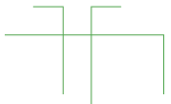
Unconnected lines
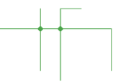
Connected lines
Labeling Pins and Parts
Parts can be given labels that can show names and values in both the schematic and PCB layout designs. To add a name label click on the name label and click on the desired part. A value label can be added to parts as well by clicking on the value label. Just a reminder, the value label is still just a name and does not have any relation to the part’s characteristics.

Name Icon
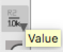
Value Icon
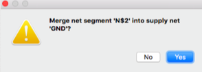
Pins can be named as well by giving them labels by clicking on the label icon and clicking on the desired pin.If a pin is named exactly with the same name to another pin, a window should pop up asking to connect the pins. If clicked true, the pins would be automatically connected without showing a line. The labels appearance can be changed by clicking on the tag icon and the size of the label can be changed as well.

Label Icon

Regular and Tag Icons
Changing Size Icon
EagleCAD Libraries
EagleCAD has a lot of different libraries from various retailers and manufacturers. It also has the regular parts such as supplies, passive components, .. etc. However, sometimes the desired part is not found in the EagleCAD built-in library so in that case a new library should be added.
Adding Libraries
To add a library, its “.lbr” file should be downloaded first from the manufacturers’ website or from different websites that provide eagle libraries:
Once the “.lbr” file is downloaded it should be placed in the “lbr” folder in the application’s folders. After that, the library should be indicated as used in the library manager window.
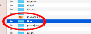
Placing library in lbr Folder
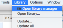
Library Manager
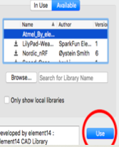
Using a Library
Testing
Verify Connected Pins
If the pins were labeled with similar names, their connection can be checked by clicking the show icon. Once the show icon is clicked, by clicking on any pin it would show the connected pins the clicked pin in bold font. It is very helpful to trace pins and check if all the parts are connected correctly.

Show Icon

Connected Pins
Checking Errors
After creating the schematic, the design should be checked if it has any errors. By clicking on the ERC icon a window should pop up showing any electrical errors. Make sure that you have no errors befor going to the PCD layout part of designing.
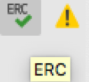
ERC Icon
Training Material
Schematic Training
Further trainings on creating EagleCAD schematics can be found here:
PCB Layout Training
Training on the making of the layout version of the custom PCB can be found in this blog written by Charles Banuelos (MFG DM).